Raspberry Pi computer hardware
Introduction
Edit this on GitHub
Raspberry Pi makes computers in several different series:
-
Single-board computers (SBCs). The flagship Raspberry Pi series offers high-performance hardware, a full Linux operating system, and a variety of common ports in a form factor roughly the size of a credit card.
-
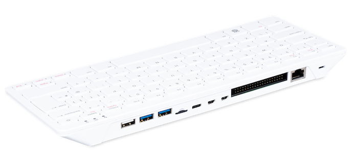
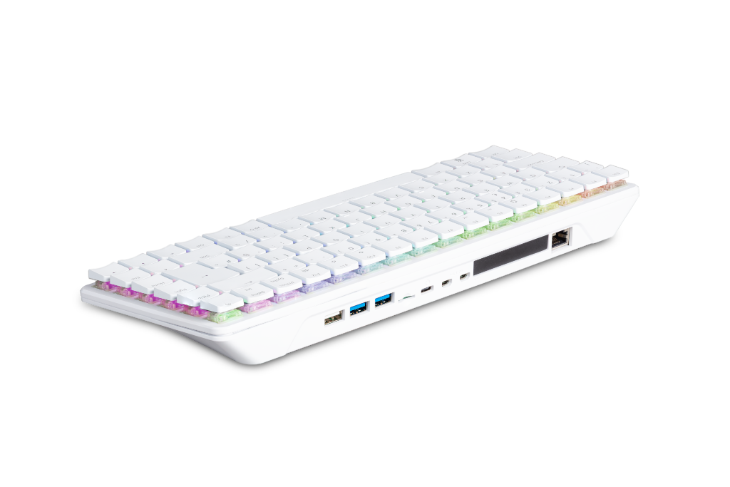
Keyboard computers (X00). Raspberry Pi keyboard computers combine SBC hardware, a full Linux operating system, and common ports inside a compact keyboard case.
-
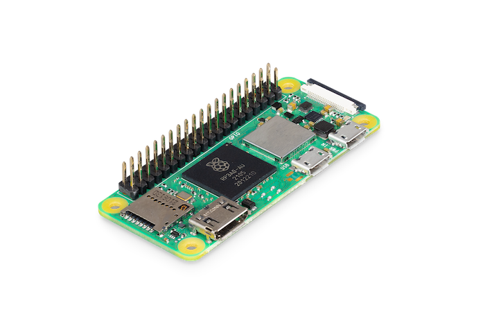
Zero. Small and affordable models in a minimal form factor that provide a full Linux operating system and essential ports with low power consumption.
-
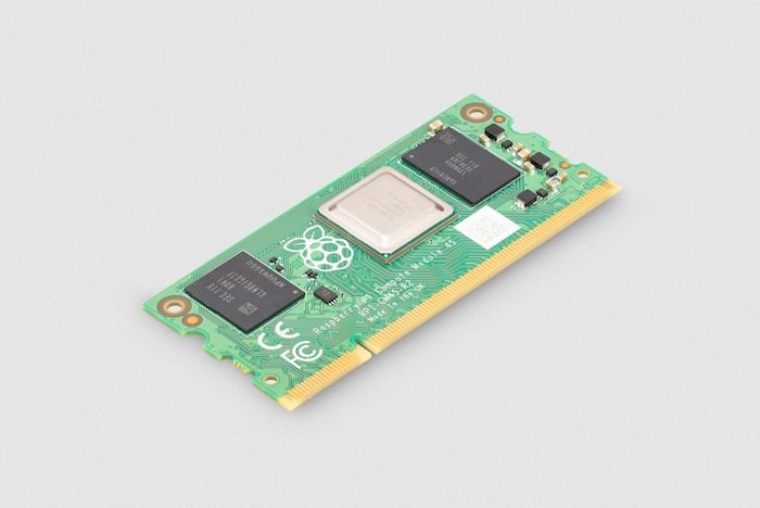
Compute Module (CM). Boards designed for embedded and industrial applications that provide the same hardware as flagship SBCs but in a smaller form factor with no on-board connectors. Instead, they connect to a separate baseboard that supplies the necessary ports and pins.
-
Pico (microcontroller boards). Small and versatile microcontroller boards that don’t run Linux. Instead of removable storage, programs are flashed directly onto on-board memory. Pico microcontrollers are ideal for real-time control and lightweight embedded projects.
Flagship single-board computer (SBC) series
Model B indicates the presence of an Ethernet port. Model A indicates a lower-cost model in a smaller form factor with no Ethernet port, reduced RAM, and fewer USB ports to limit board height.
|
Important
|
Raspberry Pi 2 Model B revisions 1.1 and 1.2 have reached End-of-Life (EoL) due to the discontinuation of the core SoC used in these products. The official EoL date was 16 October 2025. Raspberry Pi 2 Model B revision 1.3 offers the same mechanical footprint and a BCM2837B0 processor, and so is recommended for existing designs. For more information, see the official Obsolescence Notice. |
| Model | SoC | Memory | GPIO | Connectivity |
|---|---|---|---|---|

Raspberry Pi Model B
|
256 MB 512 MB |
26-pin GPIO header |
|
|

Raspberry Pi Model A
|
256 MB |
26-pin GPIO header |
|
|

Raspberry Pi Model B+
|
512 MB |
40-pin GPIO header |
|
|

Raspberry Pi Model A+
|
256 MB 512 MB |
40-pin GPIO header |
|
|

Raspberry Pi 2 Model B
|
1 GB |
40-pin GPIO header |
|
|

Raspberry Pi 3 Model B
|
1 GB |
40-pin GPIO header |
|
|

Raspberry Pi 3 Model B+
|
1 GB |
40-pin GPIO header |
|
|

Raspberry Pi 3 Model A+
|
512 MB |
40-pin GPIO header |
|
|

Raspberry Pi 4 Model B
|
1 GB 2 GB 3 GB 4 GB 8 GB |
40-pin GPIO header |
|
|

Raspberry Pi 5
|
1 GB 2 GB 4 GB 8 GB 16 GB |
40-pin GPIO header |
|
For more information about the ports on the Raspberry Pi flagship series, see the Schematics and mechanical drawings.
Keyboard computer (X00) series
Keyboard series devices use model identifiers of the form <X00>, where X indicates the corresponding flagship single-board computer (SBC) series device. For example, Raspberry Pi 400 is the keyboard version of Raspberry Pi 4. For more detailed information about Raspberry Pi keyboard computers, see Keyboard computers.
| Model | SoC | Memory | GPIO | Connectivity |
|---|---|---|---|---|

Raspberry Pi 400
|
4 GB |
40-pin GPIO header |
|
|
Raspberry Pi 500
|
8 GB |
40-pin GPIO header |
|
|
Raspberry Pi 500+
|
16 GB |
40-pin GPIO header |
|
Zero series
The first generation of Raspberry Pi Zero that include the H suffix have header pins pre-soldered to the GPIO header. Raspberry Pi Zero 2 specifies with headers instead of using the H suffix. Models that lack the H or with headers suffix don’t come with header pins attached to the GPIO header; the user must solder pins manually or attach a third-party pin kit.
Raspberry Pi Zero boards that include the W suffix come with wireless connectivity. Aside from wireless, all Zero models have the following connectivity:
-
A microSD card slot
-
A mini HDMI port
-
2 × micro-USB ports (one for input power, one for external devices)
Since version 1.3 of the original Zero, all Zero models also include a mini 22-pin, 0.5 mm (fine) pitch, 11.5 mm width, CSI (camera) port.
| Model | SoC | Memory | GPIO | Wireless Connectivity |
|---|---|---|---|---|

Raspberry Pi Zero
|
512 MB |
40-pin GPIO header (unpopulated) |
none |
|

Raspberry Pi Zero W
|
512 MB |
40-pin GPIO header (unpopulated) |
|
|

Raspberry Pi Zero WH
|
512 MB |
40-pin GPIO header |
|
|

Raspberry Pi Zero 2 W
|
512 MB |
40-pin GPIO header (unpopulated) |
|
|
Raspberry Pi Zero 2 W with headers
|
512 MB |
40-pin GPIO header |
|
Compute Module series
|
Important
|
Raspberry Pi Compute Module 3 (CM3) and Compute Module 3 Lite (CM3Lite) have reached End-of-Life (EoL) due to the discontinuation of the core SoC used in these products. The official EoL date was 16 October 2025. The closest equivalent to CM3 is Raspberry Pi Compute Module 3+, which offers the same mechanical footprint, improved thermal design, and a BCM2837B0 processor, and so is recommended for existing designs. For new designs requiring the SODIMM form factor, we recommend Compute Module 4S. For all other new designs, we recommend Compute Module 4 or Compute Module 5. For more information, see the official Obsolescence Notice. |
For more detailed information about the Raspberry Pi Compute Module hardware, see Compute Module hardware.
| Model | SoC | Memory | Storage | Form factor | Wireless Connectivity |
|---|---|---|---|---|---|

Raspberry Pi Compute Module 1
|
512 MB |
4 GB |
DDR2 SODIMM |
none |
|

Raspberry Pi Compute Module 3
|
1 GB |
0 GB (Lite) 4 GB |
DDR2 SODIMM |
none |
|

Raspberry Pi Compute Module 3+
|
1 GB |
0 GB (Lite) 8 GB 16 GB 32 GB |
DDR2 SODIMM |
none |
|
Raspberry Pi Compute Module 4S
|
1 GB 2 GB 4 GB 8 GB |
0 GB (Lite) 8 GB 16 GB 32 GB |
DDR2 SODIMM |
none |
|
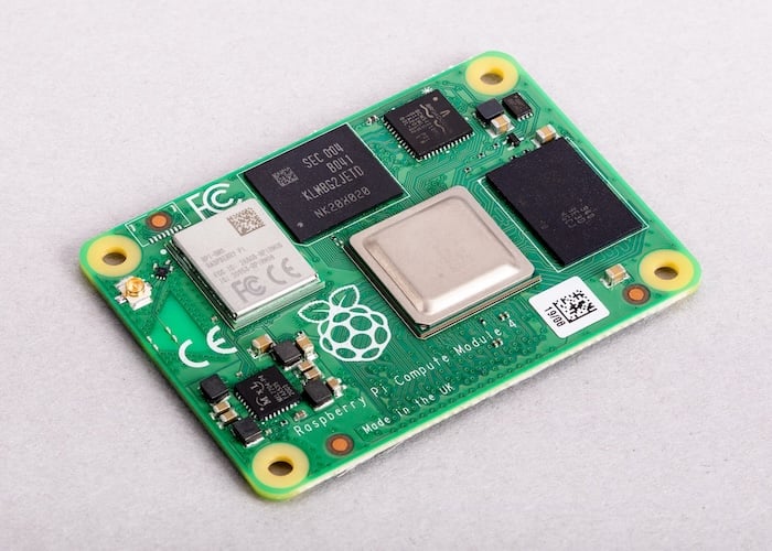
Raspberry Pi Compute Module 4
|
1 GB 2 GB 4 GB 8 GB |
0 GB (Lite) 8 GB 16 GB 32 GB |
dual 100-pin high density connectors |
optional:
|
|
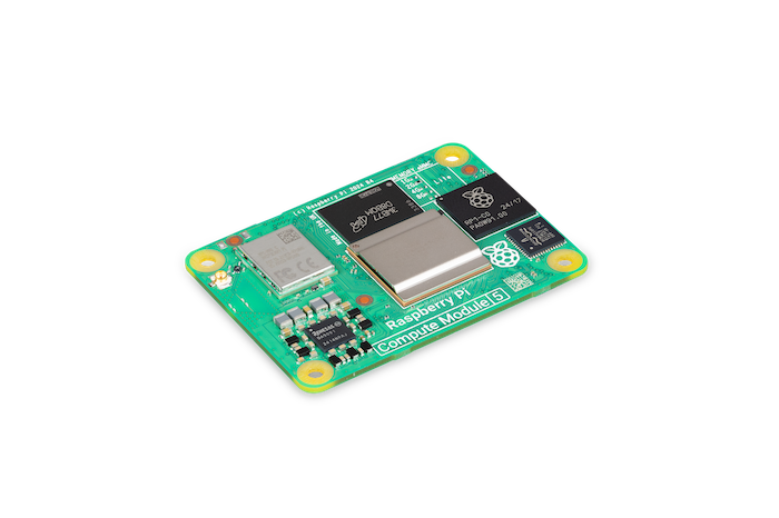
Raspberry Pi Compute Module 5
|
2 GB 4 GB 8 GB 16 GB |
0 GB (Lite) 16 GB 32 GB 64 GB |
dual 100-pin high density connectors |
optional:
|
|
Note
|
Compute Modules that use the physical DDR2 SODIMM form factor are not compatible with DDR2 SODIMM electrical specifications. |
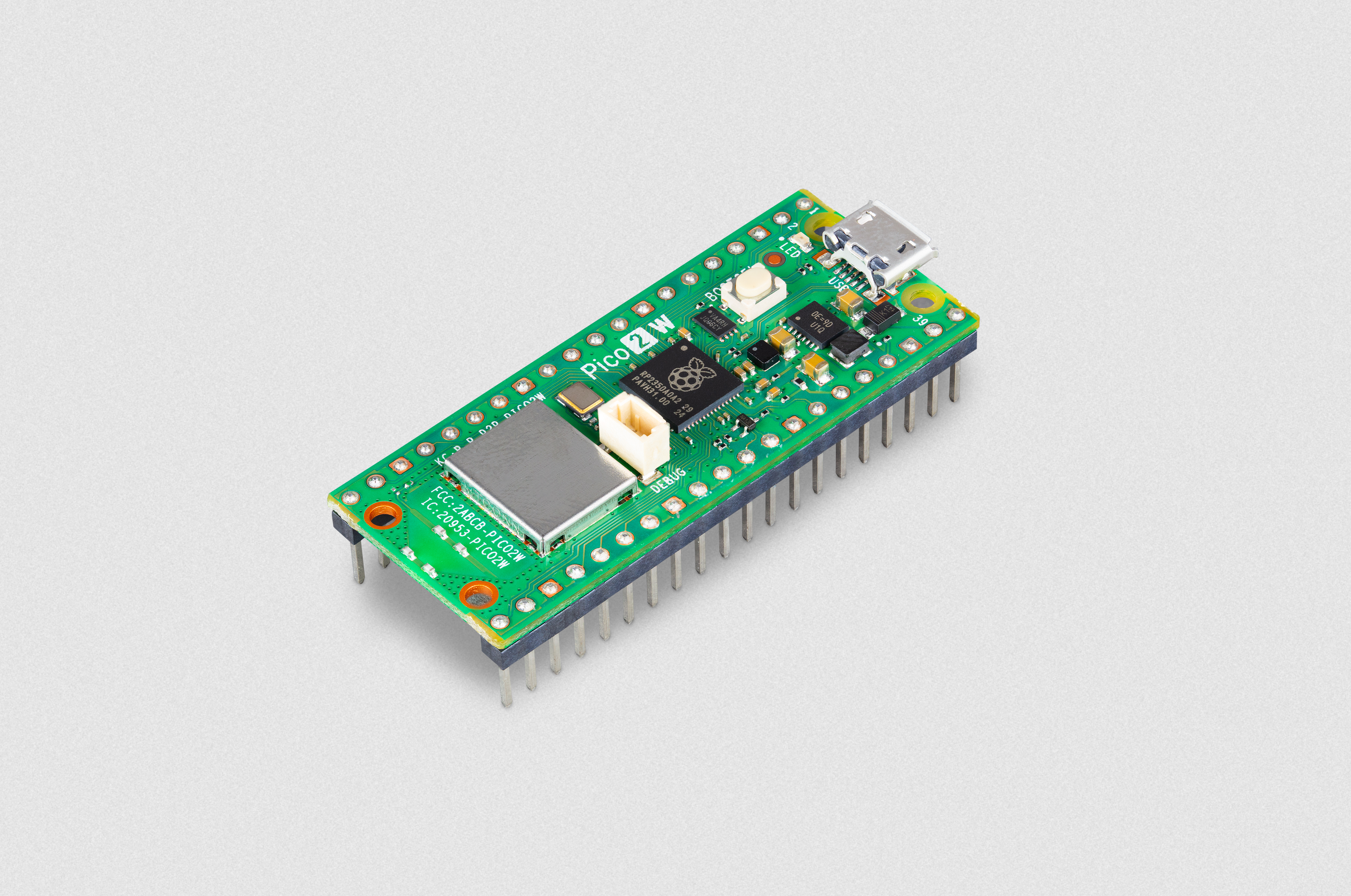
Pico microcontroller boards
The first generation of Raspberry Pi Pico that include the H suffix have header pins pre-soldered to the GPIO header. Raspberry Pi Pico 2 specifies with headers instead of using the H suffix. Models that lack the H or with headers suffix don’t come with header pins attached to the GPIO header; the user must solder pins manually or attach a third-party pin kit.
Raspberry Pi Pico boards that include the W suffix come with wireless connectivity.
| Model | SoC | Memory | Storage | GPIO | Wireless Connectivity |
|---|---|---|---|---|---|

Raspberry Pi Pico
|
264 kB |
2 MB |
two 20-pin GPIO headers (unpopulated) |
none |
|

Raspberry Pi Pico H
|
264 kB |
2 MB |
two 20-pin GPIO headers |
none |
|
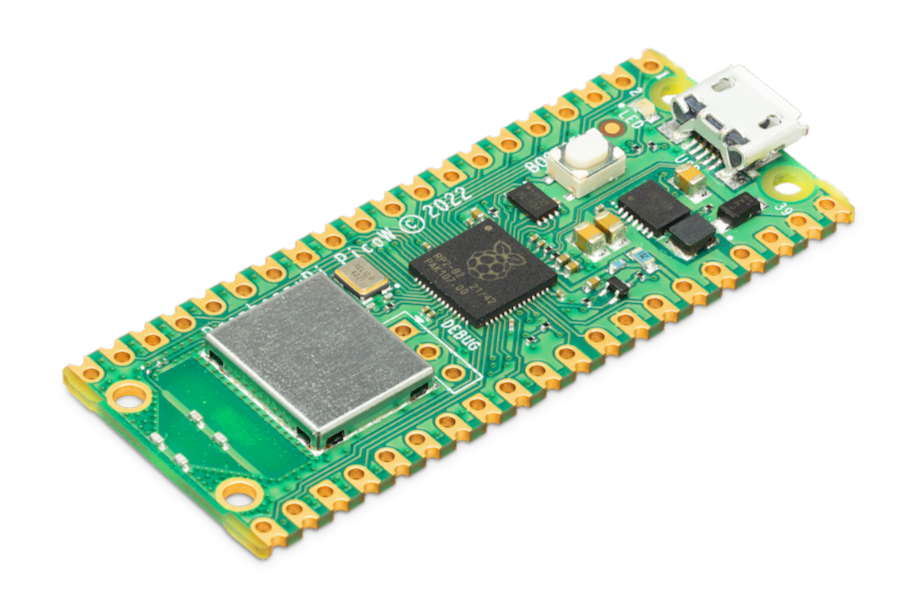
Raspberry Pi Pico W
|
264 kB |
2 MB |
two 20-pin GPIO headers (unpopulated) |
|
|

Raspberry Pi Pico WH
|
264 kB |
2 MB |
two 20-pin GPIO headers |
|
|

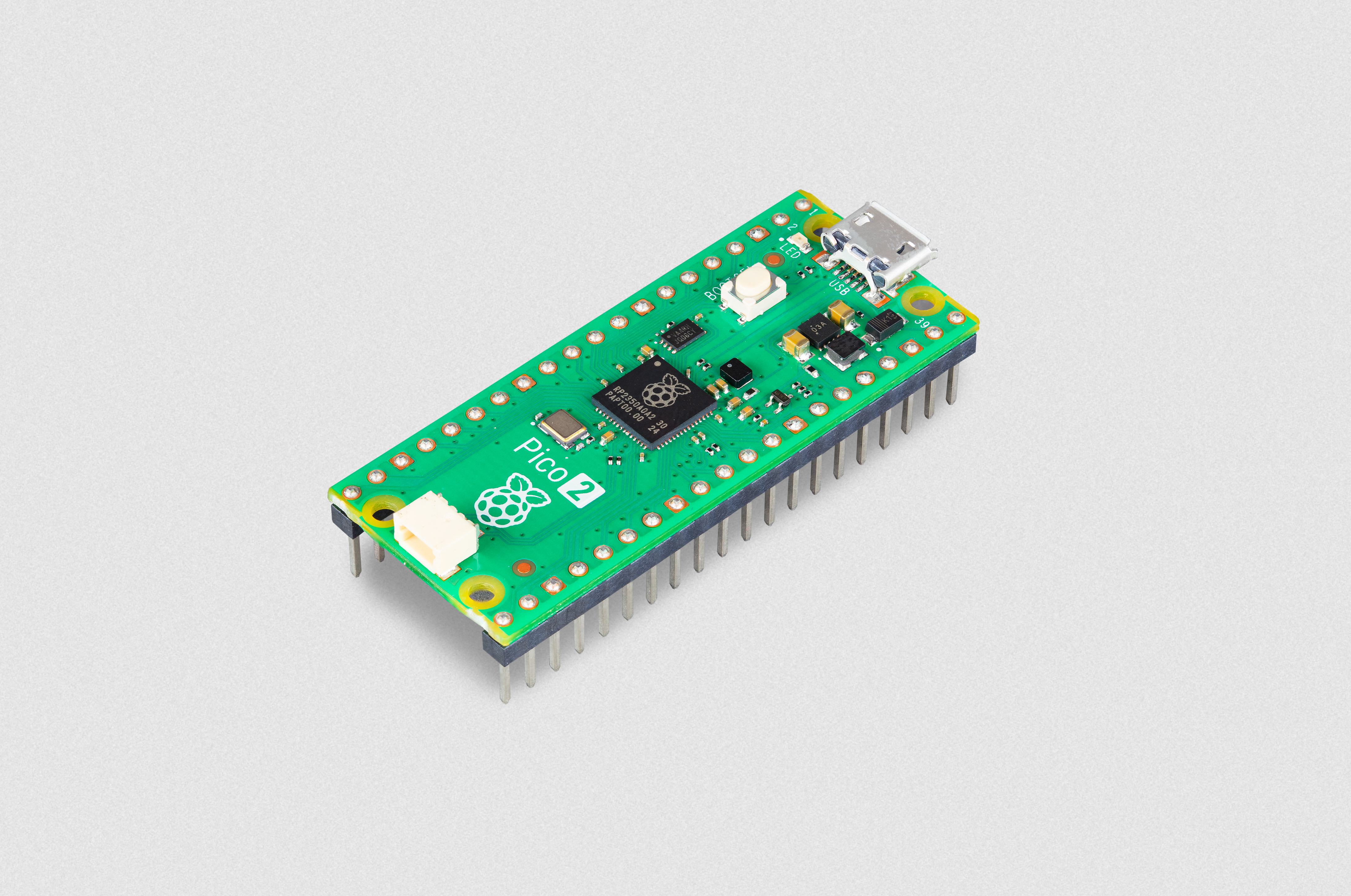
Raspberry Pi Pico 2
|
520 kB |
4 MB |
two 20-pin GPIO headers (unpopulated) |
none |
|

Raspberry Pi Pico 2 W
|
520 kB |
4 MB |
two 20-pin GPIO headers (unpopulated) |
|
|
Raspberry Pi Pico 2 with headers
|
520 kB |
4 MB |
two 20-pin GPIO headers (unpopulated) |
none |
|
Raspberry Pi Pico 2 W with headers
|
520 kB |
4 MB |
two 20-pin GPIO headers (unpopulated) |
|
For more information about Raspberry Pi Pico models, see the Pico documentation.
Schematics and mechanical drawings
Edit this on GitHub
Schematics for the various Raspberry Pi board versions:
Raspberry Pi 1 Model A+
|
Note
|
Mechanical drawings for the Raspberry Pi 3 Model A+ are also applicable to the Raspberry Pi 1 Model A+. |
Raspberry Pi Zero 2 W
Test pad locations
The Raspberry Pi Zero 2 W has a number of test pad locations used during production of the board.

| Label | Function | X (mm from origin) | Y (mm from origin) |
|---|---|---|---|
STATUS_LED |
Power state of LED (LOW = ON) |
5.15 |
8.8 |
CORE |
Processor power |
6.3 |
18.98 |
RUN |
Connect to GND to reset |
8.37 |
22.69 |
5V |
5V input |
8.75 |
11.05 |
5V |
5V input |
11.21 |
6.3 |
GND |
Ground pin |
10.9 |
3.69 |
GND |
Ground pin |
17.29 |
2.41 |
USB_DP |
USB port |
22.55 |
1.92 |
USB_DM |
USB port |
24.68 |
1.92 |
OTG |
On-the-go ID pin |
39.9 |
7.42 |
1V8 |
1.8V analog supply |
42.03 |
8.42 |
TV |
Composite TV out |
45.58 |
3.17 |
GND |
Ground pin |
49.38 |
3.05 |
GND |
Ground pin |
55.99 |
22.87 |
3V3 |
3.3V I/O supply |
48.55 |
22.44 |
SD_CLK |
SD Card clock pin |
60.95 |
18.45 |
SD_CMD |
SD Card command pin |
58.2 |
16.42 |
SD_DAT0 |
SD data pin |
58.13 |
20.42 |
SD_DAT1 |
SD data pin |
60.65 |
21.1 |
SD_DAT2 |
SD data pin |
57.78 |
13.57 |
SD_DAT3 |
SD data pin |
60.8 |
15.22 |
BT_ON |
Bluetooth power status |
25.13 |
19.55 |
WL_ON |
Wireless LAN power status |
27.7 |
19.2 |
Product compliance and safety
Edit this on GitHub
All Raspberry Pi products have undergone extensive compliance testing. For more information see the Product Information Portal.
Flammability rating
The PCBs used in Raspberry Pi devices adhere to UL94-V0.
|
Note
|
This applies to the PCBs only. |
Raspberry Pi Compliance Support
The Compliance Support programme is designed to eliminate the burden of navigating compliance issues and make it easier for companies to bring new products to consumers. It provides access to the same test engineers who worked on our Raspberry Pis during their compliance testing, connecting the user to a dedicated team at UL who assess and test the user’s product, facilitated by their in-depth knowledge of Raspberry Pi.
Find out more about the Raspberry Pi Compliance Support Programme.
Powered by Raspberry Pi
The Powered by Raspberry Pi program provides a process for companies wanting to use a form of the Raspberry Pi logo, and covers products with Raspberry Pi computers or silicon inside, and services provided by a Raspberry Pi. If you wish to start the process to apply you can do so online.
Approved Design Partners
Our list of Approved Design Partners provides a set of consultancies which we work closely with and support so they can provide paid-for design services across hardware, software, and mechanical fields.
Frequency management and thermal control
Edit this on GitHub
All Raspberry Pi models perform a degree of thermal management to avoid overheating under heavy load. The SoCs have an internal temperature sensor, which software on the GPU polls to ensure that temperatures do not exceed a limit which we define as 85°C on all models. It is possible to set this to a lower value, but not to a higher one. As the device approaches the limit, various frequencies and sometimes voltages used on the chip (Arm, GPU) are reduced. This reduces the amount of heat generated, keeping the temperature under control.
When the core temperature is between 80°C and 85°C, the Arm cores will be progressively throttled back. If the temperature reaches 85°C, both the Arm cores and the GPU will be throttled back.
For Raspberry Pi 3 Model B+, the PCB technology has been changed to provide better heat dissipation and increased thermal mass. In addition, a soft temperature limit has been introduced, with the goal of maximising the time for which a device can "sprint" before reaching the hard limit at 85°C. When the soft limit is reached, the clock speed is reduced from 1.4 GHz to 1.2 GHz, and the operating voltage is reduced slightly. This reduces the rate of temperature increase: we trade a short period at 1.4 GHz for a longer period at 1.2 GHz. By default, the soft limit is 60°C, and this can be changed via the temp_soft_limit setting in config.txt.
The Raspberry Pi 4 Model B continues with the same PCB technology as the Raspberry Pi 3 Model B+, to help dissipate excess heat. There is currently no soft limit defined.
Use DVFS
|
Note
|
Discussion of DVFS applies to 4-series devices only (Raspberry Pi 4B, Compute Module 4, Compute Module 4S, and Raspberry Pi 400). |
Raspberry Pi 4 devices implement dynamic voltage and frequency scaling (DVFS). This technique allows 4-series devices to run at lower temperatures whilst still providing the same performance.
Various clocks (for example, Arm, Core, V3D, ISP, H264, HEVC) inside the SoC are monitored by the firmware, and whenever they are not running at full speed, the voltage supplied to the particular part of the chip driven by the clock is reduced relative to the reduction from full speed. In effect, only enough voltage is supplied to keep the block running correctly at the specific speed at which it is running. This can result in significant reductions in power used by the SoC, and therefore in the overall heat being produced.
Due to possible system stability problems involved with running an undervoltage, especially when using undervoltaged fixed clock peripherals (eg. PCIe), three DVFS modes are available and can be configured in /boot/firmware/config.txt with the below properties. Most systems should use dvfs=3, headless systems may benefit from a small power reduction with dvfs=1 at the risk of PCIe stability issues.
| property=value | Description |
|---|---|
|
allow undervoltage |
|
fixed voltage for default operating frequencies |
|
scale voltage up on demand for over clocking (default). If |
|
Note
|
This setting has been removed on 5-series devices and is effectively always mode 3. |
In addition, a more stepped CPU governor is also used to produce finer-grained control of Arm core frequencies, which means the DVFS is more effective. The steps are now 1500 MHz, 1000 MHz, 750 MHz, and 600 MHz. These steps can also help when the SoC is being throttled, and mean that throttling all the way back to 600 MHz is much less likely, giving an overall increase in fully loaded performance.
The default CPU governor is ondemand. The governor can be manually changed with the cpufreq-set command (from the cpufrequtils package) to reduce idle power consumption:
$ sudo apt install cpufrequtils
$ sudo cpufreq-set -g powersave
Measure temperatures
Due to the architecture of the SoCs used on Raspberry Pi devices, and the use of the upstream temperature monitoring code in the Raspberry Pi OS distribution, Linux-based temperature measurements can be inaccurate. However, the vcgencmd command provides an accurate and instantaneous reading of the current SoC temperature, as it communicates with the GPU directly:
$ vcgencmd measure_tempAdd heat sinks
Thanks to built-in throttling, heatsinks are not necessary to prevent overheating damage to the SoC. However, a heatsink or small fan can reduce thermal throttling and improve performance. Mount the Raspberry Pi vertically for the best airflow and thus slightly improved heat dissipation.
Fan cases
To ensure the best performance for your Raspberry Pi, use an active cooling solution such as a fan. Raspberry Pi firmware manages fan speeds for all official fans.
Raspberry Pi 4 fan
For Raspberry Pi 4, add the Raspberry Pi 4 Case Fan to the lid of the Raspberry Pi 4 case.
Raspberry Pi 5 fans
For Raspberry Pi 5, use one of the official fan options:
Both of the Raspberry Pi 5 fan options plug into the four-pin JST-SH PWM fan connector located in the upper right of the board between the 40-pin GPIO header and the USB 2.0 ports. The fan connector pulls from the same current limit as USB peripherals. We recommend the Active Cooler case for overclockers, since it provides better cooling performance.
As the temperature of the Raspberry Pi 5 increases, the fan reacts in the following way:
-
below 50°C, the fan does not spin at all (0% speed)
-
at 50°C, the fan turns on at a low speed (30% speed)
-
at 60°C, the fan speed increases to a medium speed (50% speed)
-
at 67.5°C, the fan speed increases to a high speed (70% speed)
-
at 75°C the fan increases to full speed (100% speed)
Temperature decreases use the same mapping with a 5°C hysteresis; fan speed decreases when the temperature drops to 5°C below each of the above thresholds.
|
Note
|
The temperature, hysteresis and speed figures given above can be adjusted by using the various fan_tempN, fan_tempN_hyst and fan_tempN_speed dtoverlay settings (where N is 0, 1, 2 or 3). See the overlays README for full details. For example, adding dtparam=fan_temp0=55000 to /boot/firmware/config.txt will cause the fan to remain off until the Raspberry Pi 5’s temperature reaches 55°C.
|
At boot the fan is turned on, and the tachometer input is checked to see if the fan is spinning. If it is, then the cooling_fan device tree overlay is enabled. This overlay is in bcm2712-rpi-5-b.dtb by default, but with status=disabled.
Raspberry Pi boot EEPROM
Edit this on GitHub
The following Raspberry Pi models use an EEPROM to boot the system:
-
Flagship models since Raspberry Pi 4B
-
Compute Module models since CM4 (including CM4S)
-
Keyboard models since Raspberry Pi 400
All other models of Raspberry Pi computer use the bootcode.bin file located in the boot filesystem.
|
Note
|
You can find the scripts and pre-compiled binaries used to create rpi-eeprom in the rpi-eeprom GitHub repository.
|
Reset the Raspberry Pi bootloader
This section provides instructions for reflashing the bootloader to reset it. You typically do this to recover a system that fails to boot, or to reset the bootloader configuration.
If, instead of resetting the bootloader, you want to upgrade the bootloader version or choose a different boot order, see Update the bootloader in the Configuration page.
The following instructions are relevant only to newer Raspberry Pi models that store the bootloader in an on-board SPI flash EEPROM:
-
Flagship single-board computers (SBCs) since Raspberry Pi 4B.
-
Compute Modules since CM4 (including CM4S).
-
All keyboard computers (Raspberry Pi 400, 500, and 500+).
On other Raspberry Pi models the boot ROM always loads the bootcode.bin file located in the boot partition of your boot media.
Diagnose bootloader issues
If your Raspberry Pi device fails to boot, the bootloader provides feedback in the following ways:
-
LED activity. The green LED on your Raspberry Pi can flash in specific patterns to indicate specific errors. Check the LED warning flash codes to identify errors based on the flash pattern. For example, seven short flashes of the green LED means that the kernel image wasn’t found.
-
HDMI diagnostic screen. On newer devices, the bootloader can display a diagnostic screen over HDMI during startup. If you have a monitor connected to your Raspberry Pi, this screen provides information like the bootloader version and build date, the detected boot order, and specific error codes if the OS fails to load. For more information, see Boot diagnostics.
Reflash the bootloader
Reflash the bootloader if your system fails to boot or if you want to reset the bootloader configuration. Reflashing the bootloader clears any local bootloader configuration that might be preventing your Raspberry Pi from booting.
|
Note
|
You can also reflash the bootloader using USB rpiboot. This method is typically used to mass provision Compute Modules. Reflashing the bootloader over USB is also the only option available for CM4 and CM4S. For more information, see Compute Module hardware.
|
To reflash the bootloader on your Raspberry Pi device:
-
Connect a spare or empty microSD storage device to your host computer.
-
Find and open Imager on your host computer.
-
In the Device tab, select your Raspberry Pi model from the list, and then select Next.
-
In the OS tab, scroll down to the bottom of the list and select Misc utility images > Bootloader > SD Card Boot, then select Next.
-
In the Storage tab, select your storage device and then select Next.
-
In the Writing tab, select Write.
-
Select I understand, erase and write; wait for the write to complete and then select Finish.
-
Eject the storage device from your host computer and then plug it into your Raspberry Pi.
-
Boot your Raspberry Pi by plugging it into power.
-
When the green activity LED flashes with a steady pattern and after your HDMI display shows a green screen, turn off your Raspberry Pi by disconnecting it from power and eject the boot media.
Update the bootloader configuration
The default version of the bootloader represents the latest factory default firmware image. It updates to provide critical bug fixes, hardware support and periodically after features have been tested in the latest release.
The latest bootloader updates more often to include the latest fixes and improvements.
Advanced users can switch to the latest bootloader to get the latest functionality.
First, ensure that your Raspberry Pi runs the latest software. Run the following command to update:
$ sudo apt update && sudo apt full-upgradeNext, run the following command to open raspi-config:
$ sudo raspi-configNavigate to Advanced Options > Bootloader Version. Select Latest, then choose Yes to confirm. Select Finish and confirm that you want to reboot.
If you run sudo rpi-eeprom-update, you should see that a more recent version of the bootloader is available and it’s the latest release.
*** UPDATE AVAILABLE ***
BOOTLOADER: update available
   CURRENT: Thu 18 Jan 13:59:23 UTC 2024 (1705586363)
    LATEST: Mon 22 Jan 10:41:21 UTC 2024 (1705920081)
   RELEASE: latest (/lib/firmware/raspberrypi/bootloader-2711/latest)
            Use raspi-config to change the release.

  VL805_FW: Using bootloader EEPROM
     VL805: up to date
   CURRENT: 000138c0
    LATEST: 000138c0
Now you can update your bootloader.
$ sudo rpi-eeprom-update -a
$ sudo reboot
Reboot, then run sudo rpi-eeprom-update. You should now see that the CURRENT date has updated to the latest version of the bootloader:
BOOTLOADER: up to date
   CURRENT: Mon 22 Jan 10:41:21 UTC 2024 (1705920081)
    LATEST: Mon 22 Jan 10:41:21 UTC 2024 (1705920081)
   RELEASE: latest (/lib/firmware/raspberrypi/bootloader-2711/latest)
            Use raspi-config to change the release.

  VL805_FW: Using bootloader EEPROM
     VL805: up to date
   CURRENT: 000138c0
    LATEST: 000138c0
Read the current bootloader configuration
To view the configuration used by the current running bootloader, run the following command:
$ rpi-eeprom-configRead the configuration from an bootloader image
To read the configuration from a bootloader image:
$ rpi-eeprom-config pieeprom.binEditing the current bootloader configuration
The following command loads the current bootloader configuration into a text editor. When the editor is closed, rpi-eeprom-config applies the updated configuration to latest available bootloader release and uses rpi-eeprom-update to schedule an update when the system is rebooted:
$ sudo -E rpi-eeprom-config --edit
$ sudo reboot
If the updated configuration is identical or empty, then no changes are made.
The editor is selected by the EDITOR environment variable.
Automatic updates
The rpi-eeprom-update systemd service runs at startup and applies an update if a new image is available, automatically migrating the current bootloader configuration.
To disable automatic updates:
$ sudo systemctl mask rpi-eeprom-updateTo re-enable automatic updates:
$ sudo systemctl unmask rpi-eeprom-update|
Note
|
If the FREEZE_VERSION bootloader config is set then the update service will skip any automatic updates. This removes the need to individually disable the update service if there are multiple operating systems installed, or when swapping SD cards. |
rpi-eeprom-update
Raspberry Pi OS uses the rpi-eeprom-update script to implement an automatic update service. The script can also be run interactively or wrapped to create a custom bootloader update service.
Reading the current bootloader version:
$ vcgencmd bootloader_versionCheck if an update is available:
$ sudo rpi-eeprom-updateInstall the update:
$ sudo rpi-eeprom-update -a
$ sudo reboot
Cancel the pending update:
$ sudo rpi-eeprom-update -rInstalling a specific bootloader image:
$ sudo rpi-eeprom-update -d -f pieeprom.binThe -d flag instructs rpi-eeprom-update to use the configuration in the specified image file instead of automatically migrating the current configuration.
Display the built-in documentation:
$ rpi-eeprom-update -hA/B bootloader updates
A/B EEPROM bootloader updates protect against a Raspberry Pi device being unable to boot after an interrupted update — this protects the device if power is removed from it mid-update.
A/B-capable firmware splits the EEPROM into two partitions, A and B. At any time, one partition is 'committed' and is the partition that the device boots from by default. Updates are written to the other partition, leaving the committed partition untouched until the new image has been written in full and checked.
It is compatible only with the Raspberry Pi 5, Raspberry Pi Compute Module 5, and Raspberry Pi 5 keyboard computer devices.
A/B-capable firmware also supports a tryboot rollback mechanism that can test a new partition before committing to it. For more information, see the rpi-eeprom-ab README.
For information about A/B update for Raspberry Pi OS, see A/B boot update.
Enable A/B bootloader updates
|
Note
|
While A/B firmware updates are enabled, tools that write to EEPROM directly (such as flashrom) no longer work.
|
To enable or disable A/B firmware updates with raspi-config:
-
From the command line, run the following command to update your Raspberry Pi software to the latest version:
$ sudo apt update && sudo apt full-upgrade -
From the command line, run the following command to open
raspi-config:$ sudo raspi-config -
Navigate to
6 Advanced Options > A14 AB Firmwareand selectEnableorDisable. -
Select
Finishand reboot when prompted. -
From the command line, run the following command to perform the A/B update.
$ rpi-eeprom-update
Bootloader release status
The firmware release status corresponds to a particular subdirectory of bootloader firmware images (/lib/firmware/raspberrypi/bootloader/...), and can be changed to select a different release stream.
-
default– Updated for new hardware support, critical bug fixes and periodic update for new features that have been tested via thelatestrelease -
latest– Updated when new features are available
Since the release status string is just a subdirectory name, it’s possible to create your own release streams, for example, a pinned release or custom network boot configuration.
Changing the bootloader release
|
Note
|
You can change which release stream is to be used during an update by editing the /etc/default/rpi-eeprom-update file and changing the FIRMWARE_RELEASE_STATUS entry to the appropriate stream.
|
Updating the bootloader configuration in an bootloader image file
The following command replaces the bootloader configuration in pieeprom.bin with boot.conf and writes the new image to new.bin:
$ rpi-eeprom-config --config boot.conf --out new.bin pieeprom.bin
recovery.bin
At power on, the ROM found on BCM2711 and BCM2712 looks for a file called recovery.bin in the root directory of the boot partition on the SD card. If a valid recovery.bin is found then the ROM executes this instead of the contents of the EEPROM. This mechanism ensures that the bootloader flash image can always be reset to a valid image with factory default settings.
For more information, see EEPROM bootflow.
Bootloader update files
| Filename | Purpose |
|---|---|
|
Bootloader recovery executable |
|
Bootloader EEPROM image |
|
Bootloader EEPROM image – same as |
|
The sha256 checksum (and optional timestamp) of bootloader image ( |
|
The VLI805 USB firmware EEPROM image – Raspberry Pi 4B revision 1.3 and earlier only. |
|
The sha256 checksum of vl805.bin |
-
If the bootloader update image is called
pieeprom.upd, thenrecovery.binis renamed torecovery.000after the update has completed, then the system is rebooted. Becauserecovery.binis no longer present the ROM loads the newly updated bootloader from SPI flash and the OS is booted as normal. -
If the bootloader update image is called
pieeprom.binthenrecovery.binwill stop after the update has completed. On success the HDMI output will be green and the green activity LED is flashed rapidly. If the update fails, the HDMI output will be red and an error code will be displayed via the activity LED. -
The
.sigfiles contain the hexadecimal sha256 checksum of the corresponding image file on the first line, optionally followed by the timestamp of the image (ts: unixtime) on the next line; additional fields may be added in the future. -
The ROM found on BCM2711 and BCM2712 does not support loading
recovery.binfrom USB mass storage or TFTP. Instead, newer versions of the bootloader support a self-update mechanism where the bootloader is able to reflash the SPI flash itself. SeeENABLE_SELF_UPDATEon the bootloader configuration page. -
The temporary EEPROM update files are automatically deleted by the
rpi-eeprom-updateservice at startup.
For more information about the rpi-eeprom-update configuration file see rpi-eeprom-update -h.
EEPROM write protect
Both the bootloader and VLI EEPROMs support hardware write protection. See the eeprom_write_protect option for more information about how to enable this when flashing the EEPROMs.
Boot diagnostics
Edit this on GitHub
The bootloader on Raspberry Pi 4 or later flagship models can display diagnostic information at boot time on an HDMI display. To see this diagnostic information, power down the Raspberry Pi, disconnect the boot media (typically an SD card or SSD), then power back up. If your Raspberry Pi is connected to a display, you should see diagnostics similar to the following:

This diagnostics page will also appear if the bootloader is unable to boot from any boot media or network boot. This can happen if there is no bootable image on the boot media, if the boot media is defective, or if network boot parameters are incorrect.
To reboot while displaying the diagnostics page, power cycle the device. You can disconnect, then reconnect the power supply, or press and hold the power button, if your device has one.
The top line describes the model of Raspberry Pi and its memory capacity. The QR code is a link to the downloads page.
The diagnostic information is as follows:
| Line | Information |
|---|---|
|
Bootloader git version - RO (if EEPROM is write protected) - software build date |
|
the timestamp corresponding to when the EEPROM configuration was updated; this timestamp is checked in self-update mode to avoid updating to an old configuration |
|
If secure-boot is enabled, displays the processor revision (B0/C0) and signed-boot status flags; otherwise, this line is blank |
|
Board revision - serial number - Ethernet MAC address |
|
mode (current boot mode name and number) order (the BOOT ORDER configuration) retry (retry count in the current boot mode) restart (number of cycles through the list of boot modes) |
|
The SD card detect status (detected/not detected). |
|
Master Boot Record primary partitions type:LBA |
|
Filename for |
|
Network boot: link status (up/down), client IP address (ip), subnet (sn), default gateway (gw) |
|
Network boot: TFTP server IP address |
|
Indicates whether hotplug was detected ( |
To disable this diagnostics display, use the DISABLE_HDMI option in the bootloader configuration.
Raspberry Pi boot modes
Edit this on GitHub
The Raspberry Pi has a number of different stages of booting. This document explains how the boot modes work, and which ones are supported for Linux booting.
Special bootcode.bin-only boot mode
USB host and Ethernet boot can be performed by BCM2837-based Raspberry Pi devices – that is, Raspberry Pi 2B version 1.2, Raspberry Pi 3B, and Raspberry Pi 3B+ (Raspberry Pi 3A+ cannot net boot since it does not have a built-in Ethernet interface). In addition, all Raspberry Pi models prior to Raspberry Pi 4 can use a bootcode.bin-only method to enable USB host boot.
|
Note
|
Since Raspberry Pi 4, flagship devices do not use the bootcode.bin file. Instead, these devices use a bootloader located in an on-board EEPROM chip. For more information, see the documentation on EEPROM bootflow and SPI boot EEPROM.
|
Format an SD card as FAT32 and copy over the latest bootcode.bin. The SD card must be present in the Raspberry Pi for it to boot. After bootcode.bin is loaded from the SD card, the Raspberry Pi continues booting using USB host mode.
This is useful for the Raspberry Pi 1, 2, and Zero models, which are based on the BCM2835 and BCM2836 chips, and in situations where a Raspberry Pi 3 fails to boot (the latest bootcode.bin includes additional bugfixes for the Raspberry Pi 3B, compared to the boot code burned into the BCM2837A0).
If you have a problem with a mass storage device still not working, even with this bootcode.bin, then add a new file called "timeout" to the SD card. This will extend to six seconds the time for which it waits for the mass storage device to initialise.
bootcode.bin UART Enable
|
Note
|
For boards released prior to Raspberry Pi 4. |
For information on enabling UART with the EEPROM bootloader, see the bootloader configuration documentation.
It is possible to enable an early stage UART to debug booting issues (useful with the above bootcode.bin only boot mode). To do this, make sure you’ve got a recent version of the firmware (including bootcode.bin). To check if UART is supported in your current firmware:
$ strings bootcode.bin | grep BOOT_UARTTo enable UART from bootcode.bin:
$ sed -i -e "s/BOOT_UART=0/BOOT_UART=1/" bootcode.binNext, connect a suitable USB serial cable to your host computer (a Raspberry Pi will work, although you may find that the easiest path is to use a USB serial cable, since it’ll work out the box without any pesky config.txt settings). Use the standard pins 6, 8 and 10 (GND, GPIO14, GPIO15) on a Raspberry Pi or Compute Module.
Then use screen on Linux or macOS or putty on Windows to connect to the serial.
Set up your serial to receive at 115200-8-N-1, and then boot your Raspberry Pi. You should get an immediate serial output from the device as bootcode.bin runs.
USB boot modes
Edit this on GitHub
There are two separate boot modes for USB:
-
USB device boot
-
USB host boot
The firmware chooses between the two modes at boot time based on the OTP bits. Two bits control USB boot. The first enables USB device boot and is enabled by default; the second enables USB host boot.
If the USB host boot mode bit is set, the processor reads the OTGID pin to decide whether to boot as a host (driven to zero as on any Raspberry Pi Model B/B+) or as a device (left floating). The Raspberry Pi Zero has access to the OTGID pin through the USB connector; the Compute Module has access to the OTGID pin on the edge connector.
Some other OTP bits allow certain GPIO pins to select the boot modes.
USB device boot mode
|
Note
|
USB device boot is available on the Compute Module series, Zero series, and Model A variants of the flagship series. |
When this boot mode is activated (usually after a failure to boot from the SD card), the Raspberry Pi puts its USB port into device mode and awaits a USB reset from the host. Example code showing how the host needs to talk to the Raspberry Pi can be found on Github.
The host first sends a structure to the device down control endpoint 0. This contains the size and signature for the boot (security is not enabled, so no signature is required). Secondly, code is transmitted down endpoint 1 (bootcode.bin). Finally, the device will reply with one of the following codes:
-
0– Success -
0x80– Failure
USB host boot mode
|
Note
|
Host boot is available on the Compute Module series since Compute Module 3, Zero series since Zero 2 W, Raspberry Pi 2B (version 1.2), Raspberry Pi 3B, and all flagship series devices since Raspberry Pi 3B+. Raspberry Pi 3A+ supports mass storage boot, but not network boot. |
USB host boot mode uses the following logic:
-
Enable the USB port and wait for D+ line to be pulled high indicating a USB 2.0 device (we only support USB2.0)
-
If the device is a hub:
-
Enable power to all downstream ports of the hub
-
For each port, loop for a maximum of two seconds (or five seconds if
program_usb_boot_timeout=1has been set)-
Release from reset and wait for D+ to be driven high to indicate that a device is connected
-
If a device is detected:
-
Send "Get Device Descriptor"
-
If
VID == SMSC&&PID == 9500-
Add device to Ethernet device list
-
-
-
If the class interface is mass storage class
-
Add device to mass storage device list
-
-
-
-
-
Else
-
Enumerate single device
-
-
Go through mass storage device list
-
Boot from mass storage device
-
-
Go through Ethernet device list
-
Boot from Ethernet
-
On Raspberry Pi 3B, 3A+, and 3B+, host boot is disabled by default. To enable USB host boot, add a line containing program_usb_boot_mode=1 to the end of /boot/firmware/config.txt.
|
Warning
|
Any change you make to the OTP is permanent and cannot be undone. On Raspberry Pi 3A+, setting the OTP bit to enable USB host boot mode will permanently prevent that Raspberry Pi from booting in USB device mode. |
USB mass storage boot
Edit this on GitHub
|
Note
|
Available on the Compute Module series since Compute Module 3, Zero series since Zero 2 W, and all flagship series devices since Raspberry Pi 2B (version 1.2). |
USB mass storage boot enables you to boot your Raspberry Pi from a USB mass storage device such as a flash drive or USB disk. When attaching USB devices, particularly hard disks and SSDs, be mindful of their power requirements. Attaching more than one disk typically requires additional external power from either a powered disk enclosure or a powered USB hub.
|
Note
|
Models prior to Raspberry Pi 4B have known issues which prevent booting with some USB devices. |
Devices with an EEPROM bootloader
Raspberry Pi 4 and newer flagship series devices and Compute module devices since Compute Module 4 and 4S support USB boot by default, as long as you specify USB boot in the BOOT_ORDER configuration.
|
Note
|
Early editions of Raspberry Pi 4 might require a bootloader update to boot from USB. |
|
Note
|
Early editions of Compute Module 4 may require a bootloader update to boot from USB. |
Raspberry Pi 3B+, Zero 2 W
The Raspberry Pi 3B+ and Zero 2 W support USB mass storage boot out of the box.
|
Note
|
Raspberry Pi Zero 2 W doesn’t support network boot. |
Raspberry Pi 2B, 3A+, 3B, CM3, CM3+
On Raspberry Pi 2B v1.2 and v1.3, 3A+, 3B and Compute Module 3 and 3+, you must first enable USB host boot mode. This allows USB mass storage boot and network boot.
|
Note
|
Raspberry Pi 3A+ doesn’t support network boot. |
To enable USB host boot mode on these devices, set the USB host bit in OTP (one-time programmable) memory. To set the bit, boot from an SD card where /boot/firmware/config.txt contains the line program_usb_boot_mode=1. After you set the bit, you can boot from USB without the SD card.
Enable USB host boot mode with OTP
|
Warning
|
Any change you make to OTP (one-time programmable) memory is permanent and cannot be undone. On Raspberry Pi 3A+, setting the OTP bit to enable USB host boot mode will permanently prevent that Raspberry Pi from booting in USB device mode. |
Use any SD card flashed with Raspberry Pi OS to program the OTP bit.
To enable USB host boot mode, add the following line to config.txt:
program_usb_boot_mode=1Then, use sudo reboot to reboot your Raspberry Pi. To check that the OTP has been programmed correctly, run the following command:
$ vcgencmd otp_dump | grep 17:
17:3020000a
If the output reads 0x3020000a, the OTP has been successfully programmed. If you see different output, try the programming procedure again. Make sure there is no blank line at the end of config.txt.
You can now boot from a USB mass storage device in the same way as booting from an SD card. See the following section for further information.
Boot from USB mass storage
The procedure is the same as for SD cards – flash the USB storage device with the operating system image.
After preparing the storage device, connect the drive and power up the Raspberry Pi, being aware of the extra USB power requirements of the external drive.
After five to ten seconds, the Raspberry Pi should begin booting and show the rainbow splash screen on an attached display. Make sure that you do not have an SD card inserted in the Raspberry Pi, since if you do, it will boot from that first.
See the boot modes documentation for the boot sequence and alternative boot modes (network, USB device, GPIO or SD boot).
Known issues
-
The default timeout for checking bootable USB devices is two seconds. Some flash drives and hard disks power up too slowly. It is possible to extend this timeout to five seconds (add a new file
timeoutto the SD card), but note that some devices take even longer to respond. -
Some flash drives have a very specific protocol requirement that is not handled by the bootcode and may thus be incompatible.
Special bootcode.bin-only boot mode
On Raspberry Pi 2B v1.2, 3A+, 3B and 3B+, if you are unable to use a particular USB device to boot your Raspberry Pi, you can instead use bootcode.bin-only boot mode. The Raspberry Pi will still boot from the SD card, but only reads bootcode.bin from the SD card; the rest of your operating system lives on the USB device.
Hardware compatibility
Before booting from a USB mass storage device, verify that the device works correctly under Linux. Boot using an SD card and plug in the USB mass storage device. This should appear as a removable drive. This is especially important with USB SATA adapters, which may be supported by the bootloader in mass storage mode, but fail if Linux selects USB Attached SCSI-UAS mode.
Hard disk drives (HDDs) typically require a powered USB hub. Even if everything appears to work, you may encounter intermittent failures without a powered USB hub.
Multiple bootable drives
When searching for a bootable partition, the bootloader scans all USB mass storage devices in parallel and selects the first to respond. If the boot partition does not contain a suitable start.elf file, the bootloader attempts the next available device. There is no method for specifying the boot device according to the USB topology; this would slow down boot and adds unnecessary configuration complexity.
|
Note
|
Use config.txt file conditional filters to select alternate firmware in complex device configurations.
|
Network booting
Edit this on GitHub
This section describes how network booting works on Raspberry Pi 3B, 3B+ and 2B v1.2.
On Raspberry Pi 4 and 5, network booting is implemented in the second stage bootloader in the EEPROM. For more information, see Raspberry Pi bootloader configuration.
We also have a tutorial about setting up a network boot system.
Network booting works only for the wired adapter built into the above models of Raspberry Pi. Booting over wireless LAN is not supported, nor is booting from any other wired network device.
Network boot flow
To network boot, the boot ROM does the following:
-
Initialise on-board Ethernet device (Microchip LAN9500 or LAN7500)
-
Send DHCP request (with Vendor Class identifier DHCP option 60 set to
PXEClient:Arch:00000:UNDI:002001) -
Receive DHCP reply
-
(optional) Receive DHCP proxy reply
-
ARP to tftpboot server
-
ARP reply includes tftpboot server ethernet address
-
TFTP RRQ
bootcode.bin-
File not found: Server replies with TFTP error response with textual error message
-
File exists: Server will reply with the first block (512 bytes) of data for the file with a block number in the header
-
Raspberry Pi replies with TFTP ACK packet containing the block number, and repeats until the last block which is not 512 bytes
-
-
-
TFTP RRQ
bootsig.bin-
This will normally result in an error
file not found. This is to be expected, and TFTP boot servers should be able to handle it.
-
From this point the bootcode.bin code continues to load the system. The first file it will try to access is <serial_number>/start.elf. If this does not result in an error then any other files to be read will be prepended with the serial_number. This is useful because it enables you to create separate directories with separate start.elf / kernels for your Raspberry Pis.
To get the serial number for the device you can either try this boot mode and see what file is accessed using tcpdump / wireshark, or you can run a standard Raspberry Pi OS SD card and cat /proc/cpuinfo.
If you put all your files into the root of your TFTP directory then all following files will be accessed from there.
Debugging network boot mode
The first thing to check is that the OTP bit is correctly programmed. To do this, you need to add program_usb_boot_mode=1 to config.txt and reboot (with a standard SD card that boots correctly into Raspberry Pi OS). After you’ve done this, you can run:
$ vcgencmd otp_dump | grep 17:If row 17 contains 3020000a then the OTP is correctly programmed. You can now remove the SD card, plug in Ethernet, and then the Ethernet LEDs should light up around 5 seconds after the Raspberry Pi powers up.
To capture the Ethernet packets on the server, use tcpdump on the tftpboot server (or DHCP server if they are different). You will need to capture the packets there otherwise you will not be able to see packets that get sent directly because network switches are not hubs!
$ sudo tcpdump -i eth0 -w dump.pcapThis will write everything from eth0 to a file named dump.pcap. You can then post-process or upload the packets to cloudshark for communication.
DHCP request / reply
As a minimum you should see a DHCP request and reply which looks like the following:
6:44:38.717115 IP (tos 0x0, ttl 128, id 0, offset 0, flags [none], proto UDP (17), length 348)
    0.0.0.0.68 > 255.255.255.255.67: [no cksum] BOOTP/DHCP, Request from b8:27:eb:28:f6:6d, length 320, xid 0x26f30339, Flags [none] (0x0000)
	  Client-Ethernet-Address b8:27:eb:28:f6:6d
	  Vendor-rfc1048 Extensions
	    Magic Cookie 0x63825363
	    DHCP-Message Option 53, length 1: Discover
	    Parameter-Request Option 55, length 12:
	      Vendor-Option, Vendor-Class, BF, Option 128
	      Option 129, Option 130, Option 131, Option 132
	      Option 133, Option 134, Option 135, TFTP
	    ARCH Option 93, length 2: 0
	    NDI Option 94, length 3: 1.2.1
	    GUID Option 97, length 17: 0.68.68.68.68.68.68.68.68.68.68.68.68.68.68.68.68
	    Vendor-Class Option 60, length 32: "PXEClient:Arch:00000:UNDI:002001"
	    END Option 255, length 0
16:44:41.224619 IP (tos 0x0, ttl 64, id 57713, offset 0, flags [none], proto UDP (17), length 372)
    192.168.1.1.67 > 192.168.1.139.68: [udp sum ok] BOOTP/DHCP, Reply, length 344, xid 0x26f30339, Flags [none] (0x0000)
	  Your-IP 192.168.1.139
	  Server-IP 192.168.1.1
	  Client-Ethernet-Address b8:27:eb:28:f6:6d
	  Vendor-rfc1048 Extensions
	    Magic Cookie 0x63825363
	    DHCP-Message Option 53, length 1: Offer
	    Server-ID Option 54, length 4: 192.168.1.1
	    Lease-Time Option 51, length 4: 43200
	    RN Option 58, length 4: 21600
	    RB Option 59, length 4: 37800
	    Subnet-Mask Option 1, length 4: 255.255.255.0
	    BR Option 28, length 4: 192.168.1.255
	    Vendor-Class Option 60, length 9: "PXEClient"
	    GUID Option 97, length 17: 0.68.68.68.68.68.68.68.68.68.68.68.68.68.68.68.68
	    Vendor-Option Option 43, length 32: 6.1.3.10.4.0.80.88.69.9.20.0.0.17.82.97.115.112.98.101.114.114.121.32.80.105.32.66.111.111.116.255
	    END Option 255, length 0
Vendor-Option Option 43 contains the important part of the reply. This must contain the string "Raspberry Pi Boot". Due to a bug in the boot ROM, you may need to add three spaces to the end of the string.
TFTP file read
When the Vendor Option is correctly specified, you’ll see a subsequent TFTP RRQ packet being sent. RRQs can be replied to by either the first block of data or an error saying file not found. In a couple of cases they even receive the first packet and then the transmission is aborted by the Raspberry Pi (this happens when checking whether a file exists). The example below is just three packets: the original read request, the first data block (which is always 516 bytes containing a header and 512 bytes of data, although the last block is always less than 512 bytes and may be zero length), and the third packet (the ACK which contains a frame number to match the frame number in the data block).
16:44:41.224964 IP (tos 0x0, ttl 128, id 0, offset 0, flags [none], proto UDP (17), length 49)
    192.168.1.139.49152 > 192.168.1.1.69: [no cksum]  21 RRQ "bootcode.bin" octet
16:44:41.227223 IP (tos 0x0, ttl 64, id 57714, offset 0, flags [none], proto UDP (17), length 544)
    192.168.1.1.55985 > 192.168.1.139.49152: [udp sum ok] UDP, length 516
16:44:41.227418 IP (tos 0x0, ttl 128, id 0, offset 0, flags [none], proto UDP (17), length 32)
    192.168.1.139.49152 > 192.168.1.1.55985: [no cksum] UDP, length 4
Known problems
There are a number of known problems with the Ethernet boot mode. Since the implementation of the boot modes is in the chip itself, there are no workarounds other than to use an SD card with just the bootcode.bin file.
DHCP requests time out after five tries
The Raspberry Pi will attempt a DHCP request five times with five seconds in between, for a total period of 25 seconds. If the server is not available to respond in this time, then the Raspberry Pi will drop into a low-power state. There is no workaround for this other than bootcode.bin on an SD card.
DHCP relay broken
The DHCP check also checked if the hops value was 1, which it wouldn’t be with DHCP relay.
Fixed in Raspberry Pi 3 Model B+.
Raspberry Pi boot string
The "Raspberry Pi Boot " string in the DHCP reply requires the extra three spaces due to an error calculating the string length.
Fixed in Raspberry Pi 3 Model B+.
DHCP UUID constant
The DHCP UUID is set to be a constant value.
Fixed in Raspberry Pi 3 Model B+; the value is set to the 32-bit serial number.
ARP check can fail to respond in the middle of TFTP transaction
The Raspberry Pi only responds to ARP requests when it’s in the initialisation phase; when it’s begun transferring data, it fails to continue responding.
Fixed in Raspberry Pi 3 Model B+.
DHCP request/reply/ack sequence not correctly implemented
At boot time, Raspberry Pi broadcasts a DHCPDISCOVER packet. The DHCP server replies with a DHCPOFFER packet. The Raspberry Pi then continues booting without doing a DHCPREQUEST or waiting for DHCPACK. This may result in two separate devices being offered the same IP address and using it without it being properly assigned to the client.
Different DHCP servers have different behaviours in this situation. dnsmasq (depending upon settings) will hash the MAC address to determine the IP address, and ping the IP address to make sure it isn’t already in use. This reduces the chances of this happening because it requires a collision in the hash.
GPIO boot mode
Edit this on GitHub
|
Note
|
GPIO boot mode is only available on the Raspberry Pi 3A+, 3B, 3B+, Compute Module 3 and 3+. |
Earlier Raspberry Pis can be configured to allow the boot mode to be selected at power-on using hardware attached to the GPIO connector. This is done by setting bits in the OTP memory of the SoC. When the bits are set, they permanently allocate five GPIOs to allow this selection to be made. After the OTP bits are set, they cannot be unset. You should think carefully about enabling this, since those five GPIO lines will always control booting. Although you can use the GPIOs for some other function when the Raspberry Pi has booted, you must set them up so that they enable the desired boot modes when the Raspberry Pi boots.
To enable GPIO boot mode, add the following line to the config.txt file:
program_gpio_bootmode=nWhere n is the bank of GPIOs which you wish to use. Then reboot the Raspberry Pi once to program the OTP with this setting. Bank 1 is GPIOs 22-26, Bank 2 is GPIOs 39-43. Unless you have a Compute Module, you must use bank 1: the GPIOs in Bank 2 are only available on the Compute Module. Because of the way the OTP bits are arranged, if you first program GPIO boot mode for Bank 1, you then have the option of selecting Bank 2 later. The reverse is not true: when Bank 2 has been selected for GPIO boot mode, you cannot select Bank 1.
When GPIO boot mode is enabled, the Raspberry Pi no longer boots. You must pull up at least one boot-mode GPIO pin in order for the Raspberry Pi to boot.
Pin assignments
Raspberry Pi 3B and Compute Module 3
| Bank 1 | Bank 2 | boot type |
|---|---|---|
22 |
39 |
SD0 |
23 |
40 |
SD1 |
24 |
41 |
NAND (no Linux support at present) |
25 |
42 |
SPI (no Linux support at present) |
26 |
43 |
USB |
USB in the table above selects both USB device boot mode and USB host boot mode. In order to use a USB boot mode, it must be enabled in the OTP memory. For more information, see USB device boot and USB host boot.
Later Raspberry Pi 3B (BCM2837B0 with the metal lid), Raspberry Pi 3A+, 3B+ and Compute Module 3+
| Bank 1 | Bank 2 | boot type |
|---|---|---|
20 |
37 |
SD0 |
21 |
38 |
SD1 |
22 |
39 |
NAND (no Linux support at present) |
23 |
40 |
SPI (no Linux support at present) |
24 |
41 |
USB device |
25 |
42 |
USB host – mass storage device |
26 |
43 |
USB host – Ethernet |
|
Note
|
The various boot modes are attempted in the numerical order of the GPIO lines: SD0, then SD1, then NAND, and so on. |
Boot flow
SD0 is the Broadcom SD card/MMC interface. When the boot ROM within the SoC runs, it always connects SD0 to the built-in microSD card slot. On Compute Modules with an eMMC device, SD0 is connected to that; on the Compute Module Lite SD0 is available on the edge connector and connects to the microSD card slot in the CMIO carrier board. SD1 is the Arasan SD card/MMC interface which is also capable of SDIO. All Raspberry Pi models with built-in wireless LAN use SD1 to connect to the wireless chip via SDIO.
The default pull resistance on the GPIO lines is 50 kΩ, as documented on page 102 of the BCM2835 Arm peripherals datasheet. A pull resistance of 5 kΩ is recommended to pull a GPIO line up: this will allow the GPIO to function but not consume too much power.
NVMe SSD boot
Edit this on GitHub
NVMe (Non-Volatile Memory express) is a standard for external storage access over a PCIe bus. You can connect NVMe drives via the PCIe slot on Compute Module 4 IO Board, the M.2 slot on Compute Module 5 IO Board, and Raspberry Pi 5 using an M.2 HAT+ or M.2 HAT+ Compact. With some additional configuration, you can boot from an NVMe drive.
Prerequisites
Hardware
-
NVMe M.2 SSD
-
an adapter to convert from PCIe to an M.2 standard.
-
For Raspberry Pi 5, we recommend the M.2 HAT+ or M.2 HAT+ Compact, which converts from the Raspberry Pi’s PCIe FFC slot to an M Key interface.
-
For the CM4, search for a "PCI-E 3.0 ×1 lane to M.2 NGFF M-Key SSD NVMe PCI Express adapter card"
-
To check that your NVMe drive is connected correctly, boot your Raspberry Pi from another storage device (such as an SD card) and run ls -l /dev/nvme*. Example output is shown below.
crw------- 1 root root 245, 0 Mar  9 14:58 /dev/nvme0
brw-rw---- 1 root disk 259, 0 Mar  9 14:58 /dev/nvme0n1
Edit the bootloader boot priority
Use the Raspberry Pi Software Configuration Tool to update the bootloader:
$ sudo raspi-configUnder Advanced Options > Boot Order, specify an option that includes NVMe. It will then write these changes to the bootloader and return to the Config Tool, in which you can Finish and reboot. Your Raspberry Pi will use the new boot order now.
For CM4, use rpiboot to update the bootloader. You can find instructions for building rpiboot and configuring the IO board to switch the ROM to usbboot mode in the USB boot GitHub repository.
For versions of CM4 with an eMMC, make sure you have set NVMe first in the boot order. Remember to add the NVMe boot mode 6 to BOOT_ORDER in recovery/boot.conf.
CM4 Lite automatically boots from NVMe when the SD card slot is empty.
NVMe BOOT_ORDER
The BOOT_ORDER setting in EEPROM configuration controls boot behaviour.
For NVMe boot, use boot mode 6. For more information, see Raspberry Pi bootloader configuration.
Example
Below is an example of UART output when the bootloader detects the NVMe drive:
Boot mode: SD (01) order f64
Boot mode: USB-MSD (04) order f6
Boot mode: NVME (06) order f
VID 0x144d MN Samsung SSD 970 EVO Plus 250 GB
NVME on
It will then find a FAT partition and load start4.elf:
Read start4.elf bytes 2937840 hnd 0x00050287 hash ''
It will then load the kernel and boot the OS:
MESS:00:00:07.096119:0: brfs: File read: /mfs/sd/kernel8.img
MESS:00:00:07.098682:0: Loading 'kernel8.img' to 0x80000 size 0x1441a00
MESS:00:00:07.146055:0:[    0.000000] Booting Linux on physical CPU 0x0000000000 [0x410fd083]
In Linux the SSD appears as /dev/nvme0 and the "namespace" as /dev/nvme0n1. There will be two partitions /dev/nvme0n1p1 (FAT) and /dev/nvme0n1p2 (EXT4). Use lsblk to check the partition assignments:
NAME        MAJ:MIN RM   SIZE RO TYPE MOUNTPOINT
nvme0n1     259:0    0 232.9G  0 disk
├─nvme0n1p1 259:1    0   256M  0 part /boot/firmware
└─nvme0n1p2 259:2    0 232.6G  0 part /
Troubleshooting
If the boot process fails, please file an issue on the rpi-eeprom GitHub repository, being sure to attach a copy of the console and anything displayed on the screen during boot.
HTTP boot
Edit this on GitHub
The network install feature uses HTTP over Ethernet to boot the Raspberry Pi into embedded Raspberry Pi Imager.
In addition to network install, you can explicitly boot your device with files downloaded via HTTP with boot-mode 7. You can still use this even if network install on boot is disabled.
You could, for example, add this to your BOOT_ORDER as a fall-back boot method, or put it behind a GPIO conditional to initiate HTTP boot from your own server when a GPIO pin is pulled low.
For example, if you added the following to your EEPROM config and GPIO 8 (which has a default state of 1 or HIGH) were to be pulled low, the files http://downloads.raspberrypi.org:80/net_install/boot.img and http://downloads.raspberrypi.org:80/net_install/boot.sig would be downloaded. If network install on boot were enabled, it would use the same URL. If GPIO 8 were not pulled low the behaviour would be unchanged.
[gpio8=0]
BOOT_ORDER=0xf7
HTTP_HOST=downloads.raspberrypi.org
NET_INSTALL_ENABLED=0
boot.img and the boot.sig signature file is a ram disk containing a boot file system. For more details, see boot_ramdisk.
HTTP in the BOOT_ORDER will be ignored if secure boot is enabled and HTTP_HOST is not set.
Requirements
To use HTTP boot, update to a bootloader released 10th March 2022 or later. HTTP boot requires a wired Ethernet connection.
To use custom CA certificates, update to a bootloader released 5th April 2024 or later. Only devices running the BCM2712 CPU support custom CA certificates.
Keys
All HTTP downloads must be signed. The bootloader includes a public key for the files on the default host fw-download-alias1.raspberrypi.com. This key will be used to verify the network install image, unless you set HTTP_HOST and include a public key in the EEPROM. This allows you to host the Raspberry Pi network install images on your own server.
|
Warning
|
Using your own network install image will require you to sign the image and add your public key to the EEPROM. If you then apply a public EEPROM update, your key will be lost and will need to be re-added. |
USBBOOT has all the tools needed to program public keys.
Use the following command to add your public key to the EEPROM. boot.conf contains your modifications:
$ rpi-eeprom-config -c boot.conf -p mypubkey.pem -o pieeprom.upd pieeprom.original.binUse the following command to generate a signature for your EEPROM:
$ rpi-eeprom-digest -i pieeprom.upd -o pieeprom.sigThen, use the following command to sign the network install image with your private key:
$ rpi-eeprom-digest -i boot.img -o boot.sig -k myprivkey.pemFinally, put boot.img and boot.sig on your web server to use your own signed network install image.
Certificates
For security, Network Install uses HTTPS to download OS images from the Raspberry Pi website. This feature uses our own CA root included in the bootloader to verify the host.
You can add your own custom CA certificate to your device EEPROM to securely download images from your own website. Use the --cacertder option of the rpi-eeprom-config tool to add the DER-encoded certificate. You must place a hash of the certificate in the EEPROM config settings to ensure that the certificate is not modified.
Run the following command to generate a DER-encoded certificate:
$ openssl x509 -in your_ca_root_cert.pem -out cert.der -outform DERThen, run the following command to generate a SHA-256 hash of the certificate:
$ sha256sum cert.derYou should see output similar to the following:
701bd97f67b0f5483a9734e6e5cf72f9a123407b346088638f597878563193fc cert.der
Next, update boot.conf to include the hash of the certificate:
$ sudo rpi-eeprom-config --editConfigure the following settings in the [gpio8=0] section, replacing:
-
<your_website>with your website, for example,yourserver.org -
<path_to_files>with the path to your OS image hosted on your website, for example,path/to/files -
<hash>with the hash value you generated above, for example,701bd97f67b0f5483a9734e6e5cf72f9a123407b346088638f597878563193fc
[all]
BOOT_UART=1
POWER_OFF_ON_HALT=0
BOOT_ORDER=0xf461

[gpio8=0]
BOOT_ORDER=0xf7
NET_INSTALL_ENABLED=0
HTTP_HOST=<your_website>
HTTP_PATH=<path_to_files>
HTTP_CACERT_HASH=<hash>
When you specify a HTTP_CACERT_HASH, Network Install downloads the image using HTTPS over port 443. Without a hash, Network install downloads the image using HTTP over port 80.
Finally, use the following commands to load everything into EEPROM:
$ rpi-eeprom-config -c boot.conf -p mypubkey.pem -o pieeprom.bin --cacertder cert.der pieeprom.original.bin
$ rpi-eeprom-digest -k myprivkey.pem -i pieeprom.bin -o pieeprom.sig
During network boot, your Raspberry Pi should use HTTPS instead of HTTP. To see the full HTTPS URL resolved by Network Install for the download, check the boot output:
Loading boot.img ...
HTTP: GET request for https://yourserver.org:443/path/to/files/boot.sig
HTTP: GET request for https://yourserver.org:443/path/to/files/boot.img
Secure boot
If secure boot is enabled, then the Raspberry Pi can only run code signed by the customer’s private key. So if you want to use network install or HTTP boot mode with secure boot, you must sign boot.img and generate boot.sig with your own key and host these files somewhere for download. The public key in the EEPROM will be used to verify the image.
If secure boot is enabled and HTTP_HOST is not set, then network install and HTTP boot will be disabled.
For more information about secure boot see USBBOOT.
Boot sequence
Edit this on GitHub
|
Important
|
The following boot sequence applies to the BCM2837 and BCM2837B0 based models of Raspberry Pi only. On models prior to this, the Raspberry Pi will try SD card boot, followed by USB device mode boot. For the Raspberry Pi 4 and Raspberry Pi 5 boot sequence please see the EEPROM bootflow section. |
USB boot defaults on Raspberry Pi 3 will depend on which version is being used. See this page for information on enabling USB boot modes when not enabled by default.
When the BCM2837 boots, it uses two different sources to determine which boot modes to enable. Firstly, the one-time-programmable (OTP) memory block is checked to see which boot modes are enabled. If the GPIO boot mode setting is enabled, then the relevant GPIO lines are tested to select which of the OTP-enabled boot modes should be attempted. Note that GPIO boot mode can only be used to select boot modes that are already enabled in the OTP. See GPIO boot mode for details on configuring GPIO boot mode. GPIO boot mode is disabled by default.
Next, the boot ROM checks each of the boot sources for a file called bootcode.bin; if it is successful it will load the code into the local 128K cache and jump to it. The overall boot mode process is as follows:
-
BCM2837 boots
-
Read OTP to determine which boot modes to enable
-
If GPIO boot mode enabled, use GPIO boot mode to refine list of enabled boot modes
-
If enabled: check primary SD for
bootcode.binon GPIO 48-53-
Success – boot
-
Fail – timeout (five seconds)
-
-
If enabled: check secondary SD
-
Success – boot
-
Fail – timeout (five seconds)
-
-
If enabled: check NAND
-
If enabled: check SPI
-
If enabled: check USB
-
If OTG pin == 0
-
Enable USB, wait for valid USB 2.0 devices (two seconds)
-
Device found:
-
If device type == hub
-
Recurse for each port
-
-
If device type == (mass storage or LAN951x)
-
Store in list of devices
-
-
-
-
Recurse through each MSD
-
If bootcode.bin found boot
-
-
Recurse through each LAN951x
-
DHCP / TFTP boot
-
-
-
Else (device mode boot)
-
Enable device mode and wait for host PC to enumerate
-
We reply to PC with VID:
0a5cPID:0x2763(Raspberry Pi 1 or Raspberry Pi 2) or0x2764(Raspberry Pi 3)
-
-
|
Note
|
|
The primary SD card boot mode is, as standard, set to be GPIOs 49-53. It is possible to boot from the secondary SD card on a second set of pins, that is, to add a secondary SD card to the GPIO pins. However, we have not yet enabled this ability.
NAND boot and SPI boot modes do work, although they do not yet have full GPU support.
The USB device boot mode is enabled by default at the time of manufacture, but the USB host boot mode is only enabled with program_usb_boot_mode=1. When enabled, the processor uses the value of the OTGID pin on the processor to decide between the two modes. On any Raspberry Pi Model B/B+, the OTGID pin is driven to 0 and therefore only boots through host mode when enabled (it isn’t possible to boot through device mode because the LAN951x device is in the way).
The USB will boot as a USB device on the Raspberry Pi Zero or Compute Module if the OTGID pin is left floating (when plugged into a PC for example), so you can push the bootcode.bin into the device. The usbboot code for doing this is available on GitHub.
EEPROM boot flow
Edit this on GitHub
Since Raspberry Pi 4, Raspberry Pi flagship devices use an EEPROM bootloader.
The main difference between these and previous products is that the second-stage bootloader is loaded from SPI flash EEPROM instead of the bootcode.bin file used on previous products.
First stage bootloader
The boot flow for the ROM (first stage) is as follows:
-
SoC powers up
-
Read OTP to determine if the
nRPIBOOTGPIO is configured -
If
nRPIBOOTGPIO is high or OTP does NOT definenRPIBOOTGPIO-
Check OTP to see if
recovery.bincan be loaded from SD/EMMC-
If SD recovery.bin is enabled then check primary SD/EMMC for
recovery.bin-
Success – run
recovery.binand update the SPI EEPROM -
Fail – continue
-
-
-
Check SPI EEPROM for second stage loader
-
Success – run second stage bootloader
-
Fail – continue
-
-
-
While True
-
Attempt to load
recovery.binfrom USB device boot-
Success – run
recovery.binand update the SPI EEPROM or switch to USB mass storage device mode -
Fail – retry USB device boot
-
-
|
Note
|
recovery.bin is a minimal second stage program used to reflash the bootloader SPI EEPROM image.
|
Second stage bootloader
This section describes the high-level flow of the second stage bootloader.
Please see the bootloader configuration page for more information about each boot mode, and the boot folder page for a description of the GPU firmware files loaded by this stage.
-
Initialise clocks and SDRAM
-
Read the EEPROM configuration file
-
Check
PM_RSTSregister to determine if HALT is requested-
Check
POWER_OFF_ON_HALTandWAKE_ON_GPIOEEPROM configuration settings -
If
POWER_OFF_ON_HALTis1andWAKE_ON_GPIOis0then-
Use PMIC to power off system
-
-
Else if
WAKE_ON_GPIOis1-
Enable fall-edge interrupts on GPIO3 to wake-up if GPIO3 is pulled low
-
-
Sleep
-
-
While True
-
Read the next boot-mode from the BOOT_ORDER parameter in the EEPROM config file.
-
If boot-mode ==
RESTART-
Jump back to the first boot-mode in the
BOOT_ORDERfield
-
-
Else if boot-mode ==
STOP-
Display start.elf not found error pattern and wait forever.
-
-
Else if boot-mode ==
SD CARD-
Attempt to load firmware from the SD card
-
Success – run the firmware
-
Failure – continue
-
-
-
Else if boot-mode ==
NETWORKthen-
Use DHCP protocol to request IP address
-
Load firmware from the DHCP or statically defined TFTP server
-
If the firmware is not found or a timeout or network error occurs then continue
-
-
Else if boot-mode ==
USB-MSDor boot-mode ==BCM-USB-MSDthen-
While USB discover has not timed out
-
Check for USB mass storage devices
-
If a new mass storage device is found then
-
For each drive (LUN)
-
Attempt to load firmware
-
Success – run the firmware
-
Failed – advance to next LUN
-
-
-
-
-
-
Else if boot-mode ==
NVMEthen-
Scan PCIe for an NVMe device and if found
-
Attempt to load firmware from the NVMe device
-
Success – run the firmware
-
Failure – continue
-
-
-
-
Else if boot-mode ==
RPIBOOTthen-
Attempt to load firmware using USB device mode from the USB OTG port – see USB boot. There is no timeout for
RPIBOOTmode.
-
-
|
Note
|
The bootloader may also be updated before the firmware is started if a pieeprom.upd file is found. See the bootloader EEPROM page for more information about bootloader updates.
|
Differences on Raspberry Pi 5
-
The power button is used to wake up from PMIC
STANDBYorHALTinstead ofGPIO 3. -
Instead of loading
start.elf, the firmware loads the Linux kernel. Effectively, the bootloader has an embedded version ofstart.elf. -
USB boot is disabled by default when connected to a 3A power supply. Set
usb_max_current_enable=1in/boot/firmware/config.txtto enable USB boot. Alternatively, you can press the power button a single time on a failed USB boot to temporarily enableusb_max_current_enableand continue booting. However, this setting will not persist after a reboot if enabled by pressing the power button.
Fail-safe OS updates (tryboot)
The bootloader/firmware provide a one-shot flag which, if set, is cleared but causes tryboot.txt to be loaded instead of config.txt. This alternate config would specify the pending OS update firmware, cmdline, kernel and os_prefix parameters. Since the flag is cleared before starting the firmware, a crash or reset will cause the original config.txt file to be loaded on the next reboot.
To set the tryboot flag, add tryboot after the partition number in the reboot command. Normally, the partition number defaults to zero but it must be specified if extra arguments are added. Always use quotes when passing arguments to reboot: it accepts only a single argument:
$ sudo reboot '0 tryboot'All Raspberry Pi models support tryboot, however, on Raspberry Pi 4 Model B revision 1.0 and 1.1 the EEPROM must not be write protected. This is because older Raspberry Pi 4B devices have to reset the power supply (losing the tryboot state), so this is stored inside the EEPROM instead.
If secure-boot is enabled, then tryboot mode will cause tryboot.img to be loaded instead of boot.img.
tryboot_a_b mode
If the tryboot_a_b property in autoboot.txt is set to 1 then config.txt is loaded instead of tryboot.txt. This is because the tryboot switch has already been made at a higher level (the partition), so it’s unnecessary to have a tryboot.txt file within alternate partition itself.
The tryboot_a_b property is implicitly set to 1 when loading files from within a boot.img ramdisk.
Raspberry Pi bootloader configuration
Edit this on GitHub
Edit the configuration
Before editing the bootloader configuration, update your system to get the latest version of the rpi-eeprom package.
To view the current EEPROM configuration, run the following command:
$ rpi-eeprom-configTo edit the current EEPROM configuration and apply the updates to latest EEPROM release, run the following command:
$ sudo -E rpi-eeprom-config --editFor more information about the EEPROM update process, see boot EEPROM.
Configuration properties
This section describes all the configuration items available in the bootloader. The syntax is the same as config.txt but the properties are specific to the bootloader. Conditional filters are also supported except for EDID.
BOOT_UART
If 1 then enable UART debug output on GPIO 14 and 15. Configure the receiving debug terminal at 115200bps, 8 bits, no parity bits, 1 stop bit.
Default: 0
UART_BAUD
Flagship models since Raspberry Pi 5 only.
Changes the baud rate for the bootloader UART.
Supported values: 9600, 19200, 38400, 57600, 115200, 230400, 460800, 921600
Default: 115200
WAKE_ON_GPIO
If 1 then sudo halt will run in a lower power mode until either GPIO3 or GLOBAL_EN are shorted to ground.
This setting is not relevant for Raspberry Pi 5 and later, Raspberry Pi Compute Module 5 and later, and Raspberry Pi 500 and later, because the dedicated power button can always be used to wake from HALT or STANDBY.
Default: 1
POWER_OFF_ON_HALT
If 1 and WAKE_ON_GPIO=0 then sudo halt will switch off all PMIC outputs. This is lowest possible power state for halt but may cause problems with some HATs because 5V will still be on. GLOBAL_EN must be shorted to ground to boot.
The dedicated power button on Raspberry Pi 400 operates even if the processor is switched off. This behaviour is enabled by default, however, WAKE_ON_GPIO=2 may be set to use an external GPIO power button instead of the dedicated power button.
On Raspberry Pi 5 and later, and on Raspberry Pi 500 and later, this places the PMIC in STANDBY mode where all outputs are switched off. There is no need to set WAKE_ON_GPIO and pressing the dedicated power button boots the device.
Default: 1 on Compute Modules since CM5 and Keyboard models; otherwise 0
WAIT_FOR_POWER_BUTTON
Flagship models since Raspberry Pi 5 only.
If this property and POWER_OFF_ON_HALT are both set to 1 then the bootloader will immediately power-off and wait for the power to be pressed on the first boot after the power supply has been removed. This means that instead of booting immediately after power-loss the system will wait for the power button to be pressed.
Default: 0
BOOT_ORDER
The BOOT_ORDER setting allows flexible configuration for the priority of different boot modes. It is represented as a 32-bit unsigned integer where each nibble represents a boot-mode. The boot modes are attempted in lowest significant nibble to highest significant nibble order.
BOOT_ORDER fields
The BOOT_ORDER property defines the sequence for the different boot modes. It is read right to left, and up to eight digits may be defined.
| Value | Mode | Description |
|---|---|---|
|
|
Try SD then wait for card-detect to indicate that the card has changed. Deprecated now that |
|
|
SD card (or eMMC on Compute Module 4). |
|
|
Network boot – See Network boot server tutorial. |
|
|
RPIBOOT – See usbboot. |
|
|
USB mass storage boot – See USB mass storage boot. |
|
|
USB 2.0 boot from USB Type C socket (CM4: USB type A socket on CM4IO board). Not available on Raspberry Pi 5. |
|
|
CM4, CM5, Raspberry Pi 5, and 500+ only: boot from an NVMe SSD connected to the PCIe interface. For more information, see NVMe boot. |
|
|
HTTP boot over ethernet. See HTTP boot for more details. |
|
|
Stop and display error pattern. A power cycle is required to exit this state. |
|
|
Restart from the first boot-mode in the |
RPIBOOT is normally enabled implicitly by selecting the nRPIBOOT jumper on a CM4 or CM5 IO board. However, it can be useful to set this within a custom BOOT_ORDER for development or provisioning, for example, by using set_reboot_order.
If used, always set it as the last option in the BOOT_ORDER because this boot mode doesn’t support timeouts or retries.
BOOT_WATCHDOG_TIMEOUT
If set to a non-zero value (in seconds), enables a hardware watchdog timer in the bootloader. If the OS is not started within the specified time, the watchdog will reset the system.
The bootloader watchdog is automatically cancelled as soon as the Arm CPU is started. It does not monitor the OS after the handover from the bootloader.
This is useful for unattended or remote systems to ensure recovery from failed boots (for example, if the OS never loads).
Default: 0 (disabled)
BOOT_WATCHDOG_PARTITION
If the bootloader watchdog triggers, this property specifies the partition number to boot from after the reset. This allows for automatic failover to a recovery or alternate partition.
If not set, the bootloader will retry the default partition (0).
You can use this in conjunction with the expression filter to apply different settings or select a different boot flow when the watchdog triggers a reboot to a specific partition.
See also the PARTITION property for more information about how to use high partition numbers to detect a watchdog trigger.
Default: 0
MAX_RESTARTS
If the RESTART (0xf) boot-mode is encountered more than MAX_RESTARTS times then a watchdog reset is triggered. This isn’t recommended for general use but may be useful for test or remote systems where a full reset is needed to resolve issues with hardware or network interfaces.
Default: -1 (infinite)
REBOOT_ON_FATAL_ERROR
If a fatal error is encountered during boot, the bootloader displays the error pattern on the activity LED three times and then performs a hard reset. This can mitigate intermittent hardware issues caused by power supplies, HATs, or board temperature. This setting only applies to the bootloader and has no effect after the OS has started.
Displaying the error pattern three times before resetting rate-limits reboots. If a faster reboot is required, use BOOT_WATCHDOG_TIMEOUT instead.
Set REBOOT_ON_FATAL_ERROR=0 to disable automatic rebooting and instead display the error pattern indefinitely.
Default: 1
SD_BOOT_MAX_RETRIES
The number of times that SD boot will be retried after failure before moving to the next boot-mode defined by BOOT_ORDER.
-1 means infinite retries.
Default: 0
SD_OVERCURRENT_CHECK
Raspberry Pi 4 Model B, Raspberry Pi 5, Raspberry Pi 500, and Raspberry Pi 500+ only.
Before booting, the bootloader checks the SD power switch overcurrent signal. The overcurrent signal occurs if the SD card is damaged and has a short circuit which will cause it to get hot.
If an over-current condition is detected, the bootloader switches off power to the SD card and waits five seconds before probing the SD card again. This error is displayed on the diagnostic screen, the UART and the activity LED (1 long, 2 short flashes).
The overcurrent check can be switched from an error to a non-blocking warning by setting SD_OVERCURRENT_CHECK=0 in the bootloader config.
Default: 1
SD_QUIRKS
The SD_QUIRKS property provides a set of options to support device bringup and workaround interoperability issues.
The flags are implemented as a bit-field. Undefined bits are reserved for future use and should be set to zero.
| Value | Behaviour |
|---|---|
|
Disable SD High Speed modes. The card clock is limited to 12.5 MHz |
Default: 0
NET_BOOT_MAX_RETRIES
The number of times that network boot will be retried after failure before moving to the next boot-mode defined by BOOT_ORDER.
-1 means infinite retries.
Default: 0
DHCP_TIMEOUT
The timeout in milliseconds for the entire DHCP sequence before failing the current iteration.
Minimum: 5000
Default: 45000
DHCP_REQ_TIMEOUT
The timeout in milliseconds before retrying DHCP DISCOVER or DHCP REQ.
Minimum: 500
Default: 4000
TFTP_FILE_TIMEOUT
The timeout in milliseconds for an individual file download via TFTP.
Minimum: 5000
Default: 30000
TFTP_IP
Optional dotted decimal ip address (for example, 192.168.1.99) for the TFTP server which overrides the server-ip from the DHCP request.
This may be useful on home networks because tftpd-hpa can be used instead of dnsmasq where broadband router is the DHCP server.
Default: ""
TFTP_PREFIX
In order to support unique TFTP boot directories for each Raspberry Pi, the bootloader prefixes the filenames with a device-specific directory. If neither start4.elf nor start.elf are found in the prefixed directory then the prefix is cleared.
On earlier models the serial number is used as the prefix, however on Raspberry Pi 4 and 5 the MAC address is no longer generated from the serial number, making it difficult to automatically create tftpboot directories on the server by inspecting DHCPDISCOVER packets. To support this the TFTP_PREFIX may be customized to either be the MAC address, a fixed value or the serial number (default).
| Value | Description |
|---|---|
0 |
Use the serial number, for example, |
1 |
Use the string specified by |
2 |
Use the MAC address, for example, |
Default: 0
TFTP_PREFIX_STR
Specify the custom directory prefix string used when TFTP_PREFIX is set to 1. For example:- TFTP_PREFIX_STR=tftp_test/
Default: ""
Max length: 32 characters
PXE_OPTION43
Overrides the PXE Option43 match string with a different string. It’s normally better to apply customisations to the DHCP server than change the client behaviour, but this option is provided in case that’s not possible.
Default: Raspberry Pi Boot
DHCP_OPTION97
In earlier releases the client GUID (Option97) was just the serial number repeated four times. By default, the new GUID format is the concatenation of the four-character code (FourCC) (RPi4 0x34695052 for Raspberry Pi 4 or RPi5 0x35695052 for Raspberry Pi 5), the board revision (for example, 0x00c03111 or 0x00d04170) (4-bytes), the least significant 4 bytes of the mac address and the 4-byte serial number.
This is intended to be unique but also provides structured information to the DHCP server, allowing Raspberry Pi 4 and 5 computers to be identified without relying upon the Ethernet MAC OUID.
Specify DHCP_OPTION97=0 to revert the old behaviour or a non-zero hex-value to specify a custom 4-byte prefix.
Default: 0x34695052
MAC_ADDRESS
Overrides the Raspberry Pi Ethernet MAC address with the given value, for example, dc:a6:32:01:36:c2
Default: ""
MAC_ADDRESS_OTP
Overrides the Raspberry Pi Ethernet MAC address with a value stored in the Customer OTP registers.
For example, to use a MAC address stored in rows 0 and 1 of the Customer OTP.
MAC_ADDRESS_OTP=0,1The first value (row 0 in the example) contains the OUI and the most significant 8 bits of the MAC address. The second value (row 1 in the example) stores the remaining 16-bits of the MAC address. This is the same format as used for the Raspberry Pi MAC address programmed at manufacture.
Any two customer rows may be selected and combined in either order.
The Customer OTP rows are OTP registers 36 to 43 in the vcgencmd otp_dump output so if the first two rows are programmed as follows then MAC_ADDRESS_OTP=0,1 would give a MAC address of e4:5f:01:20:24:7e.
36:247e0000
37:e45f0120
Default: ""
Static IP address configuration
If TFTP_IP and the following options are set then DHCP is skipped and the static IP configuration is applied. If the TFTP server is on the same subnet as the client then GATEWAY may be omitted.
DISABLE_HDMI
The HDMI boot diagnostics display is disabled if DISABLE_HDMI=1. Other non-zero values are reserved for future use.
Default: 0
HDMI_DELAY
Skip rendering of the HDMI diagnostics display for up to N seconds (default 5) unless a fatal error occurs. The default behaviour is designed to avoid the bootloader diagnostics screen from briefly appearing during a normal SD/USB boot.
Default: 5
ENABLE_SELF_UPDATE
Enables the bootloader to update itself from a TFTP or USB mass storage device (MSD) boot filesystem.
If self-update is enabled then the bootloader will look for the update files (.sig/.upd) in the boot file system. If the update image differs from the current image then the update is applied and system is reset. Otherwise, if the EEPROM images are byte-for-byte identical then boot continues as normal.
Notes:
-
Bootloader releases prior to 2021 do not support
self-update. -
Prior to 2022, self-update was not enabled in SD boot. On a Raspberry Pi 4, the ROM can already load recovery.bin from the SD card. On a CM4, neither self-update nor recovery.bin have any effect and USB boot is required (see the Compute Module EEPROM bootloader docs).
-
Starting in 2022 (beta and stable), self-update from an SD card is enabled.
-
For network boot make sure that the TFTP
bootdirectory can be mounted via NFS and thatrpi-eeprom-updatecan write to it.
Default: 1
FREEZE_VERSION
Previously this property was only checked by the rpi-eeprom-update script. However, now that self-update is enabled the bootloader will also check this property. If set to 1, this overrides ENABLE_SELF_UPDATE to stop automatic updates. To disable FREEZE_VERSION you will have to use SD card boot with recovery.bin.
Custom EEPROM update scripts must also check this flag.
Default: 0
HTTP_HOST
If network install or HTTP boot is initiated, boot.img and boot.sig are downloaded from this server.
Invalid host names will be ignored. They should only contain lower case alphanumeric characters and - or ..
If HTTP_HOST is set then HTTPS is disabled and plain HTTP used instead.
You can specify an IP address to avoid the need for a DNS lookup.
Don`t include the HTTP scheme or any forward slashes in the hostname.
Default: fw-download-alias1.raspberrypi.com
HTTP_PORT
You can use this property to change the port used for network install and HTTP boot. HTTPS is enabled when using the default host fw-download-alias1.raspberrypi.com. If HTTP_HOST is changed then HTTPS is disabled and plain HTTP will be used instead.
When HTTPS is disabled, plain HTTP will still be used even if HTTP_PORT is changed to 443.
Default: 443 if HTTPS is enabled otherwise 80
HTTP_PATH
The path used for network install and HTTP boot.
Case-sensitive. Use forward (Linux) slashes for the path separator. Leading and trailing forward slashes are not required.
If HTTP_HOST is not set, HTTP_PATH is ignored and the URL will be https://fw-download-alias1.raspberrypi.com:443/net_install/boot.img. If HTTP_HOST is set the URL will be http://<HTTP_HOST>:<HTTP_PORT>/<HTTP_PATH>/boot.img
Default: net_install
HTTP_CACERT_HASH
The SHA-256 hash (as a hex string) of a DER-encoded CA certificate to use for HTTPS network install and HTTP boot when HTTP_HOST is set to a custom server. The CA certificate itself is embedded in the EEPROM image using rpi-eeprom-config --cacertder.
When HTTP_CACERT_HASH is specified alongside HTTP_HOST and HTTP_PATH, network install and HTTP boot use HTTPS over port 443 instead of plain HTTP over port 80.
See HTTP boot for more details.
Default: "" (not set)
IMAGER_REPO_URL
The Raspberry Pi Imager application is configured with a JSON file downloaded at startup. By default, Raspberry Pi Imager uses the JSON at https://downloads.raspberrypi.com/os_list_imagingutility_v4.json.
Set IMAGER_REPO_URL in the EEPROM configuration to specify the location of the JSON file to use during a network install with the embedded Raspberry Pi Imager.
You can also change the URL of the JSON file used by the Raspberry Pi Imager application to get it to offer your own images by one of the following methods:
-
Pass the
--repoargument when starting Imager, for example:rpi-imager --repo https://downloads.raspberrypi.com/os_list_imagingutility_v4.json -
In the Raspberry Pi Imager UI.
-
Go to the App Options dialog box.
-
For Content Repository, select Edit.
-
To use a JSON file on your computer, choose Use custom file and browse to the file location.
-
To use a JSON file hosted at a URL, choose Use custom URL and enter the URL.
-
-
Click Apply & Restart. Imager resets your device and OS selections, and returns to the Device tab.
-
NET_INSTALL_ENABLED
When network install is enabled, the bootloader displays the network install screen on boot if it detects a keyboard.
To enable network install, add NET_INSTALL_ENABLED=1, or to disable network install add NET_INSTALL_ENABLED=0.
This setting is ignored and network install is disabled if DISABLE_HDMI=1 is set.
In order to detect the keyboard, network install must initialise the USB controller and enumerate devices. This increases boot time by approximately 1 second so it may be advantageous to disable network install in some embedded applications.
Default: 1 on Flagship models since Raspberry Pi 4B and Keyboard models; 0 on Compute Modules since CM4 (including CM4S).
NET_INSTALL_AT_POWER_ON
When set to 1, displays the network install UI briefly after a cold boot to make this feature more obvious to new users. Overrides NET_INSTALL_ENABLED if the settings conflict.
The default bootloader images set this value to 1 in the bootloader config. To disable the brief network install UI display, use the Advanced Options menu in raspi-config or manually delete this line in rpi-eeprom-config:
$ sudo rpi-eeprom-config --editDefault: 0
NET_INSTALL_KEYBOARD_WAIT
If network install is enabled, the bootloader attempts to detect a keyboard and the SHIFT key to initiate network install. You can change the length of this wait in milliseconds with this property.
Setting this to 0 disables the keyboard wait, although network install can still be initiated if no boot files are found and USB boot-mode 4 is in BOOT_ORDER.
|
Note
|
Testing suggests keyboard and SHIFT detection takes at least 750ms. |
Default: 900
NETCONSOLE – advanced logging
NETCONSOLE duplicates debug messages to the network interface. The IP addresses and ports are defined by the NETCONSOLE string.
|
Note
|
NETCONSOLE blocks until the Ethernet link is established or a timeout occurs. The timeout value is DHCP_TIMEOUT although DHCP is not attempted unless network boot is requested.
|
Format
For more information, see the Netconsole documentation.
src_port@src_ip/dev_name,dst_port@dst_ip/dst_mac
E.g. [email protected]/,6666@/
In order to simplify parsing, the bootloader requires every field separator to be present. You must specify the source IP address, but you can leave the following fields blank to use their default values:
-
src_port–6665 -
dev_name–""(the device name is always ignored) -
dst_port–6666 -
dst_ip–255.255.255.255 -
dst_mac–00:00:00:00:00
One way to view the data is to connect the test Raspberry Pi 4 to another Raspberry Pi running WireShark and select udp.srcport == 6665 as a filter and select Analyze → Follow → UDP stream to view as an ASCII log.
NETCONSOLE should not be enabled by default because it may cause network problems. It can be enabled on demand via a GPIO filter:
# Enable debug if GPIO 7 is pulled low
[gpio7=0]
NETCONSOLE=[email protected]/,6666@/
Default: "" (not enabled)
Max length: 32 characters
PARTITION
The PARTITION option may be used to specify the boot partition number, if it has not explicitly been set by the reboot command (for example, sudo reboot N) or by boot_partition=N in autoboot.txt.
This could be used to boot from a rescue partition if the user presses a button.
The latest firmware also allows high partition numbers (> 31) to be overridden. This allows a custom setup of the system hardware watchdog to trigger a reboot with a special high partition number (for example, 62) which can be detected by the bootloader (using a conditional filter) and remapped to a recovery partition.
Example:
# System watchdog fired - boot the rescue partition with additional options
# Disable SD high speed mode and enable HDMI diagnostics immediately.
[partition=62]
PARTITION=2
HDMI_DELAY=0
SD_QUIRKS=1# Boot from partition 2 if GPIO 7 is pulled low
[gpio7=0]
PARTITION=2Default: 0
PARTITION_WALK
This property is designed to improve the reliability of A/B boot schemes using autoboot.txt by searching for bootable partitions if the specified partition does not appear to be bootable. If PARTITION_WALK=1 and the requested partition is not bootable and does not have a valid autoboot.txt then the bootloader will check each partition in turn (up to 8 and wrapping to 0) to see if it is bootable (contains start4.elf on a Raspberry Pi 4, or config.txt and a suitable device-tree on Raspberry Pi 5 or later).
During the "partition walk" autoboot.txt files are not processed to avoid cycling dependencies. It is assumed that the requested boot partition has failed and the system is attempting recovery.
Default: 1
BOOTVAR0
Allows setting the conditional variable bootvar0 used by config.txt. See bootvar0.
Default: 0
PCIE_PROBE
Flagship models since Raspberry Pi 5 only.
If set to 1, the bootloader enumerates the PCIe x1 interface to discover NVMe devices during boot. This is required for custom PCIe expansion designs that don’t support the HAT+ specification. HAT+ compliant devices are auto-detected and don’t require this setting.
Default: 0
PSU_MAX_CURRENT
Raspberry Pi 5 only.
If set, this property instructions the firmware to skip USB power-delivery negotiation and assume that it is connected to a power supply with the given current rating.
Typically, this is either set to 3000 or 5000 for either a low- or high-current capable power supply.
Default: ""
USB_MSD_EXCLUDE_VID_PID
A list of up to four VID/PID pairs specifying devices which the bootloader should ignore. If this matches a HUB then the HUB won’t be enumerated, causing all downstream devices to be excluded. This is intended to allow problematic (for example, very slow to enumerate) devices to be ignored during boot enumeration. This is specific to the bootloader and is not passed to the OS.
The format is a comma-separated list of hexadecimal values with the VID as most significant nibble. Spaces are not allowed.
For example, 034700a0,a4231234
Default: ""
USB_MSD_DISCOVER_TIMEOUT
If no USB mass storage devices are found within this timeout then USB-MSD is stopped and the next boot-mode is selected.
Minimum: 5000 (5 seconds)
Default: 20000 (20 seconds)
USB_MSD_LUN_TIMEOUT
How long to wait in milliseconds before advancing to the next LUN, for example, a multi-slot SD-CARD reader. This is still being tweaked but may help speed up boot if old/slow devices are connected as well as a fast USB-MSD device containing the OS.
Minimum: 100
Default: 2000 (2 seconds)
USB_MSD_PWR_OFF_TIME
Raspberry Pi 4 only.
When the Raspberry Pi is rebooted, USB power is switched off by the hardware. A short power-off time can cause problems with some USB devices so this parameter can be used to force a longer power off, as though the cable was physically removed.
On Raspberry Pi 4 version 1.3 and older, the configurable/long power off requires the XHCI controller to be enabled so there is actually a short power off followed by a longer configurable power off. You can skip the longer configurable power off by setting this parameter to zero.
On newer revisions the hardware ensures that USB power is off from reboot and the bootloader only enables power after this timeout has elapsed. This is happens after memory is initialised ensuring that USB power is off for at least two seconds. Therefore, this parameter generally has no effect on newer hardware revisions.
Minimum: 0
Maximum: 5000
Default: 1000 (1 second)
USB_MSD_STARTUP_DELAY
If defined, delays USB enumeration for the given timeout after the USB host controller has initialised. If a USB hard disk drive takes a long time to initialise and triggers USB timeouts then this delay can be used to give the driver additional time to initialise. It may also be necessary to increase the overall USB timeout (USB_MSD_DISCOVER_TIMEOUT).
Minimum: 0
Maximum: 30000 (30 seconds)
Default: 0
VL805
Compute Module 4 only.
If the VL805 property is set to 1 then the bootloader will search for a VL805 PCIe XHCI controller and attempt to initialise it with VL805 firmware embedded in the bootloader EEPROM. This enables industrial designs to use VL805 XHCI controllers without providing a dedicated SPI EEPROM for the VL805 firmware.
-
On Compute Module 4 the bootloader never writes to the dedicated VL805 SPI EEPROM. This option just configures the controller to load the firmware from SDRAM.
-
Do not use this option if the VL805 XHCI controller has a dedicated EEPROM. It will fail to initialise because the VL805 ROM will attempt to use a dedicated SPI EEPROM if fitted.
-
The embedded VL805 firmware assumes the same USB configuration as Raspberry Pi 4B (two USB 3.0 ports and four USB 2.0 ports). There is no support for loading alternate VL805 firmware images, a dedicated VL805 SPI EEPROM should be used instead for such configurations.
Default: 0
XHCI_DEBUG
This property is a bit-field which controls the verbosity of USB debug messages for mass storage boot-mode. Enabling all of these messages generates a huge amount of log data which will slow down booting and may even cause boot to fail. For verbose logs it’s best to use NETCONSOLE.
| Value | Log |
|---|---|
|
USB descriptors |
|
Mass storage mode state machine |
|
Mass storage mode state machine – verbose |
|
All USB requests |
|
Device and hub state machines |
|
All xHCI TRBs (VERY VERBOSE) |
|
All xHCI events (VERY VERBOSE) |
To combine values, add them together. For example:
# Enable mass storage and USB descriptor logging
XHCI_DEBUG=0x3
Default: 0x0 (no USB debug messages enabled)
SDRAM_BANKLOW
SDRAM_BANKLOW controls how the SDRAM banks are arranged within the system address space. The number of bank bits may be selectively mapped to being located in the MSBs of the address, or being located between the row and column address bits. This setting can significantly affect SDRAM performance.
When unset, the bootloader will choose the preferred option. This is currently 3 on Raspberry Pi 4 family and 1 on Raspberry Pi 5 family.
| BANKLOW | Address Bit Mapping |
|---|---|
|
Address = {bank[3:0], row, column} |
|
Address = {bank[3:1], row, bank[0], column} |
|
Address = {bank[3:2], row, bank[1:0], column} |
|
Address = {bank[3], row, bank[2:0], column} |
|
Address = {row, bank[3:0], column} |
This setting also causes the bootloader to add a setting for the number of NUMA regions to be used by the kernel ("numa=fake=<n>"). For best performance these settings should be left as default.
|
Note
|
On a Raspberry Pi 5 family device, if NUMA is not available in the kernel then performance will be adversely affected. Manually choosing SDRAM_BANKLOW=3 will mitigate this performance hit, although for highest performance, ensure NUMA is available. |
Default: unset (use bootloader recommended setting)
[config.txt] section
After reading config.txt the GPU firmware start4.elf reads the bootloader EEPROM config and checks for a section called [config.txt]. If the [config.txt] section exists then the contents from the start of this section to the end of the file is appended in memory, to the contents of the config.txt file read from the boot partition. This can be used to automatically apply settings to every operating system, for example, dtoverlays.
|
Warning
|
If you configure the bootloader with an invalid configuration that fails to boot, you must re-flash the bootloader EEPROM with a valid configuration to boot. |
|
Tip
|
Some configuration properties live in config.txt. For more information about those properties, see configuration properties.
|
Display Parallel Interface (DPI)
Edit this on GitHub
An up-to-24-bit parallel RGB interface is available on all Raspberry Pi boards with the 40 way header and the Compute Modules. This interface allows parallel RGB displays to be attached to the Raspberry Pi GPIO either in RGB24 (8 bits for red, green and blue) or RGB666 (6 bits per colour) or RGB565 (5 bits red, 6 green, and 5 blue).
This interface is controlled by the GPU firmware and can be programmed by a user via special config.txt parameters and by enabling the correct Linux Device Tree overlay.
GPIO pins
One of the alternate functions selectable on Bank 0 of the Raspberry Pi GPIO is DPI (Display Parallel Interface) which is a simple clocked parallel interface (up to 8 bits of R, G and B; clock, enable, hsync, and vsync). This interface is available as alternate function 2 (ALT2) on GPIO Bank 0:
| GPIO | ALT2 |
|---|---|
|
|
|
|
|
|
|
|
|
|
|
|
|
|
|
|
|
|
|
|
|
|
|
|
|
|
|
|
|
|
|
|
|
|
|
|
|
|
|
|
|
|
|
|
|
|
|
|
|
|
|
|
|
|
|
|
|
Note
|
There are various ways that the colour values can be presented on the DPI output pins in either 565, 666, or 24-bit modes (see the following table and the output_format part of the dpi_output_format parameter below):
|
Mode |
RGB bits |
GPIO |
|||||||||||||||||||||||
|---|---|---|---|---|---|---|---|---|---|---|---|---|---|---|---|---|---|---|---|---|---|---|---|---|---|
27 |
26 |
25 |
24 |
23 |
22 |
21 |
20 |
19 |
18 |
17 |
16 |
15 |
14 |
13 |
12 |
11 |
10 |
9 |
8 |
7 |
6 |
5 |
4 |
||
1 |
- |
- |
- |
- |
- |
- |
- |
- |
- |
- |
- |
- |
- |
- |
- |
- |
- |
- |
- |
- |
- |
- |
- |
- |
- |
2 |
565 |
- |
- |
- |
- |
- |
- |
- |
- |
7 |
6 |
5 |
4 |
3 |
7 |
6 |
5 |
4 |
3 |
2 |
7 |
6 |
5 |
4 |
3 |
3 |
565 |
- |
- |
- |
7 |
6 |
5 |
4 |
3 |
- |
- |
7 |
6 |
5 |
4 |
3 |
2 |
- |
- |
- |
7 |
6 |
5 |
4 |
3 |
4 |
565 |
- |
- |
7 |
6 |
5 |
4 |
3 |
- |
- |
- |
7 |
6 |
5 |
4 |
3 |
2 |
- |
- |
7 |
6 |
5 |
4 |
3 |
- |
5 |
666 |
- |
- |
- |
- |
- |
- |
7 |
6 |
5 |
4 |
3 |
2 |
7 |
6 |
5 |
4 |
3 |
2 |
7 |
6 |
5 |
4 |
3 |
2 |
6 |
666 |
- |
- |
7 |
6 |
5 |
4 |
3 |
2 |
- |
- |
7 |
6 |
5 |
4 |
3 |
2 |
- |
- |
7 |
6 |
5 |
4 |
3 |
2 |
7 |
888 |
7 |
6 |
5 |
4 |
3 |
2 |
1 |
0 |
7 |
6 |
5 |
4 |
3 |
2 |
1 |
0 |
7 |
6 |
5 |
4 |
3 |
2 |
1 |
0 |
Disable other GPIO peripherals
All other peripheral overlays that use conflicting GPIO pins must be disabled. In config.txt, take care to comment out or invert any dtparams that enable I2C or SPI:
dtparam=i2c_arm=off
dtparam=spi=off
Configure a display
The Kernel Mode Setting (KMS) generic display interface enables output to arbitrary displays, as long as you have an appropriate driver.
Auto detect
Auto detect allows your Raspberry Pi to connect with a display without a manually configured device tree overlay.
Auto detection is enabled by default. You can enable display auto detect by adding the following line to config.txt:
display_auto_detect=1Replace the 1 with a 0 to disable auto detect.
When you connect the official Raspberry Pi display with auto detect enabled, KMS determines the display model automatically and configures the appropriate display settings.
Manually configure a display
|
Note
|
From Raspberry Pi OS Bookworm onwards, the dpi_output_format and dpi_timings entries in config.txt previously used to set up DPI have been superseded by the vc4-kms-dpi-generic overlay.
|
To use any display other than the official Raspberry Pi display, you must specify a dtoverlay entry in config.txt. The panel manufacturer should configure timings for your display in Linux kernel code and provide an overlay to enable those settings. See the Adafruit Kippah display entry for an example. The following example demonstrates how to set a dtoverlay entry for the Kippah display in your /boot/firmware/config.txt file:
dtoverlay=vc4-kms-kippah-7inch-overlayDisplay timings are usually defined in the kernel, but you can also define them in the provided panel-dpi driver. If your panel lacks a defined overlay in kernel code, you can use the panel-dpi driver to define display timings as parameters. This enables you to manually configure a device tree entry for any display.
The following example demonstrates how you can define timings using device tree parameters:
dtoverlay=vc4-kms-v3d
dtoverlay=vc4-kms-dpi-generic,hactive=480,hfp=26,hsync=16,hbp=10
dtparam=vactive=640,vfp=25,vsync=10,vbp=16
dtparam=clock-frequency=32000000,rgb666-padhi|
Note
|
Device tree line length must not exceed 80 characters. When a setting requires a line longer than 80 characters, split the assignment of that parameter across multiple lines. |
Parameter display tree definitions support the following options:
| Option | Description |
|---|---|
|
Display clock frequency (Hz) |
|
Horizontal active pixels |
|
Horizontal front porch |
|
Horizontal sync pulse width |
|
Horizontal back porch |
|
Vertical active lines |
|
Vertical front porch |
|
Vertical sync pulse width |
|
Vertical back porch |
|
Horizontal sync active low |
|
Vertical sync active low |
|
Data Enable active low |
|
Negative edge pixel clock |
|
Defines the screen width in millimetres |
|
Defines the screen height in millimetres |
|
Change to RGB565 output on GPIOs 0-19 |
|
Change to RGB666 output on GPIOs 0-9, 12-17, and 20-25 |
|
Change to RGB888 output on GPIOs 0-27 |
|
Override the bus format for a MEDIA_BUS_FMT_* value, also overridden by rgbXXX overrides |
|
Defines a GPIO to be used for backlight control (default value: none) |
GPIO and the 40-pin header
Edit this on GitHub
You can find a 40-pin GPIO (general-purpose input/output) header on all current Raspberry Pi boards. The GPIO headers on all boards have a 0.1in (2.54 mm) pin pitch.
|
Note
|
The header is unpopulated (has no headers) on Zero and Pico devices that lack the "H" suffix. |

General Purpose I/O (GPIO) pins can be configured as either general-purpose input, general-purpose output, or as one of up to six special alternate settings, the functions of which are pin-dependent.

|
Note
|
The GPIO pin numbering scheme is not in numerical order. GPIO pins 0 and 1 are present on the board (physical pins 27 and 28), but are reserved for advanced use. |
Inputs
A GPIO pin designated as an input pin can be read as high (3.3V) or low (0V). This is made easier with the use of internal pull-up or pull-down resistors. Pins GPIO2 and GPIO3 have fixed pull-up resistors, but for other pins this can be configured in software.
View a GPIO pinout for your Raspberry Pi
A GPIO reference can be accessed on your Raspberry Pi by opening a terminal window and running the command pinout. This tool is provided by the GPIO Zero Python library, which is installed by default in Raspberry Pi OS.
|
Warning
|
While connecting simple components to GPIO pins is safe, be careful how you wire things up. LEDs should have resistors to limit the current passing through them. Do not use 5V for 3.3V components. Do not connect motors directly to the GPIO pins, instead use an H-bridge circuit or a motor controller board. |
Permissions
In order to use the GPIO ports, your user must be a member of the gpio group. The default user account is a member by default, but you must add other users manually using the following command:
$ sudo usermod -a -G gpio <username>GPIO pads
The GPIO connections on the BCM2835 package are sometimes referred to in the peripherals data sheet as "pads" — a semiconductor design term meaning "chip connection to outside world".
The pads are configurable CMOS push-pull output drivers/input buffers. Register-based control settings are available for:
-
Internal pull-up / pull-down enable/disable
-
Output drive strength
-
Input Schmitt-trigger filtering
Interrupts
Each GPIO pin, when configured as a general-purpose input, can be configured as an interrupt source to the Arm. Several interrupt generation sources are configurable:
-
Level-sensitive (high/low)
-
Rising/falling edge
-
Asynchronous rising/falling edge
Level interrupts maintain the interrupt status until the level has been cleared by system software (for example, by servicing the attached peripheral generating the interrupt).
The normal rising/falling edge detection has a small amount of synchronisation built into the detection. At the system clock frequency, the pin is sampled with the criteria for generation of an interrupt being a stable transition within a three-cycle window, that is, a record of 1 0 0 or 0 1 1. Asynchronous detection bypasses this synchronisation to enable the detection of very narrow events.
Alternative functions
Almost all of the GPIO pins have alternative functions. Peripheral blocks internal to the SoC can be selected to appear on one or more of a set of GPIO pins, for example the I2C buses can be configured to at least three separate locations. Pad control, such as drive strength or Schmitt filtering, still applies when the pin is configured as an alternate function.
Some functions are available on all pins, others on specific pins:
-
PWM (pulse-width modulation)
-
Software PWM available on all pins
-
Hardware PWM available on GPIO12, GPIO13, GPIO18, GPIO19
-
-
SPI
-
SPI0: MOSI (GPIO10); MISO (GPIO9); SCLK (GPIO11); CE0 (GPIO8), CE1 (GPIO7)
-
SPI1: MOSI (GPIO20); MISO (GPIO19); SCLK (GPIO21); CE0 (GPIO18); CE1 (GPIO17); CE2 (GPIO16)
-
-
I2C
-
Data: (GPIO2); Clock (GPIO3)
-
EEPROM Data: (GPIO0); EEPROM Clock (GPIO1)
-
-
Serial
-
TX (GPIO14); RX (GPIO15)
-
Voltage specifications
Two 5V pins and two 3.3 V pins are present on the board, as well as a number of ground pins (GND), which can not be reconfigured. The remaining pins are all general-purpose 3.3 V pins, meaning outputs are set to 3.3 V and inputs are 3.3V-tolerant.
The table below gives the various voltage specifications for the GPIO pins for BCM2835, BCM2836, BCM2837 and RP3A0-based products (for example, Raspberry Pi Zero or Raspberry Pi 3+). For information about Compute Modules you should see the relevant datasheets.
| Symbol | Parameter | Conditions | Min | Typical | Max | Unit |
|---|---|---|---|---|---|---|
VIL |
Input Low Voltage |
- |
- |
- |
0.9 |
V |
VIH |
Input high voltagea |
- |
1.6 |
- |
- |
V |
IIL |
Input leakage current |
TA = +85◦C |
- |
- |
5 |
µA |
CIN |
Input capacitance |
- |
- |
5 |
- |
pF |
VOL |
Output low voltageb |
IOL = -2mA |
- |
- |
0.14 |
V |
VOH |
Output high voltageb |
IOH = 2mA |
3.0 |
- |
- |
V |
IOL |
Output low currentc |
VO = 0.4V |
18 |
- |
- |
mA |
IOH |
Output high currentc |
VO = 2.3V |
17 |
- |
- |
mA |
RPU |
Pullup resistor |
- |
50 |
- |
65 |
kΩ |
RPD |
Pulldown resistor |
- |
50 |
- |
65 |
kΩ |
a Hysteresis enabled
b Default drive strength (8mA)
c Maximum drive strength (16mA)
The table below gives the voltage specifications for the GPIO pins on BCM2711-based products (4-series devices). For information about Compute Modules you should see the relevant datasheets.
| Symbol | Parameter | Conditions | Min | Typical | Max | Unit |
|---|---|---|---|---|---|---|
VIL |
Input Low Voltage |
- |
- |
- |
0.8 |
V |
VIH |
Input high voltagea |
- |
2.0 |
- |
- |
V |
IIL |
Input leakage current |
TA = +85◦C |
- |
- |
10 |
µA |
VOL |
Output low voltageb |
IOL = -4mA |
- |
- |
0.4 |
V |
VOH |
Output high voltageb |
IOH = 4mA |
2.6 |
- |
- |
V |
IOL |
Output low currentc |
VO = 0.4V |
7 |
- |
- |
mA |
IOH |
Output high currentc |
VO = 2.6V |
7 |
- |
- |
mA |
RPU |
Pullup resistor |
- |
33 |
- |
73 |
kΩ |
RPD |
Pulldown resistor |
- |
33 |
- |
73 |
kΩ |
a Hysteresis enabled
b Default drive strength (4mA)
c Maximum drive strength (8mA)
GPIO pads control
Edit this on GitHub
GPIO drive strengths do not indicate a maximum current, but a maximum current under which the pad will still meet the specification. You should set the GPIO drive strengths to match the device being attached in order for the device to work correctly.
Control drive strength
Inside the pad are a number of drivers in parallel. If the drive strength is set low (0b000), most of these are tri-stated so they do not add anything to the output current. If the drive strength is increased, more and more drivers are put in parallel. The diagram shows that behaviour.
|
Warning
|
On 4-series devices, the current level is half the value shown in the diagram. |
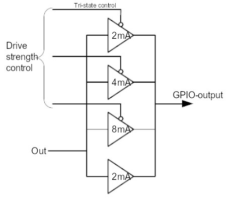
Current value
The current value specifies the maximum current under which the pad will still meet the specification.
Current value is not the current that the pad will deliver, and is not a current limit.
The pad output is a voltage source:
-
If set high, the pad will try to drive the output to the rail voltage (3.3V)
-
If set low, the pad will try to drive the output to ground (0V)
The pad will try to drive the output high or low. Success will depend on the requirements of what is connected. If the pad is shorted to ground, it will not be able to drive high. It will try to deliver as much current as it can, and the current is only limited by the internal resistance.
If the pad is driven high and it is shorted to ground, in due time it will fail. The same holds true if you connect it to 3.3V and drive it low.
Meeting the specification is determined by the guaranteed voltage levels. Because the pads are digital, there are two voltage levels, high and low. The I/O ports have two parameters which deal with the output level:
-
VOL, the maximum low-level voltage (0.14V at 3.3V VDD IO)
-
VOH, the minimum high-level voltage (3.0V at 3.3V VDD IO)
VOL=0.14V means that if the output is Low, it will be <= 0.14V. VOH=3.0V means that if the output is High, it will be >= 3.0V.
As an example, a drive strength of 16mA means that if you set the pad high, you can draw up to 16mA, and the output voltage is guaranteed to be >=VOH. This also means that if you set a drive strength of 2mA and you draw 16mA, the voltage will not be VOH but lower. In fact, it may not be high enough to be seen as high by an external device.
There is more information on the physical characteristics of the GPIO pins.
|
Note
|
On the Compute Module devices, it is possible to change the VDD IO from the standard 3.3V. In this case, VOL and VOH will change according to the table in the GPIO section. |
The Raspberry Pi 3.3V supply was designed with a maximum current of ~3mA per GPIO pin. If you load each pin with 16mA, the total current is 272mA. The 3.3V supply will collapse under that level of load. Big current spikes will happen, especially if you have a capacitive load. Spikes will bounce around all the other pins near them. This is likely to cause interference with the SD card, or even the SDRAM behaviour.
Safe current
All the electronics of the pads are designed for 16mA. This is a safe value under which you will not damage the device. Even if you set the drive strength to 2mA and then load it so 16mA comes out, this will not damage the device. Other than that, there is no guaranteed maximum safe current.
GPIO addresses
-
0x 7e10 002c PADS (GPIO 0-27)
-
0x 7e10 0030 PADS (GPIO 28-45)
-
0x 7e10 0034 PADS (GPIO 46-53)
| Bits | Field name | Description | Type | Reset |
|---|---|---|---|---|
31:24 |
PASSWRD |
Must be 0x5A when writing; accidental write protect password |
W |
0 |
23:5 |
Reserved – Write as 0, read as don’t care |
|||
4 |
SLEW |
Slew rate; 0 = slew rate limited; 1 = slew rate not limited |
RW |
0x1 |
3 |
HYST |
Enable input hysteresis; 0 = disabled; 1 = enabled |
RW |
0x1 |
2:0 |
DRIVE |
Drive strength, see breakdown list below |
RW |
0x3 |
Beware of Simultaneous Switching Outputs (SSO) limitations which are device-dependent as well as dependent on the quality and layout of the PCB, the amount and quality of the decoupling capacitors, the type of load on the pads (resistance, capacitance), and other factors beyond the control of Raspberry Pi.
Industrial use of the Raspberry Pi
Edit this on GitHub
Raspberry Pi is often used as part of another product. This documentation describes some extra facilities available to use other capabilities of your Raspberry Pi.
One-time programmable settings
There are a number of OTP values that can be used. To see a list of all the OTP values, run the following command:
$ vcgencmd otp_dumpSome interesting lines from this dump are:
-
28 – Serial number
-
29 – Ones complement of serial number
-
30 – Board revision number
Also, from 36 to 43 (inclusive), there are eight rows of 32 bits available for the customer.
|
Note
|
On BCM2712 devices these numbers are different. Row 31 is the serial number and row 32 is the board revision number. The customer rows are 77 to 84 inclusive. |
Some of these rows can be programmed with vcmailbox. This is a Linux driver interface to the firmware which will handle the programming of the rows. To do this, please refer to the documentation, and the vcmailbox example application.
The vcmailbox application can be used directly from the command line on Raspberry Pi OS. An example usage would be:
$ vcmailbox 0x00010004 8 8 0 0…which will return something like:
0x00000020 0x80000000 0x00010004 0x00000008 0x800000008 0xnnnnnnnn 0x00000000 0x00000000
The above uses the mailbox property interface GET_BOARD_SERIAL with a request size of 8 bytes and response size of 8 bytes (sending two integers for the request 0, 0). The response to this will be two integers (0x00000020 and 0x80000000) followed by the tag code, the request length, the response length (with the 31st bit set to indicate that it is a response) then the 64-bit serial number (where the MS 32 bits are always 0).
Write and read customer OTP values
|
Warning
|
The OTP values are one-time programmable. After a bit has been changed from 0 to 1, it can’t be changed back. |
To set the customer OTP values you will need to use the SET_CUSTOMER_OTP (0x38021) tag as follows:
$ vcmailbox 0x00038021 [8 + number * 4] [8 + number * 4] [start_num] [number] [value] [value] [value] ...-
start_num= the first row to program from 0-7 -
number= number of rows to program -
value= each value to program
So, to program OTP customer rows 4, 5, and 6 to 0x11111111, 0x22222222, 0x33333333 respectively, you would use:
$ vcmailbox 0x00038021 20 20 4 3 0x11111111 0x22222222 0x33333333This will then program rows 40, 41, and 42.
To read the values back, you can use:
$ vcmailbox 0x00030021 20 20 4 3 0 0 0This should display:
0x0000002c 0x80000000 0x00030021 0x00000014 0x80000014 0x00000000 0x00000003 0x11111111 0x22222222 0x33333333
If you’d like to integrate this functionality into your own code, you should be able to achieve this by using the vcmailbox.c code as an example.
Locking OTP on non-BCM2712 devices
It is possible to lock the OTP changes to avoid them being edited again.
This can be done using a special argument with the OTP write mailbox:
$ vcmailbox 0x00038021 8 8 0xffffffff 0xaffe0000When locked, the customer OTP values can no longer be altered. Note that this locking operation is irreversible.
Locking OTP on BCM2712 devices
The customer region can be marked as read only with the following command.
$ vcmailbox 0x00030086 4 4 0OTP is only locked until the device is reset, so OTP locks need to be reapplied on every boot.
Making customer OTP bits unreadable on non-BCM2712 devices
It is possible to prevent the customer OTP bits from being read at all. This can be done using a special argument with the OTP write mailbox:
$ vcmailbox 0x00038021 8 8 0xffffffff 0xaffebabeThis operation is unlikely to be useful for the vast majority of users, and is irreversible.
Customer MAC addresses on BCM2712 devices
On BCM2712 devices the Ethernet, Wi-Fi and Bluetooth MAC addresses are set in OTP memory. These values can change with customer values.
Get customer mac address vcmailbox 0x00030082/3/4 6 6 0 0, where 2 is Ethernet, 3 is Wi-Fi and 4 is Bluetooth:
$ vcmailbox 0x00030083 6 6 0 0
0x00000020 0x80000000 0x00030083 0x00000006 0x80000006 0xddccbbaa 0x0000ffee 0x00000000
In order to set a customer MAC address, it has to be sent as two 32 words with the bytes in the right order. You can run a command to check it’s formatted properly:
$ vcmailbox 0x00030085 6 6 0x44332211 0x6655Check the log to see if the MAC address matches your expectations:
$ sudo vclog -m
1057826.701: read mac address 11:22:33:44:55:66
A multicast address is not considered valid. The least significant bit in the most significant octet of a MAC address is the multicast bit, so make sure this is not set.
You can then set the customer MAC address with the command vcmailbox 0x00038082/3/4 6 6 <row1> <row0>:
$ vcmailbox 0x00038082 6 6 0x44332211 0x6655If a customer MAC address is set to ff:ff:ff:ff:ff:ff, then it’s ignored.
Device-specific private key
Devices that use the Broadcom BCM2712 processor have 16 rows of OTP data (512 bits) to support filesystem encryption. Devices that do not use BCM2712 have 8 rows of OTP (256 bits) available for use as a device-specific private key.
These rows can be programmed and read using similar vcmailbox commands to those used for managing customer OTP rows. If
secure-boot / file-system encryption is not required, then the device private key rows can be used to store general-purpose information.
-
The device private key rows can only be read via the
vcmailboxcommand which requires access to/dev/vciowhich is restricted to thevideogroup on Raspberry Pi OS. -
Raspberry Pi computers do not have a hardware protected key store. It is recommended that this feature is used in conjunction with Secure Boot in order to restrict access to this data.
-
Raspberry Pi OS does not support an encrypted root-filesystem.
See Cryptsetup for more information about open-source disk encryption.
Program a key into OTP with rpi-otp-private-key
|
Note
|
The rpi-otp-private-key script only works on devices that use the Broadcom BCM2711 or BCM2712 processors.
|
The rpi-otp-private-key script wraps the device private key vcmailbox APIs to make it easier to read and write a key in the OpenSSL format.
|
Note
|
The usbboot repository contains all the tools you need, including rpi-eeprom as a Git submodule.
|
Read the 32-byte key as a 64-character hex number:
$ cd usbboot/tools
$ rpi-otp-private-key
Example output:
f8dbc7b0a4fcfb1d706e298ac9d0485c2226ce8df7f7596ac77337bd09fbe160
Writes a 32-byte randomly generated number to the device private key.
|
Warning
|
This operation cannot be undone. |
$ rpi-otp-private-key -w $(openssl rand -hex 32)|
Note
|
To specify the number of OTP rows to use, pass -l <word count>. To specify a start location in the key store, pass -o <word offset>.
|
Mailbox API for reading/writing the key
Read all of the rows.
$ vcmailbox 0x00030081 40 40 0 8 0 0 0 0 0 0 0 0Example output:
0x00000040 0x80000000 0x00030081 0x00000028 0x80000028 0x00000000 0x00000008 0xf8dbc7b0 0xa4fcfb1d 0x706e298a 0xc9d0485c 0x2226ce8d 0xf7f7596a 0xc77337bd 0x09fbe160 0x00000000
Write all of the row (replace the trailing eight zeros with the key data):
$ vcmailbox 0x00038081 40 40 0 8 0 0 0 0 0 0 0 0Write the key shown in the previous example:
$ vcmailbox 0x38081 40 40 0 8 0xf8dbc7b0 0xa4fcfb1d 0x706e298a 0xc9d0485c 0x2226ce8d 0xf7f7596a 0xc77337bd 0x09fbe160OTP register and bit definitions
Edit this on GitHub
All SoCs used by the Raspberry Pi range have a inbuilt one-time programmable (OTP) memory block. A few locations have factory-programmed data.
OTP memory size:
-
non-BCM2712 devices: 66 32-bit values
-
BCM2712 devices: 192 32-bit values
To display the contents of the OTP, run the following command:
$ vcgencmd otp_dumpOTP registers on non-BCM2712 devices
This list contains the publicly available information on the registers. If a register or bit is not defined here, then it is not public.
16-
OTP control register – BCM2711
-
Bit 26: disables VC JTAG
-
Bit 27: disables VC JTAG
-
17-
bootmode register
-
Bit 1: sets the oscillator frequency to 19.2 MHz
-
Bit 3: enables pull ups on the SDIO pins
-
Bit 15: disables ROM RSA key 0 – (secure boot enabled if set) (BCM2711)
-
Bit 19: enables GPIO bootmode
-
Bit 20: sets the bank to check for GPIO bootmode
-
Bit 21: enables booting from SD card
-
Bit 22: sets the bank to boot from
-
Bit 28: enables USB device booting
-
Bit 29: enables USB host booting (ethernet and mass storage)
-
|
Note
|
On BCM2711 the bootmode is defined by the bootloader EEPROM configuration instead of OTP. |
18-
copy of bootmode register
28-
serial number
29-
~(serial number)
3033-
board revision extended – the meaning depends on the board model. This is available via device-tree in
/proc/device-tree/chosen/rpi-boardrev-extand for testing purposes this OTP value can be temporarily overridden by settingboard_rev_extinconfig.txt.-
Compute Module 4
-
Bit 30: Whether the Compute Module has a Wi-Fi module fitted
-
0 – Wi-Fi
-
1 – No Wi-Fi
-
-
Bit 31: Whether the Compute Module has an EMMC module fitted
-
0 – EMMC
-
1 – No EMMC (Lite)
-
-
-
Raspberry Pi 400
-
Bits 0-7: The default keyboard country code used by piwiz
-
-
-
35 -
High 32 bits of 64-bit serial number
36-4345-
MPG2 decode key
46-
WVC1 decode key
47-54-
SHA256 of RSA public key for secure-boot
55-
secure-boot flags (reserved for use by the bootloader)
56-63-
256-bit device-specific private key
64-65-
MAC address; if set, system will use this in preference to the automatically generated address based on the serial number
66-
advanced boot register (not BCM2711)
-
Bits 0-6: GPIO for ETH_CLK output pin
-
Bit 7: enables ETH_CLK output
-
Bits 8-14: GPIO for LAN_RUN output pin
-
Bit 15: enables LAN_RUN output
-
Bit 24: extends USB HUB timeout parameter
-
Bit 25: ETH_CLK frequency:
-
0 – 25 MHz
-
1 – 24 MHz
-
-
1Also contains bits to disable overvoltage, OTP programming, and OTP reading.
OTP Registers on BCM2712 devices
This list contains the publicly available information on the registers. If a register or bit is not defined here, then it is not public.
22-
bootmode register
-
Bit 1: Boot from SD card
-
Bits 2-4: Booting from SPI EEPROM (and which GPIOs)
-
Bit 10: Disable booting from SD card
-
Bit 11: Disable booting from SPI
-
Bit 12: Disable booting from USB
-
23-
copy of bootmode register
29-
advanced boot mode
-
Bits 0-7: GPIO for SD card detect
-
Bits 8-15: GPIO to use for RPIBOOT
-
31-
lower 32 bits of serial number
3233-
board attributes – the meaning depends on the board model. This is available via device-tree in
/proc/device-tree/chosen/rpi-boardrev-ext 35-
upper 32 bits of serial number The full 64 bit serial number is available in
/proc/device-tree/serial-number 50-51-
Ethernet MAC address This is passed to the operating system in the Device Tree, for example,
/proc/device-tree/axi/pcie@120000/rp1/ethernet@100000/local-mac-address 52-53-
Wi-Fi MAC address This is passed to the operating system in the Device Tree, for example,
/proc/device-tree/axi/mmc@1100000/wifi@1/local-mac-address 54-55-
Bluetooth MAC address This is passed to the operating system in the Device Tree, for example,
/proc/device-tree/soc/serial@7d50c000/bluetooth/local-bd-address 77-8486-
board country – The default keyboard country code used by piwiz If set, this is available via Device Tree in
/proc/device-tree/chosen/rpi-country-code 87-88-
customer Ethernet MAC address Overrides OTP rows 50-51 if set
89-90-
customer Wi-Fi MAC address Overrides OTP rows 52-53 if set
89-90-
customer Bluetooth MAC address Overrides OTP rows 54-55 if set
109-114-
Factory device UUID Currently a 16-digit numerical id which should match the bar code on the device. Padded with zero characters and c40 encoded.
This is available via device-tree in /proc/device-tree/chosen/rpi-duid.
Raspberry Pi connector for PCIe
Edit this on GitHub

Raspberry Pi 5 has an FPC connector on the left side of the board. This connector breaks out a PCIe Gen 2.0 ×1 interface for fast peripherals.
To connect a PCIe HAT+ device, connect it to your Raspberry Pi. Your Raspberry Pi should automatically detect the device. To connect a non-HAT+ device, connect it to your Raspberry Pi, then manually enable PCIe.
For more information about the PCIe FPC connector pinout and other details needed to create third-party devices, accessories, and HATs, see the Raspberry Pi Connector for PCIe standards document. It should be read alongside the Raspberry Pi HAT+ Specification.
|
Note
|
Only certain devices support enumeration of PCIe devices behind a switch. |
Enable PCIe
By default, the PCIe connector is not enabled unless connected to a HAT+ device. To enable the connector, add the following line to /boot/firmware/config.txt:
dtparam=pciex1Reboot with sudo reboot for the configuration changes to take effect.
|
Note
|
You can also use the alias nvme.
|
Boot from PCIe
By default, Raspberry Pi devices do not boot from PCIe storage. To enable boot from PCIe, change the BOOT_ORDER in the bootloader configuration. Edit the EEPROM configuration with the following command:
$ sudo rpi-eeprom-config --editReplace the BOOT_ORDER line with the following line:
BOOT_ORDER=0xf416To boot from a non-HAT+ device, also add the following line:
PCIE_PROBE=1After saving your changes, reboot your Raspberry Pi with sudo reboot to update the EEPROM.
PCIe Gen 3.0
|
Warning
|
The Raspberry Pi 5 is not certified for Gen 3.0 speeds. PCIe Gen 3.0 connections may be unstable. |
By default, Raspberry Pi 5 uses Gen 2.0 speeds (5 GT/s). Use one of the following approaches to enable Gen 3.0 (8 GT/s) speeds:
-
raspi-config -
config.txt
Run the following command to open the Raspberry Pi Configuration CLI:
$ sudo raspi-configComplete the following steps to enable PCIe Gen 3.0 speeds:
-
Select
Advanced Options. -
Select
PCIe Speed. -
Choose
Yesto enable PCIe Gen 3 mode. -
Select
Finishto exit. -
Reboot your Raspberry Pi with
sudo rebootfor your changes to take effect.
To enable PCIe Gen 3.0 speeds, add the following line to /boot/firmware/config.txt:
dtparam=pciex1_gen=3Reboot your Raspberry Pi with sudo reboot for these settings to take effect.
Power button
Edit this on GitHub
|
Note
|
This section only applies to Raspberry Pi models with a power button, such as the Raspberry Pi 5. |
When you plug your Raspberry Pi into power for the first time, it will automatically turn on and boot into the operating system without having to push the button.
If you run Raspberry Pi Desktop, you can initiate a clean shutdown by briefly pressing the power button. A window will appear asking whether you want to shutdown, reboot, or logout.
Select an option or press the power button again to initiate a clean shutdown.
|
Note
|
If you run Raspberry Pi Desktop, you can press the power button twice in quick succession to shut down. If you run Raspberry Pi OS Lite without a desktop, press the power button a single time to initiate a shutdown. |
Restart
If the Raspberry Pi board is turned off, but still connected to power, pressing the power button restarts the board.
|
Note
|
Resetting the Power Management Integrated Circuit (PMIC) can also restart the board. Connecting a HAT can reset the PMIC. Always disconnect your device from the power supply before connecting a HAT. |
Add your own power button
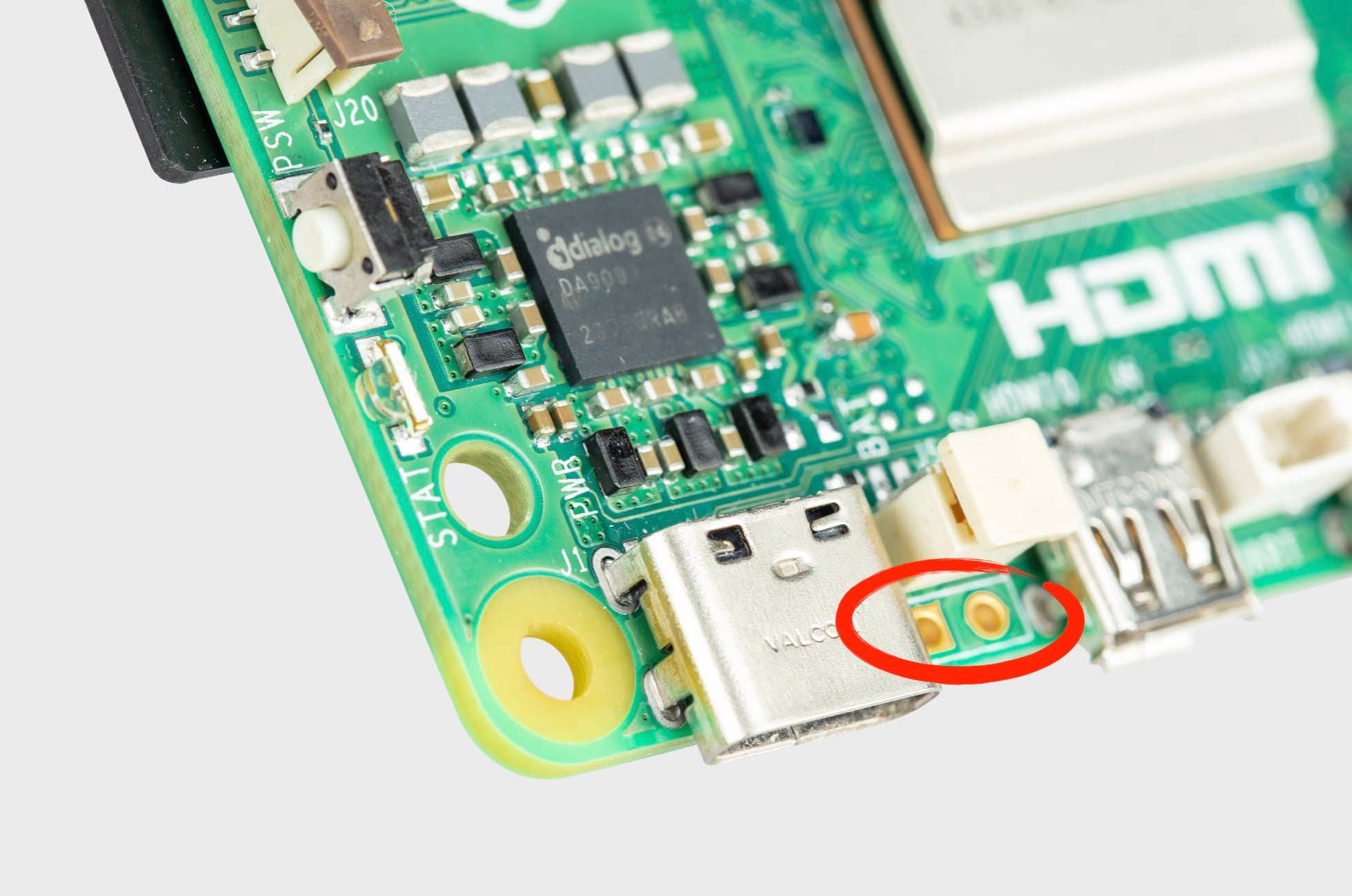
The J2 jumper is located between the RTC battery connector and the board edge. This breakout allows you to add your own power button to Raspberry Pi 5 by adding a Normally Open (NO) momentary switch bridging the two pads. Briefly closing this switch will perform the same actions as the onboard power button.
Power supply
Edit this on GitHub
The power supply requirements differ by Raspberry Pi model. All models require a 5.1V supply, but the current required generally increases according to model. All models up to the Raspberry Pi 3 require a micro USB power connector, while Raspberry Pi 4, Raspberry Pi 400, and Raspberry Pi 5 use a USB-C connector.
The current consumed by each Raspberry Pi depends on the peripherals connected.
Recommended power supplies
For Raspberry Pi 1, Raspberry Pi 2, and Raspberry Pi 3, we recommend the 2.5A micro USB supply. For Raspberry Pi 4 and Raspberry Pi 400, we recommend the 3A USB-C Supply for Raspberry Pi 4. For Raspberry Pi 5, we recommend the 27 W USB-C Power Supply.
|
Note
|
No Raspberry Pi models support USB-PPS. |
|
Note
|
If you use a third-party USB-PD multi-port power supply, plugging an additional device into the supply when your Raspberry Pi is connected causes a renegotiation between the supply and the Raspberry Pi. If the Raspberry Pi is powered, this happens seamlessly. If the Raspberry Pi is powered down, this renegotiation may cause the Raspberry Pi to boot. |
Power over Ethernet (PoE) connector
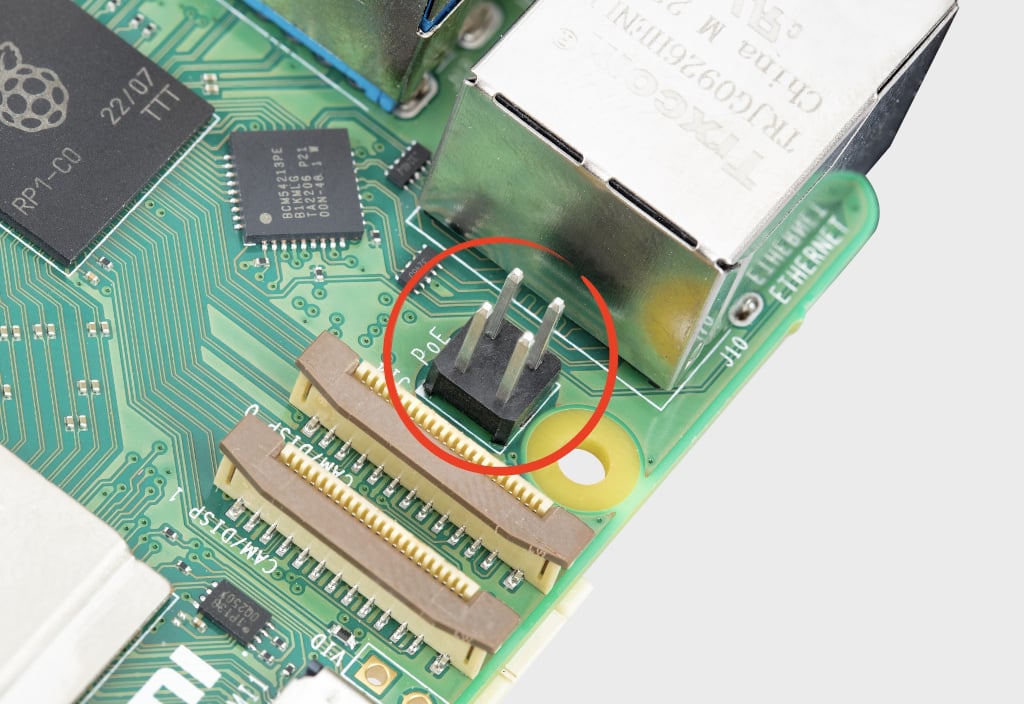
The Ethernet jack on Raspberry Pi 5 is PoE+ capable, supporting the IEEE 802.3at-2009 PoE standard.
The Ethernet jack on Raspberry Pi 4B and 3B+ is PoE capable, supporting the IEEE 802.3af-2003 PoE standard.
Typical power requirements
| Product | Recommended PSU current capacity | Maximum total USB peripheral current draw | Typical bare-board active current consumption |
|---|---|---|---|
Raspberry Pi 1 Model A |
700mA |
500mA |
200mA |
Raspberry Pi 1 Model B |
1.2A |
500mA |
500mA |
Raspberry Pi 1 Model A+ |
700mA |
500mA |
180mA |
Raspberry Pi 1 Model B+ |
1.8A |
1.2A |
330mA |
Raspberry Pi 2 Model B |
1.8A |
1.2A |
350mA |
Raspberry Pi 3 Model B |
2.5A |
1.2A |
400mA |
Raspberry Pi 3 Model A+ |
2.5A |
Limited by PSU, board, and connector ratings only. |
350mA |
Raspberry Pi 3 Model B+ |
2.5A |
1.2A |
500mA |
Raspberry Pi 4 Model B |
3.0A |
1.2A |
600mA |
Raspberry Pi 5 |
5.0A |
1.6A (600mA if using a 3A power supply) |
800mA |
Pi 400 |
3.0A |
1.2A |
800mA |
Pi 500 |
5.0A |
1.6A (600mA if using a 3A power supply) |
800mA |
Pi 500+ |
5.0A |
1.6A |
800mA (with LEDs off and SSD inactive) |
Zero |
1.2A |
Limited by PSU, board, and connector ratings only |
100mA |
Zero W |
1.2A |
Limited by PSU, board, and connector ratings only. |
150mA |
Zero 2 W |
2A |
Limited by PSU, board, and connector ratings only. |
350mA |
|
Note
|
The Raspberry Pi 5 provides 1.6A of power to downstream USB peripherals when connected to a power supply capable of 5A at +5V (25W). When connected to any other compatible power supply, the Raspberry Pi 5 restricts downstream USB devices to 600mA of power. |
Most Raspberry Pis provide enough current to USB peripherals to power most USB devices, including keyboards, mice, and adapters. However, some devices require additional current, including modems, external disks, and high-powered antenna. To connect a USB device with power requirements that exceed the values specified in the table above, connect it using an externally-powered USB hub.
The power requirements of the Raspberry Pi increase as you make use of the various interfaces on the Raspberry Pi. Combined, the GPIO pins can draw 50mA safely; each pin can individually draw up to 16mA. The HDMI port uses 50mA. The Camera Module requires 250mA. USB keyboards and mice can take as little as 100mA or as much as 1000mA. Check the power rating of the devices you plan to connect to the Raspberry Pi and purchase a power supply accordingly. If you’re not sure, use an externally-powered USB hub.
Run the following command to check the status of power output to the USB ports:
$ vcgencmd get_config usb_max_current_enableThe following table describes the amount of current (in amps) drawn by different Raspberry Pi models during various workloads:
Raspberry Pi 1B+ |
Raspberry Pi 2B |
Raspberry Pi 3B |
Raspberry Pi Zero |
Raspberry Pi 4B |
||
Boot |
Max |
0.26 |
0.40 |
0.75 |
0.20 |
0.85 |
Avg |
0.22 |
0.22 |
0.35 |
0.15 |
0.7 |
|
Idle |
Avg |
0.20 |
0.22 |
0.30 |
0.10 |
0.6 |
Video playback (H.264) |
Max |
0.30 |
0.36 |
0.55 |
0.23 |
0.85 |
Avg |
0.22 |
0.28 |
0.33 |
0.16 |
0.78 |
|
Stress |
Max |
0.35 |
0.82 |
1.34 |
0.35 |
1.25 |
Avg |
0.32 |
0.75 |
0.85 |
0.23 |
1.2 |
|
Halt current |
0.10 |
0.055 |
0.023 |
|
Note
|
These measurements used a standard Raspberry Pi OS image (current as of 26 Feb 2016, or June 2019 for the Raspberry Pi 4), at room temperature, with the Raspberry Pi connected to a HDMI monitor, USB keyboard, and USB mouse. The Raspberry Pi 3 Model B was connected to a wireless LAN access point, the Raspberry Pi 4 was connected to Ethernet. All these power measurements are approximate and do not take into account power consumption from additional USB devices; power consumption can easily exceed these measurements if multiple additional USB devices or a HAT are connected to the Raspberry Pi. |
Decrease Raspberry Pi 5 wattage when turned off
By default, the Raspberry Pi 5 consumes around 1 W to 1.4 W of power when turned off. This can be decreased by manually editing the EEPROM configuration with sudo rpi-eeprom-config -e. Modify the settings to add:
POWER_OFF_ON_HALT=1This should drop the power consumption when powered down to around 0.01W.
Power supply warnings
On all models of Raspberry Pi since the Raspberry Pi B+ (2014) except the Zero range, there is low-voltage detection circuitry that will detect if the supply voltage drops below 4.63V (±5%). This will result in an entry being added to the kernel log.
If you see warnings, switch to a higher quality power supply and cable. Low quality power supplies can corrupt storage or cause unpredictable behaviour within the Raspberry Pi.
Voltages can drop for a variety of reasons. You may have plugged in too many high-demand USB devices. The power supply could be inadequate. Or the power supply cable could use wires that are too thin.
Power supplies and Raspberry Pi OS
The bootloader passes information about the power supply via device-tree /proc/device-tree/chosen/power. Users will typically not read this directly.
- max_current
-
The max current in mA
- uspd_power_data_objects
-
A dump of the PDOs – debug for advanced users
- usb_max_current_enable
-
Whether the current limiter was set to high or low
- usb_over_current_detected
-
Whether any USB over current occurred during boot before transferring control to the OS
- reset_event
-
The PMIC reset reason, for example, watchdog, over- or under-voltage, over-temperature
The PMIC has built-in ADCs that, among other things, can measure the supply voltage EXT5V_V. Use the following command to view ADC measurements:
$ vcgencmd pmic_read_adcYou can’t see USB current or anything else connected directly to 5V, because this bypasses the PMIC. You should not expect this to add up to the wattage of the source power supply. However, it can be useful to monitor things like the core voltage.
Back-powering
The USB specification requires that USB devices must not supply current to upstream devices. If a USB device does supply current to an upstream device, then this is called back-powering. Often this happens when a badly-made powered USB hub is connected, and will result in the powered USB hub supplying power to the host Raspberry Pi. This is not recommended since the power being supplied to the Raspberry Pi via the hub will bypass the protection circuitry built into the Raspberry Pi, leaving it vulnerable to damage in the event of a power surge.
Real Time Clock (RTC)
Edit this on GitHub
The Raspberry Pi 5 includes an RTC module. This can be battery powered through the J5 (BAT) connector on the board. When the components are facing up and the logo is in the correct orientation, the J5 connector is located towards the near left corner of the board and to the right of the USB-C power connector.

You can set a wake alarm, which switches the board to a very low-power state (approximately 3 mA). When the alarm time is reached, the board powers back on. This can be useful for periodic jobs like time-lapse imagery.
To support the low-power mode for wake alarms:
-
Edit the bootloader configuration.
$ sudo -E rpi-eeprom-config --edit -
Add the following two lines.
POWER_OFF_ON_HALT=1
WAKE_ON_GPIO=0
You can test the functionality with:
$ echo +600 | sudo tee /sys/class/rtc/rtc0/wakealarm
$ sudo halt
This command halts the board into a very low-power state, then wakes and restarts after 10 minutes.
The RTC also provides the time on boot, for example, in dmesg, for use cases that lack access to NTP:
[ 1.295799] rpi-rtc soc:rpi_rtc: setting system clock to 2023-08-16T15:58:50 UTC (1692201530)
|
Note
|
The RTC is still usable even when there’s no backup battery attached to the J5 connector. |
Add a backup battery

The official battery part is a rechargeable lithium manganese coin cell, with a pre-fitted two-pin JST-SH plug and an adhesive mounting pad. This is suitable for powering the RTC when the main power supply for the board is disconnected. Since the current draw when powered down measures in single-digit µA, the retention time measures in months.
|
Note
|
We don’t recommend using a primary (non-rechargeable) lithium cell for the RTC. The RTC backup current consumption is higher than most dedicated RTC modules and results in a short service life. |
|
Warning
|
Don’t use a Lithium Ion cell for the RTC. |
Enable battery charging
The RTC is equipped with a constant-current (3 mA) constant-voltage charger.
Charging of the battery is disabled by default. There are sysfs files that show the charging voltage and limits:
$ grep . /sys/class/rtc/rtc0/charging_voltage*

/sys/class/rtc/rtc0/charging_voltage:0
/sys/class/rtc/rtc0/charging_voltage_max:4400000
/sys/class/rtc/rtc0/charging_voltage_min:1300000
To charge the battery at a set voltage, add rtc_bbat_vchg to /boot/firmware/config.txt:
dtparam=rtc_bbat_vchg=3000000Reboot with sudo reboot to use the new voltage setting. Check the sysfs files to ensure that the charging voltage was correctly set.
Disable battery charging
To stop charging, remove any lines that contain rtc_bbat_vchg from config.txt.
Serial peripheral interface (SPI)
Edit this on GitHub
Raspberry Pi computers are equipped with a number of SPI buses. SPI can be used to connect a wide variety of peripherals – displays, network controllers (Ethernet, CAN bus), UARTs, etc. These devices are best supported by kernel device drivers, but the spidev API allows userspace drivers to be written in a wide array of languages.
SPI hardware
Raspberry Pi Zero, 1, 2 and 3 have three SPI controllers:
-
SPI0, with two hardware chip selects, is available on the header of all Raspberry Pis; there is also an alternate mapping that is only available on Compute Modules. -
SPI1, with three hardware chip selects, is available on all Raspberry Pi models except the original Raspberry Pi 1 Model A and Model B. -
SPI2, also with three hardware chip selects, is only available on Compute Module 1, 3 and 3+.
On the Raspberry Pi 4, 400 and Compute Module 4 there are four additional SPI buses: SPI3 to SPI6, each with two hardware chip selects. These extra SPI buses are available via alternate function assignments on certain GPIO pins. For more information, see the BCM2711 Arm peripherals datasheet.
Chapter 10 in the BCM2835 Arm peripherals datasheet describes the main controller. Chapter 2.3 describes the auxiliary controller.
Pin/GPIO mappings
SPI0
| SPI function | Header pin | Broadcom pin name | Broadcom pin function |
|---|---|---|---|
|
19 |
|
|
|
21 |
|
|
|
23 |
|
|
|
24 |
|
|
|
26 |
|
|
SPI0 alternate mapping (Compute Modules only, except CM4)
| SPI function | Broadcom pin name | Broadcom pin function |
|---|---|---|
|
|
|
|
|
|
|
|
|
|
|
|
|
|
|
SPI1
| SPI function | Header pin | Broadcom pin name | Broadcom pin function |
|---|---|---|---|
|
38 |
|
|
|
35 |
|
|
|
40 |
|
|
|
12 |
|
|
|
11 |
|
|
|
36 |
|
|
SPI2 (Compute Modules only, except CM4)
| SPI function | Broadcom pin name | Broadcom pin function |
|---|---|---|
|
|
|
|
|
|
|
|
|
|
|
|
|
|
|
|
|
|
SPI3 (BCM2711 only)
| SPI function | Header pin | Broadcom pin name | Broadcom pin function |
|---|---|---|---|
|
03 |
|
|
|
28 |
|
|
|
05 |
|
|
|
27 |
|
|
|
18 |
|
|
SPI4 (BCM2711 only)
| SPI function | Header pin | Broadcom pin name | Broadcom pin function |
|---|---|---|---|
|
31 |
|
|
|
29 |
|
|
|
26 |
|
|
|
07 |
|
|
|
22 |
|
|
Master modes
Signal name abbreviations:
- SCLK
-
serial clock
- CE
-
chip enable (often called chip select)
- MOSI
-
master out slave in
- MISO
-
master in slave out
- MOMI
-
master out master in
Standard mode
In Standard SPI mode the peripheral implements the standard three-wire serial protocol (SCLK, MOSI and MISO).
Bidirectional mode
In bidirectional SPI mode the same SPI standard is implemented, except that a single wire is used for data (MOMI) instead of the two used in standard mode (MISO and MOSI). In this mode, the MOSI pin serves as MOMI pin.
Low speed serial interface (LoSSI) mode
The LoSSI standard allows issuing of commands to peripherals (LCD) and to transfer data to and from them. LoSSI commands and parameters are 8 bits long, but an extra bit is used to indicate whether the byte is a command or parameter/data. This extra bit is set high for data and low for a command. The resulting 9-bit value is serialised to the output. LoSSI is commonly used with MIPI DBI type C compatible LCD controllers.
|
Note
|
Some commands trigger an automatic read by the SPI controller, so this mode cannot be used as a multipurpose 9-bit SPI. |
Speed
The clock divider (CDIV) field of the CLK register sets the SPI clock speed:
- SCLK
-
Core Clock / CDIV
If CDIV is set to 0, the divisor is 65536. The divisor must be a multiple of 2, with odd numbers rounded down. Note that not all possible clock rates are usable because of analogue electrical issues (rise times, drive strengths, etc).
See the Linux driver section for more info.
Chip selects
Setup and hold times related to the automatic assertion and de-assertion of the CS lines when operating in DMA mode are as follows:
-
The CS line will be asserted at least three core clock cycles before the msb of the first byte of the transfer.
-
The CS line will be de-asserted no earlier than one core clock cycle after the trailing edge of the final clock pulse.
SPI software
Linux driver
The default Linux driver is spi-bcm2835.
SPI0 is disabled by default. To enable it, use raspi-config, or ensure the line dtparam=spi=on is not commented out in /boot/firmware/config.txt. By default it uses two chip select lines, but this can be reduced to one using dtoverlay=spi0-1cs. There is also dtoverlay=spi0-2cs; without any parameters it is equivalent to dtparam=spi=on.
To enable SPI1, you can use 1, 2 or 3 chip select lines. Add the appropriate lines to /boot/firmware/config.txt:"
#1 chip select
dtoverlay=spi1-1cs
#2 chip select
dtoverlay=spi1-2cs
#3 chip select
dtoverlay=spi1-3cs
Similar overlays exist for SPI2, SPI3, SPI4, SPI5 and SPI6.
The driver does not make use of the hardware chip select lines because of some limitations. Instead, it can use an arbitrary number of GPIOs as software/GPIO chip selects. This means you are free to choose any spare GPIO as a CS line, and all of these SPI overlays include that control – see /boot/firmware/overlays/README for details, or run (for example) dtoverlay -h spi0-2cs (dtoverlay -a | grep spi might be helpful to list them all).
Speed
The driver supports all speeds which are even integer divisors of the core clock, although as said above not all of these speeds will support data transfer due to limits in the GPIOs and in the devices attached. As a rule of thumb, anything over 50 MHz is unlikely to work, but your mileage may vary.
Supported mode bits
- SPI_CPOL
-
clock polarity
- SPI_CPHA
-
clock phase
- SPI_CS_HIGH
-
chip select active high
- SPI_NO_CS
-
1 device per bus, no Chip select
- SPI_3WIRE
-
bidirectional mode, data in and out pin shared
Bidirectional mode, also called 3-wire mode, is supported by the spi-bcm2835 kernel module. Please note that in this mode, either the tx or rx field of the spi_transfer struct must be a NULL pointer, since only half-duplex communication is possible. Otherwise, the transfer will fail. The spidev_test.c source code does not consider this correctly, and therefore does not work at all in 3-wire mode.
Transfer modes
Interrupt mode is supported on all SPI buses. SPI0, and SPI3-6 also support DMA transfers.
SPI driver latency
This thread discusses latency problems.
spidev
spidev presents an ioctl-based userspace interface to individual SPI CS lines. Device Tree is used to indicate whether a CS line is going to be driven by a kernel driver module or managed by spidev on behalf of the user; it is not possible to do both at the same time. Note that Raspberry Pi’s own kernels are more relaxed about the use of Device Tree to enable spidev – the upstream kernels print warnings about such usage, and ultimately may prevent it altogether.
Use spidev from C
There is a loopback test program in the Linux documentation that can be used as a starting point. See the Troubleshooting section.
Use spidev from Python
There are several Python libraries that provide access to spidev, including spidev (pip install spidev – see https://pypi.org/project/spidev/) and SPI-Py (https://github.com/lthiery/SPI-Py).
Troubleshooting
Loopback test
This can be used to test SPI send and receive. Put a wire between MOSI and MISO. It does not test CE0 and CE1.
$ wget https://raw.githubusercontent.com/raspberrypi/linux/rpi-6.1.y/tools/spi/spidev_test.c
$ gcc -o spidev_test spidev_test.c
$ ./spidev_test -D /dev/spidev0.0
spi mode: 0
bits per word: 8
max speed: 500000 Hz (500 KHz)

FF FF FF FF FF FF
40 00 00 00 00 95
FF FF FF FF FF FF
FF FF FF FF FF FF
FF FF FF FF FF FF
DE AD BE EF BA AD
F0 0D
Some of the content above has been copied from the elinux SPI page, which also borrows from here. Both are covered by the CC-SA licence.
Universal Serial Bus (USB)
Edit this on GitHub
In general, every device supported by Linux can be used with a Raspberry Pi, although there are some limitations for models prior to Raspberry Pi 4.
Maximum power output
As with all computers, the USB ports on the Raspberry Pi supply a limited amount of power. Often problems with USB devices are caused by power issues. To rule out insufficient power as the cause of the problem, connect your USB devices to the Raspberry Pi using a powered hub.
| Model | Max power output of USB ports |
|---|---|
Raspberry Pi Zero, 1 |
500mA per port1 |
Raspberry Pi 2, 3, 4 |
1200mA total across all ports |
Raspberry Pi 5 |
600mA if using a 3A supply, 1600mA if using a 5A supply |
-
For the original Raspberry Pi 1 Model B the limit is 100mA per port.
Raspberry Pi 5
The Raspberry Pi 5 requires a good quality USB-C power supply capable of delivering 3A at +5V (15W) in order to boot. However, using such a supply will restrict current draw to peripherals. If you are using a power supply that cannot provide 5A at +5V on first boot you will be warned by the operating system that the current draw to peripherals will be restricted to 600mA.
For users who wish to drive high-power peripherals like hard drives and SSDs, while retaining margin for peak workloads, a USB-PD enabled power supply capable of supplying a 5A at +5V (25W) should be used. If the Raspberry Pi 5 firmware detects such a supply, it increases the USB current limit for peripherals to 1.6A, providing 5 W of extra power for downstream USB devices, and 5 W of extra onboard power budget.
|
Note
|
The power budget is shared between the USB ports and the fan header. |
Raspberry Pi 4
Raspberry Pi 4 offers two USB 3.0 ports and two USB 2.0 ports which are connected to a VL805 USB controller. The USB 2.0 lines on all four ports are connected to a single USB 2.0 hub within the VL805. This limits the total available bandwidth for USB 1.1 and USB 2.0 devices to that of a single USB 2.0 port.
On Raspberry Pi 4, the USB controller used on previous models is located on the USB type C port and is disabled by default.
Raspberry Pi Zero, 1, 2 and 3
Raspberry Pi 1 Model B+, Raspberry Pi 2, and Raspberry Pi 3 boards offer four USB 2.0 ports. Raspberry Pi Zero boards have one micro USB on-the-go (OTG) port.
The USB controller on models prior to Raspberry Pi 4 has only a basic level of support for certain devices, which presents a higher software processing overhead. It also supports only one root USB port: all traffic from connected devices is funnelled down this single bus, which operates at a maximum speed of 480Mbps.
The USB 2.0 specification defines three device speeds – low, full and high. Most mice and keyboards are low speed, most USB sound devices are full speed, and most video devices (webcams or video capture) are high speed.
Generally, there are no issues with connecting multiple high speed USB devices to a Raspberry Pi.
The software overhead incurred when talking to low- and full-speed devices means that there are limitations on the number of simultaneously active low- and full-speed devices. Small numbers of these types of devices connected to a Raspberry Pi will cause no issues.
Known USB issues
Interoperability with USB 3.0 hubs
There is an issue with USB 3.0 hubs in conjunction with the use of full- or low-speed devices, including most mice and keyboards. A bug in most USB 3.0 hub hardware means that the models prior to Raspberry Pi 4 cannot talk to full or low speed devices connected to a USB 3.0 hub.
USB 2.0 high speed devices, including USB 2.0 hubs, operate correctly when connected via a USB 3.0 hub.
Avoid connecting low or full speed devices into a USB 3.0 hub. As a workaround, plug a USB 2.0 hub into the downstream port of the USB 3.0 hub and connect the low-speed device, or use a USB 2.0 hub between the Raspberry Pi and the USB 3.0 hub, then plug low-speed devices into the USB 2.0 hub.
USB 1.1 webcams
Old webcams may be full-speed devices. Because these devices transfer a lot of data and incur additional software overhead, reliable operation is not guaranteed. As a workaround, try to use the camera at a lower resolution.
Esoteric USB sound cards
Expensive audiophile sound cards typically use large amounts of USB bandwidth. Reliable operation with 96 kHz/192 kHz DACs is not guaranteed. As a workaround, forcing the output stream to be CD quality (44.1 kHz/48 kHz 16-bit) will reduce the stream bandwidth to reliable levels.
Single TT USB hubs
USB 2.0 and 3.0 hubs have a mechanism for talking to full- or low-speed devices connected to their downstream ports called a transaction translator (TT). This device buffers high speed requests from the host and transmits them at full or low speed to the downstream device. Two configurations of hub are allowed by the USB specification: Single TT (one TT for all ports) and Multi TT (one TT per port). Because of a hardware limitation, if too many full- or low-speed devices are plugged into a single TT hub, the devices may behave unreliably. It is recommended to use a Multi TT hub to interface with multiple full and low speed devices. As a workaround, spread full- and low-speed devices out between the Raspberry Pi’s own USB port and the single TT hub.
Raspberry Pi revision codes
Edit this on GitHub
Each distinct Raspberry Pi model revision has a unique revision code. You can look up a Raspberry Pi’s revision code by running:
$ cat /proc/cpuinfoThe last three lines show the hardware type, the revision code, and the Raspberry Pi’s unique serial number. For example:
Hardware    : BCM2835
Revision    : a02082
Serial      : 00000000765fc593
|
Note
|
All Raspberry Pi computers report BCM2835, even those with BCM2836, BCM2837, BCM2711, and BCM2712 processors. You should not use this string to detect the processor. Decode the revision code using the information below, or cat /sys/firmware/devicetree/base/model. Depending on which kernel you’re running, your cpuinfo might also have a "Model" line, and might not have a "Hardware" line.
|
Old-style revision codes
The first set of Raspberry Pi models were given sequential hex revision codes from 0002 to 0015:
| Code | Model | Revision | RAM | Manufacturer |
|---|---|---|---|---|
0002 |
B |
1.0 |
256 MB |
Egoman |
0003 |
B |
1.0 |
256 MB |
Egoman |
0004 |
B |
2.0 |
256 MB |
Sony UK |
0005 |
B |
2.0 |
256 MB |
Qisda |
0006 |
B |
2.0 |
256 MB |
Egoman |
0007 |
A |
2.0 |
256 MB |
Egoman |
0008 |
A |
2.0 |
256 MB |
Sony UK |
0009 |
A |
2.0 |
256 MB |
Qisda |
000d |
B |
2.0 |
512 MB |
Egoman |
000e |
B |
2.0 |
512 MB |
Sony UK |
000f |
B |
2.0 |
512 MB |
Egoman |
0010 |
B+ |
1.2 |
512 MB |
Sony UK |
0011 |
CM1 |
1.0 |
512 MB |
Sony UK |
0012 |
A+ |
1.1 |
256 MB |
Sony UK |
0013 |
B+ |
1.2 |
512 MB |
Embest |
0014 |
CM1 |
1.0 |
512 MB |
Embest |
0015 |
A+ |
1.1 |
256 MB / 512 MB |
Embest |
New-style revision codes
With the launch of the Raspberry Pi 2, new-style revision codes were introduced. Rather than being sequential, each bit of the hex code represents a piece of information about the revision:
NOQuuuWuFMMMCCCCPPPPTTTTTTTTRRRR
| Part | Represents | Options |
|---|---|---|
N (bit 31) |
Overvoltage |
0: Overvoltage allowed |
1: Overvoltage disallowed |
||
O (bit 30) |
OTP Program1 |
0: OTP programming allowed |
1: OTP programming disallowed |
||
Q (bit 29) |
OTP Read1 |
0: OTP reading allowed |
1: OTP reading disallowed |
||
uuu (bits 26-28) |
Unused |
Unused |
W (bit 25) |
Warranty bit2 |
0: Warranty is intact |
1: Warranty has been voided by overclocking |
||
u (bit 24) |
Unused |
Unused |
F (bit 23) |
New flag |
1: new-style revision |
0: old-style revision |
||
MMM (bits 20-22) |
Memory size |
0: 256 MB |
1: 512 MB |
||
2: 1 GB |
||
3: 2 GB |
||
4: 4 GB |
||
5: 8 GB |
||
6: 16 GB |
||
7: Other3 |
||
CCCC (bits 16-19) |
Manufacturer |
0: Sony UK |
1: Egoman |
||
2: Embest |
||
3: Sony Japan |
||
4: Embest |
||
5: Stadium |
||
PPPP (bits 12-15) |
Processor |
0: BCM2835 |
1: BCM2836 |
||
2: BCM2837 |
||
3: BCM2711 |
||
4: BCM2712 |
||
TTTTTTTT (bits 4-11) |
Type |
0x00: A |
0x01: B |
||
0x02: A+ |
||
0x03: B+ |
||
0x04: 2B |
||
0x05: Alpha (early prototype) |
||
0x06: CM1 |
||
0x08: 3B |
||
0x09: Zero |
||
0x0a: CM3 |
||
0x0c: Zero W |
||
0x0d: 3B+ |
||
0x0e: 3A+ |
||
0x0f: Internal use only |
||
0x10: CM3+ |
||
0x11: 4B |
||
0x12: Zero 2 W |
||
0x13: 400 |
||
0x14: CM4 |
||
0x15: CM4S |
||
0x16: Internal use only |
||
0x17: 5 |
||
0x18: CM5 |
||
0x19: 500/500+ |
||
0x1a: CM5 Lite |
||
0x1b: CM0 |
||
RRRR (bits 0-3) |
Revision |
0, 1, 2, etc. |
1 Information on programming the OTP bits.
2 The warranty bit is never set on Raspberry Pi 4.
3 For a memory size of "Other", the actual memory capacity can be determined from the rpi-sdram-size-gbit firmware parameter.
New-style revision codes in use
|
Note
|
This list is not exhaustive – there may be codes in use that are not in this table. Please see the next section for best practices on using revision codes to identify boards. |
| Code | Model | Revision | RAM | Manufacturer |
|---|---|---|---|---|
900021 |
A+ |
1.1 |
512 MB |
Sony UK |
900032 |
B+ |
1.2 |
512 MB |
Sony UK |
a01040 |
2B |
1.0 |
1 GB |
Sony UK |
a01041 |
2B |
1.1 |
1 GB |
Sony UK |
a21041 |
2B |
1.1 |
1 GB |
Embest |
a02042 |
2B (with BCM2837) |
1.2 |
1 GB |
Sony UK |
a22042 |
2B (with BCM2837) |
1.2 |
1 GB |
Embest |
900061 |
CM1 |
1.1 |
512 MB |
Sony UK |
a02082 |
3B |
1.2 |
1 GB |
Sony UK |
a22082 |
3B |
1.2 |
1 GB |
Embest |
a32082 |
3B |
1.2 |
1 GB |
Sony Japan |
a52082 |
3B |
1.2 |
1 GB |
Stadium |
a22083 |
3B |
1.3 |
1 GB |
Embest |
900092 |
Zero |
1.2 |
512 MB |
Sony UK |
920092 |
Zero |
1.2 |
512 MB |
Embest |
900093 |
Zero |
1.3 |
512 MB |
Sony UK |
920093 |
Zero |
1.3 |
512 MB |
Embest |
a020a0 |
CM3 |
1.0 |
1 GB |
Sony UK |
a220a0 |
CM3 |
1.0 |
1 GB |
Embest |
9000c1 |
Zero W |
1.1 |
512 MB |
Sony UK |
a020d3 |
3B+ |
1.3 |
1 GB |
Sony UK |
a020d4 |
3B+ |
1.4 |
1 GB |
Sony UK |
9020e0 |
3A+ |
1.0 |
512 MB |
Sony UK |
9020e1 |
3A+ |
1.1 |
512 MB |
Sony UK |
a02100 |
CM3+ |
1.0 |
1 GB |
Sony UK |
a03111 |
4B |
1.1 |
1 GB |
Sony UK |
b03111 |
4B |
1.1 |
2 GB |
Sony UK |
c03111 |
4B |
1.1 |
4 GB |
Sony UK |
b03112 |
4B |
1.2 |
2 GB |
Sony UK |
c03112 |
4B |
1.2 |
4 GB |
Sony UK |
b03114 |
4B |
1.4 |
2 GB |
Sony UK |
c03114 |
4B |
1.4 |
4 GB |
Sony UK |
d03114 |
4B |
1.4 |
8 GB |
Sony UK |
b03115 |
4B |
1.5 |
2 GB |
Sony UK |
c03115 |
4B |
1.5 |
4 GB |
Sony UK |
d03115 |
4B |
1.5 |
8 GB |
Sony UK |
902120 |
Zero 2 W |
1.0 |
512 MB |
Sony UK |
c03130 |
400 |
1.0 |
4 GB |
Sony UK |
a03140 |
CM4 |
1.0 |
1 GB |
Sony UK |
b03140 |
CM4 |
1.0 |
2 GB |
Sony UK |
c03140 |
CM4 |
1.0 |
4 GB |
Sony UK |
d03140 |
CM4 |
1.0 |
8 GB |
Sony UK |
b04170 |
5 |
1.0 |
2 GB |
Sony UK |
c04170 |
5 |
1.0 |
4 GB |
Sony UK |
d04170 |
5 |
1.0 |
8 GB |
Sony UK |
a04171 |
5 |
1.1 |
1 GB |
Sony UK |
b04171 |
5 |
1.1 |
2 GB |
Sony UK |
c04171 |
5 |
1.1 |
4 GB |
Sony UK |
d04171 |
5 |
1.1 |
8 GB |
Sony UK |
e04171 |
5 |
1.1 |
16 GB |
Sony UK |
b04180 |
CM5 |
1.0 |
2 GB |
Sony UK |
c04180 |
CM5 |
1.0 |
4 GB |
Sony UK |
d04180 |
CM5 |
1.0 |
8 GB |
Sony UK |
e04180 |
CM5 |
1.0 |
16 GB |
Sony UK |
d04190 |
500 |
1.0 |
8 GB |
Sony UK |
e04190 |
500+ |
1.0 |
16 GB |
Sony UK |
b041a0 |
CM5 Lite |
1.0 |
2 GB |
Sony UK |
c041a0 |
CM5 Lite |
1.0 |
4 GB |
Sony UK |
d041a0 |
CM5 Lite |
1.0 |
8 GB |
Sony UK |
e041a0 |
CM5 Lite |
1.0 |
16 GB |
Sony UK |
Using revision codes for board identification
From the command line we can use the following to get the revision code of the board:
$ cat /proc/cpuinfo | grep Revision
Revision      : c03111
In this example above, we have a hexadecimal revision code of c03111. Converting this to binary, we get 0 0 0 000 0 0 1 100 0000 0011 00010001 0001. Spaces have been inserted to show the borders between each section of the revision code, according to the above table.
Starting from the lowest order bits, the bottom four (0-3) are the board revision number, so this board has a revision of 1. The next eight bits (4-11) are the board type, in this case binary 00010001, hex 11, so this is a Raspberry Pi 4B. Using the same process, we can determine that the processor is a BCM2711, the board was manufactured by Sony UK, and it has 4 GB of RAM.
Getting the revision code in your program
Obviously there are so many programming languages out there it’s not possible to give examples for all of them, but here are two quick examples for C and Python. Both these examples use a system call to run a bash command that gets the cpuinfo and pipes the result to awk to recover the required revision code. They then use bit operations to extract the New, Model, and Memory fields from the code.
#include <stdio.h>
#include <stdlib.h>

int main( int argc, char *argv[] )
{
  FILE *fp;
  char revcode[32];

  fp = popen("cat /proc/cpuinfo | awk '/Revision/ {print $3}'", "r");
  if (fp == NULL)
    exit(1);
  fgets(revcode, sizeof(revcode), fp);
  pclose(fp);

  int code = strtol(revcode, NULL, 16);
  int new = (code >> 23) & 0x1;
  int model = (code >> 4) & 0xff;
  int mem = (code >> 20) & 0x7;

  if (new && model == 0x11 && mem >= 3)  // Note, 3 in the mem field is 2 GB
     printf("We are a 4B with at least 2 GB of RAM!\n" );

  return 0;
}
And the same in Python:
import subprocess

cmd = "cat /proc/cpuinfo | awk '/Revision/ {print $3}'"
revcode = subprocess.check_output(cmd, shell=True)

code = int(revcode, 16)
new = (code >> 23) & 0x1
model = (code >> 4) & 0xff
mem = (code >> 20) & 0x7

if new and model == 0x11 and mem >= 3 : # Note, 3 in the mem field is 2 GB
    print("We are a 4B with at least 2 GB RAM!")
Best practices for revision code usage
To avoid problems when new board revisions are created, do not use the revision code (for example, c03111).
A naive implementation uses a list of supported revision codes, comparing the detected code with the list to decide if the device is supported. This breaks when a new board revision comes out or if the production location changes: each creates a new revision code not in the supported revision code list. This would cause rejections of new revisions of the same board type, despite the fact that they are always backwards-compatible. Every time a new revision appears, you would have to release a new supported revision code list containing the new revision code – an onerous support burden.
Instead, use one of the following approaches:
-
Filter by the board-type field (3A, 4B, etc.), which indicates the model, but not the revision.
-
Filter by the amount-of-memory field, since RAM vaguely corresponds to the computing power of a board.
For instance, you could limit support to Raspberry Pi 4B models with 2 GB of RAM or more. The examples in the previous section use this recommended approach.
|
Note
|
Always check bit 23, the 'New' flag, to ensure that the revision code is the new version before checking any other fields. |
Check Raspberry Pi model and CPU across distributions
Support and formatting for /proc/cpuinfo varies across Linux distributions. To check the model or CPU of a Raspberry Pi device on any Linux distribution (including Raspberry Pi OS), check the device tree:
$ cat /proc/device-tree/compatible | tr '\0' '\n'
raspberrypi,5-model-b
brcm,bcm2712
This outputs two null-separated string values, each containing a comma-separated make and model. For instance, the Raspberry Pi 5 outputs the board and CPU strings above. These correspond to the following values:
-
raspberrypi(board make) -
5-model-b(board model) -
brcm(CPU make) -
bcm2712(CPU model)
Raspberry Pi models have the following device tree values:
| Device Name | Make | Model | CPU Make | CPU |
|---|---|---|---|---|
Raspberry Pi 500 /500+ |
|
|
|
|
Compute Module 5 |
|
|
|
|
Raspberry Pi 5 |
|
|
|
|
Raspberry Pi 400 |
|
|
|
|
Compute Module 4S |
|
|
|
|
Compute Module 4 |
|
|
|
|
Raspberry Pi 4 Model B |
|
|
|
|
Raspberry Pi Zero 2 W |
|
|
|
|
Compute Module 3+ |
|
|
|
|
Compute Module 3 |
|
|
|
|
Raspberry Pi 3 Model A+ |
|
|
|
|
Raspberry Pi 3 Model B+ |
|
|
|
|
Raspberry Pi 3 Model B |
|
|
|
|
Raspberry Pi 2 Model B Rev 1.2 |
|
|
|
|
Raspberry Pi 2 Model B |
|
|
|
|
Raspberry Pi Zero W |
|
|
|
|
Raspberry Pi Zero |
|
|
|
|
Compute Module 1 |
|
|
|
|
Raspberry Pi Model A+ |
|
|
|
|
Raspberry Pi Model B+ |
|
|
|
|
Raspberry Pi Model B Rev 2 |
|
|
|
|
Raspberry Pi Model A |
|
|
|
|
Raspberry Pi Model B |
|
|
|
|