Compute Module hardware
A Raspberry Pi Compute Module (CM) is a compact version of a standard Raspberry Pi single-board computer (SBC) designed primarily for embedded and industrial applications. A Compute Module contains the core components of a Raspberry Pi but without the standard connectors like HDMI, USB, or Ethernet.
A Raspberry Pi Compute Module IO Board (CMIO) provides the physical connectors, peripheral interfaces, and expansion options necessary for accessing and expanding a Compute Module’s functionality. A Compute Module IO Board can be used as a standalone product, allowing for rapid prototyping and embedded systems development, or as a reference design for your own carrier (IO) board. In either case, you can selectively make use of only the connectors that your application requires.
This page:
-
Summarises the available Raspberry Pi Compute Module and IO Board models, including information about their compatibility and key features.
-
Describes the accessories available for Compute Module 5 (CM5) and its IO Board (CM5IO).
-
Explains how to flash and boot Raspberry Pi Compute Modules.
-
Explains how to configure the EEPROM bootloader of a Compute Module.
-
Explains how to wire and enable peripherals like cameras and displays using Device Tree and overlays.
-
Provides links to datasheets, schematics, and design resources.
Compute Modules
Edit this on GitHub
Raspberry Pi Compute Modules are system-on-module (SoM) variants of the flagship Raspberry Pi single-board computers (SBC). They’re designed for industrial and commercial applications, such as digital signage, thin clients, and process automation. Many developers and system designers choose Compute Modules over flagship Raspberry Pi models for their compact design, flexibility, and support for on-board eMMC storage.
Memory, storage, and wireless variants
Raspberry Pi Compute Modules are available in several variants, differing in memory, embedded Multi-Media Card (eMMC) flash storage capacity (soldered onto the board), and wireless connectivity (Wi-Fi and Bluetooth).
-
Memory. Compute Modules 1, 3, and 3+ offer a fixed amount of RAM. Compute Modules 4, 4S, and 5 offer different amounts of RAM; for details about the available options, see the dedicated sections for each Compute Module model on this page.
-
Storage. Compute Modules 3, 3+, 4, 4S, and 5 offer different storage options, with later models offering more options and larger sizes than earlier models. Compute Module 1 offers a fixed 4 GB of storage. Storage is provided by eMMC flash memory, which provides persistent storage with low power consumption and built-in features that improve reliability. Variants with no on-board storage are referred to with the suffix Lite or L, for example, "CM5Lite" or "CM3L".
-
Wireless. Compute Modules 4 and 5 offer optional Wi-Fi and Bluetooth.
Models
The following table summarises Raspberry Pi Compute Modules in reverse chronological order, listing their SoC, GPU, CPU, and form factor for quick reference. For more information about each of these models, including memory and storage options, see the following dedicated sections on this page.
| Model | Based on | SoC | GPU | CPU | Form factor |
|---|---|---|---|---|---|
CM5 (2024) |
Raspberry Pi 5 |
Broadcom BCM2712 |
VideoCore VII |
4 × Cortex-A76 at 2.4 GHz |
Dual 100-pin connectors |
CM4S (2022) |
Raspberry Pi 4 Model B (in CM3 form factor) |
Broadcom BCM2711 |
VideoCore VI |
4 × Cortex-A72 at 1.5 GHz |
DDR2 SODIMM |
CM4 (2020) |
Raspberry Pi 4 Model B |
Broadcom BCM2711 |
VideoCore VI |
4 × Cortex-A72 at 1.5 GHz |
Dual 100-pin connectors |
CM3+ (2019) |
Raspberry Pi 3 Model B+ |
Broadcom BCM2837B0 |
VideoCore IV |
4 × Cortex-A53 at 1.2 GHz |
DDR2 SODIMM |
CM3 (2017; discontinued October 2025) |
Raspberry Pi 3 Model B |
Broadcom BCM2837 |
VideoCore IV |
4 × Cortex-A53 at 1.2 GHz |
DDR2 SODIMM |
CM1 (2014) |
Raspberry Pi Model B |
Broadcom BCM2835 |
VideoCore IV |
1 × ARM1176JZF-S at 700 MHz |
DDR2 SODIMM |
Compute Module 5

Compute Module 5 (CM5) combines the core components of Raspberry Pi 5 with optional flash storage. Key features include:
-
Processor. Broadcom BCM2712.
-
Memory options. 2 GB, 4 GB, 8 GB, or 16 GB of RAM.
-
Storage options. 0 GB (CM5Lite), 16 GB, 32 GB, or 64 GB of eMMC flash memory.
-
Form factor. Two 100-pin high-density connectors for connecting to the companion carrier board.
CM5 uses the same form factor as CM4 and provides input/output (I/O) interfaces beyond those available on standard Raspberry Pi boards, offering expanded options for more complex systems and designs.
Compute Module 4S

Compute Module 4S (CM4S) combines the core components of Raspberry Pi 4 with optional flash storage. Key features include:
-
Processor. Broadcom BCM2711.
-
Memory options. 1 GB, 2 GB, 4 GB, or 8 GB of RAM.
-
Storage options. 0 GB (CM4SLite), 8 GB, 16 GB, 32 GB, or 64 GB of eMMC flash memory.
-
Form factor. Standard DDR2 SODIMM module.
Unlike CM4, CM4S retains the DDR2 SODIMM form factor used in CM1, CM3, and CM3+.
Compute Module 4

Compute Module 4 (CM4) combines the core components of Raspberry Pi 4 with optional flash storage. Key features include:
-
Processor. Broadcom BCM2711.
-
Memory options. 1 GB, 2 GB, 4 GB, or 8 GB of RAM.
-
Storage options. 0 GB (CM4Lite), 8 GB, 16 GB, 32 GB, or 64 GB of eMMC flash memory.
-
Form factor. Two 100-pin high-density connectors for connecting to the companion carrier board.
-
Temperature range options. Operating temperature of -20°C to +85°C for standard variants or -40°C to +85°C for wider applications.
Unlike earlier modules (CM1, CM3, CM3+), CM4 moved away from the DDR2 SODIMM form factor to a dual 100-pin high-density connector layout, which results in a smaller physical footprint. This redesign supports the following additional features:
-
Dual HDMI connectors
-
PCIe support
-
Ethernet connector
Compute Module 3+

Compute Module 3+ (CM3+) combines the core components of Raspberry Pi 3 Model B+ with optional flash storage. Key features include:
-
Processor. Broadcom BCM2837B0.
-
Memory. 1 GB of RAM.
-
Storage options. 0 GB (CM3+Lite) or 8 GB, 16 GB, 32 GB, or 64 GB of eMMC flash memory.
-
Form factor. Standard DDR2 SODIMM module.
Compute Module 3

|
Important
|
Raspberry Pi Compute Module 3 (CM3) and Compute Module 3 Lite (CM3Lite) have reached End-of-Life (EoL) due to the discontinuation of the core SoC used in these products. The official EoL date was 16 October 2025. The closest equivalent to CM3 is Raspberry Pi Compute Module 3+, which offers the same mechanical footprint, improved thermal design, and a BCM2837B0 processor, and so is recommended for existing designs. For new designs requiring the SODIMM form factor, we recommend Compute Module 4S. For all other new designs, we recommend Compute Module 4 or Compute Module 5. For more information, see the official Obsolescence Notice. |
Compute Module 3 (CM3) combines the core components of Raspberry Pi 3 with an optional 4 GB of flash storage. Key features include:
-
Processor. Broadcom BCM2837.
-
Memory. 1 GB of RAM.
-
Storage options. 0 GB (CM3Lite) or 4 GB of eMMC flash memory.
-
Form factor. Standard DDR2 SODIMM module.

IO Boards
A Raspberry Pi Compute Module IO Board is the companion carrier board that provides the necessary connectors to interface with various input/output (I/O) peripherals on your Compute Module. Raspberry Pi Compute Module IO Boards provide the following functionality:
-
Supply power to the Compute Module.
-
Connect general-purpose input/output (GPIO) pins to standard pin headers so that you can attach sensors or electronics.
-
Make camera and display interfaces available through flat flexible cable (FFC) connectors.
-
Make HDMI signals available through HDMI connectors.
-
Make USB interfaces available through standard USB connectors for peripheral devices.
-
Provide LEDs that indicate power and activity status.
-
Enable eMMC programming over USB for flashing the module’s on-board storage.
-
On CM4IO and CM5IO, expose PCIe through connectors so that you can attach storage or peripheral devices like SSDs or network adapters.
Raspberry Pi IO Boards are general-purpose boards designed for development, testing, and prototyping Compute Modules. For production use, you might design a smaller, custom carrier board that includes only the connectors you need for your use case.
IO Boards and compatibility
Not all IO Boards work with all Compute Module models. The following table summarises Raspberry Pi Compute Module IO Boards in reverse chronological order, listing their compatible Compute Modules (which include Lite versions), power input, and size. For more information about each of these boards, including available interfaces, see the following dedicated sections on this page.
| IO Board | Compatible CM | Power input | Size |
|---|---|---|---|
CM5; CM4 with reduced functionality |
5 V through USB Type-C |
160 mm × 90 mm |
|
CM4; CM5 with reduced functionality |
5 V through the GPIO header or 12 V through the DC barrel jack |
160 mm × 90 mm |
|
5 V through GPIO or a micro USB connector |
85 mm × 105 mm |
||
5 V through GPIO or a micro USB connector. |
85 mm × 105 mm |
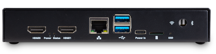
Compute Module 5 IO Board

The Compute Module 5 IO Board (CM5IO) provides the following:
-
Power and control connectors.
-
USB-C power using the same standard as Raspberry Pi 5: 5 V at 5 A (25 W) or 5 V at 3 A (15 W) with a 600 mA peripheral limit.
-
A power button for CM5.
-
Real-time clock (RTC) battery socket.
-
-
Video and display connectors.
-
Two HDMI connectors.
-
Two MIPI DSI/CSI-2 combined display/camera FPC connectors (22-pin, 0.5 mm pitch cable).
-
-
Networking and connectivity connectors.
-
Two USB 3.0 (Type-A) connectors for keyboards, storage, or peripherals.
-
A USB 2.0 (Type-C) connector for flashing CM5 or additional peripherals.
-
A Gigabit Ethernet RJ45 with PoE support.
-
-
Expansion and storage options.
-
A M.2 M key PCIe socket compatible with the 2230, 2242, 2260, and 2280 form factors.
-
A microSD card slot (only for use with CM5Lite, which has no eMMC; other variants ignore the slot).
-
HAT footprint with 40-pin GPIO connector.
-
PoE header.
-
-
Configuration options.
-
Jumpers to disable features such as eMMC boot, EEPROM write, and wireless connectivity.
-
Selectable 1.8 V or 3.3 V GPIO voltage.
-
-
Fan connector. A four-pin JST-SH PWM fan connector.
Compute Module 4 IO Board

The Compute Module 4 IO Board (CM4IO) provides the following:
-
Power and control connectors.
-
5 V through the GPIO header or 12 V input through barrel jack; supports up to 26 V if PCIe is unused.
-
Real-time clock (RTC) battery socket.
-
-
Video and display connectors.
-
Two HDMI connectors.
-
Two MIPI DSI display FPC connectors (22-pin, 0.5 mm pitch cable).
-
Two MIPI CSI-2 camera FPC connectors (22-pin, 0.5 mm pitch cable).
-
-
Networking and connectivity connectors.
-
Two USB 2.0 connectors.
-
A micro USB upstream port.
-
A Gigabit Ethernet RJ45 with PoE support.
-
-
Expansion and storage options.
-
PCIe Gen 2 socket.
-
A microSD card slot (only for use with CM4Lite, which has no eMMC; other variants ignore the slot).
-
HAT footprint with 40-pin GPIO connector.
-
PoE header.
-
-
Configuration options.
-
Jumpers to disable features such as eMMC boot, EEPROM write, and wireless connectivity.
-
Selectable 1.8 V or 3.3 V GPIO voltage.
-
-
Fan connector. Fan connector supporting standard 12 V fans with PWM drive.
Compute Module IO Board (versions 1 and 3)

There are two variants of the Compute Module IO Board:
The Compute Module IO Board (CMIO and CMIO3) provides the following:
-
Power and control connectors. 5 V input through GPIO or a micro USB connector.
-
Video and display connectors.
-
One Full size Type A HDMI.
-
Two MIPI DSI display FPC connectors (22-pin, 0.5 mm pitch cable).
-
Two MIPI CSI-2 camera FPC connectors (22-pin, 0.5 mm pitch cable).
-
-
Networking and connectivity connectors. One USB 2.0 Type-A connector.
-
Expansion and storage options.
-
46 GPIO pins.
-
(CMIO3 only) A microSD card slot (only for use with CM3Lite, CM3+Lite and CM4SLite, which have no eMMC).
-
CM5 and CM5IO accessories
Raspberry Pi offers the following accessories for CM5 and CM5IO:
-
CM5IO Case, an enclosure for a CM5IO (and attached CM5). The case also optionally fits an antenna and cooler.
-
Antenna (CM4 and CM5), a 2.4 GHz and 5 GHz antenna for wireless connectivity through CM4 or CM5.
-
CM5 Cooler, a passive heat sink to dissipate heat from CM5.
CM5IO Case
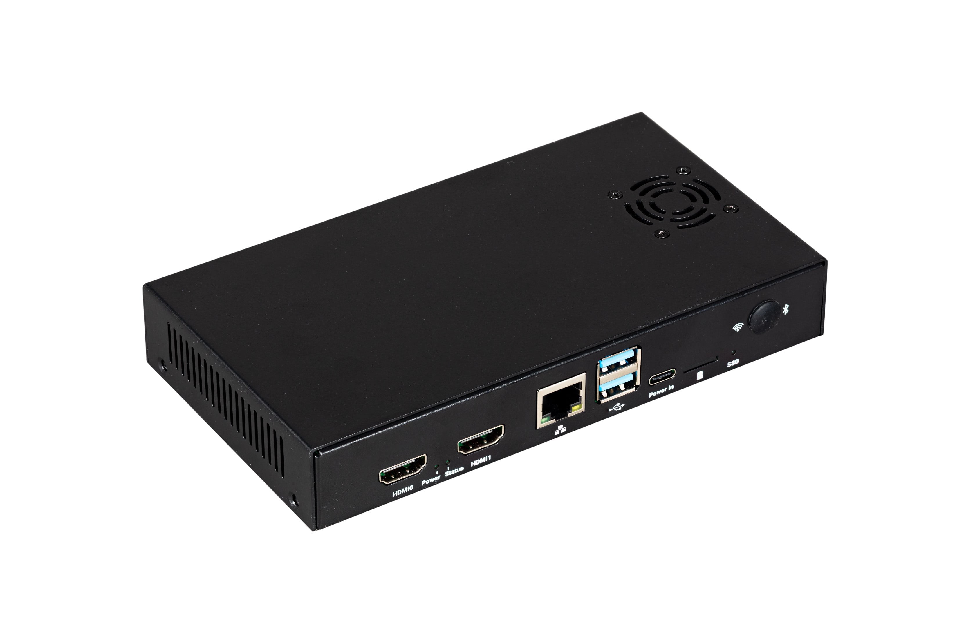
The Compute Module 5 IO Board (CM5IO) Case is a two-piece metal enclosure that, when assembled, provides physical protection for CM5IO with an attached CM5.
The following features apply to the most recent iteration of the CM5IO Case (version 2):
-
Cut-outs for externally facing connectors and LEDs.
-
A pre-installed, controllable fan that you can remove.
-
An attachment point for a Raspberry Pi Antenna Kit.
-
Space for a CM5 Cooler alongside the pre-installed fan.
-
Space for accessories connected to the IO board, such as an M.2 SSD or PoE+ HAT+.
The original version of the case doesn’t provide the internal space for all the listed items simultaneously. For more information about the different versions, see Case versions.
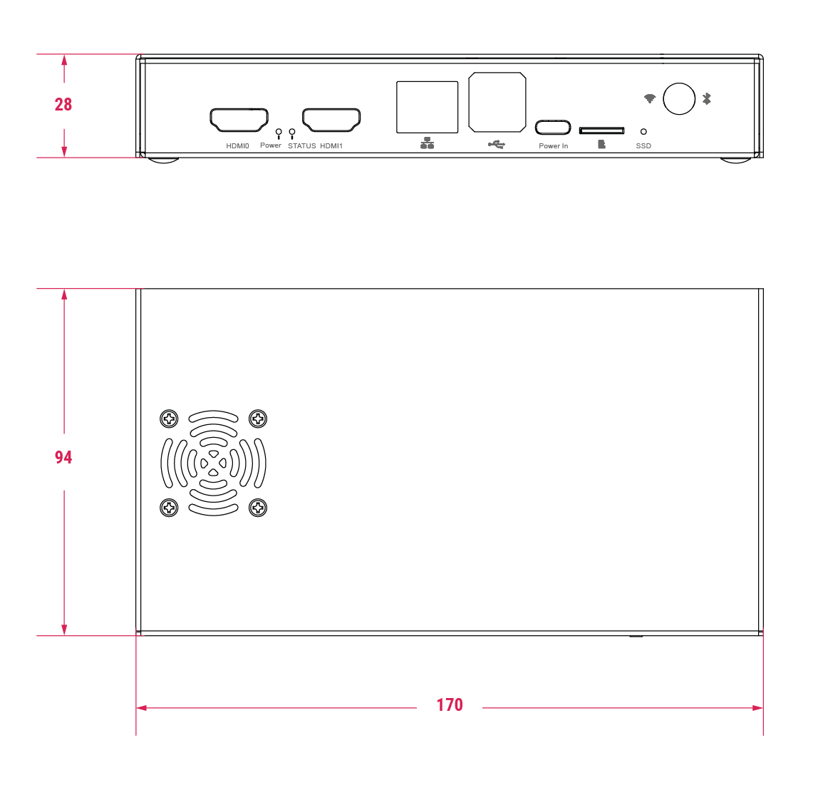
Case specifications
When assembled, the CM5IO Case measures approximately 170 mm × 94 mm × 28 mm. It’s made of sheet metal and weighs approximately 350 g.
For thermal management, the case includes a pre-installed fan that directs airflow over your CM5 and CM5IO components. You can remove or replace the fan depending on your cooling requirements. Depending on the case version, you can also optionally add a CM5 Cooler for improved thermal performance; the original case requires removing the fan first, while the updated version provides space for both the fan and cooler together.
The following image depicts the physical dimensions of the CM5IO case in millimetres (mm). The size of the case is the same for both versions; the only difference is the placement of the fan. For information about the different versions, see Case versions.
Case versions
The are two iterations of the CM5IO case, differing in the placement of the pre-installed fan: version 1 and version 2.
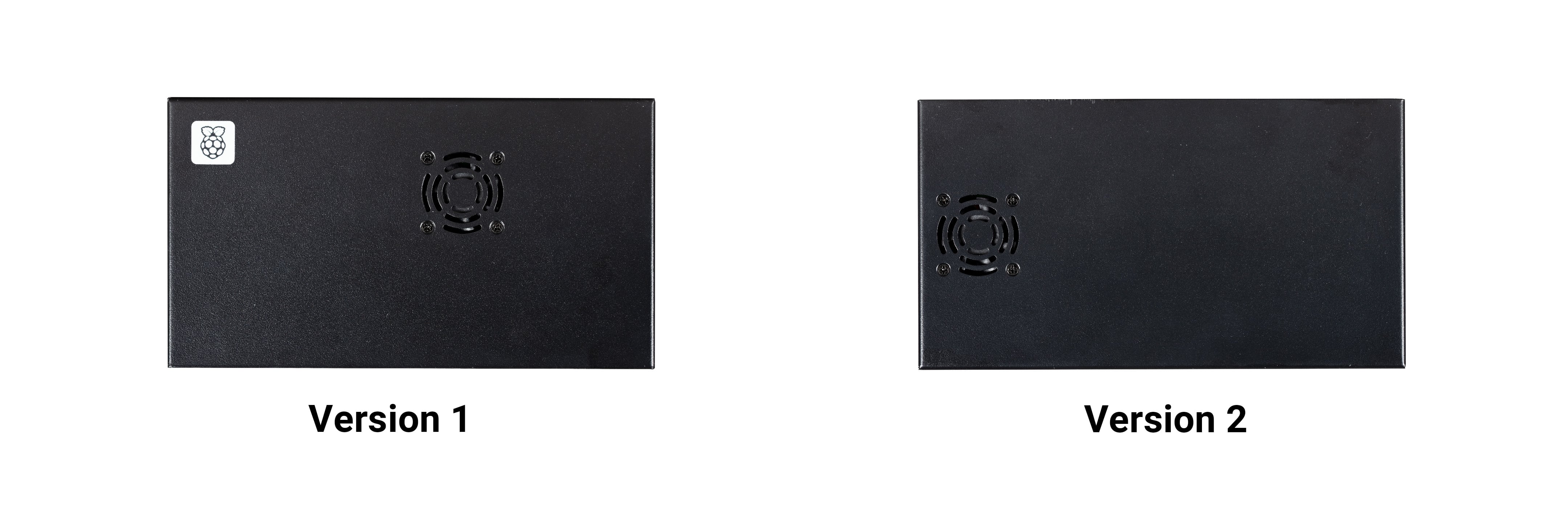
The first version features a fan that’s closer to the long edge of the enclosure. The internal layout and available clearance in this version doesn’t allow for both the fan and the CM5 Cooler to be installed inside the case at the same time. If you want to install the CM5 Cooler into the case, you must remove the fan.
The second version updates the internal layout such that the fan sits closer to the short edge of the enclosure. This revised layout provides sufficient space for both the fan and the CM5 Cooler without modification.
For instructions on mounting a CM5 Cooler onto CM5, which you can then attach to an IO board and install into the CM5IO Case, see Mount a CM5 Cooler.
Case assembly
The following steps provide instructions for assembling the most recent version of the CM5IO Case (version 2). Version 1 doesn’t allow space for both the fan and a CM5 Cooler at the same time without modification. If you have version 1 of the CM5IO Case, you can either remove the fan (described in step 4) or skip step 6 in the following instructions. For information about the different versions, see Case versions.
To mount a CM5IO inside your case:
-
Attach your CM5 to your CM5IO. Rotate your CM5 90 degrees to the right to align the dual 100-pin connectors on your CM5 with those on your CM5IO and press gently but firmly to attach them. The mounting holes should also align.
-
Open the case. Unscrew and remove the four screws (two on the left side of the case and two on the right side of the case) using a Phillips screwdriver. Then, separate the top of the case from the base. Keep the screws in a safe place.
-
Install your CM5IO assembly into the case. Place your CM5IO (with CM5 attached) into the base of the case, aligning it with the four mounting holes near the corners of the board. Ensure all externally facing connectors align with the corresponding cut-outs at the front of the case. Then, secure your CM5IO assembly to the base by screwing four M2.5 screws into the four mounting holes.
-
Connect or remove the fan.
-
If using the pre-installed fan, plug the fan connector into the four-pin fan socket labelled FAN (J14) on your CM5IO.
-
If you want to remove the fan, unscrew the four corner screws of the fan from the underside of the top of the case.
-
-
Optionally, attach an external antenna. If you want to install an antenna, follow the instructions in Connect an antenna through the CM5IO Case.
-
Optionally, attach a cooler. If you want to install a cooler, follow the instructions in Mount a CM5 Cooler. If you’re also attaching an antenna, attach the antenna’s U.FL connector first for easier access.
-
Optionally, attach a camera or display. If you’re using a camera or a display, pass the flat cable through one of the slots at the back of the case and connect it to one of the CAM/DISP ports on your CM5IO.
-
Optionally, install an M.2 SSD. If you want to install an M.2 SSD, insert it into the M.2 slot in the bottom-right corner of the CM5IO and secure it on the opposite end with a mounting screw.
-
Optionally, install a HAT. If you want to install a HAT, align it with the 40-pin GPIO header and the mounting posts such that the HAT covers the battery slot, then press it firmly into place and secure it with screws.
-
Close the case. Fold the top of the case back onto the base of the case, aligning the screw holes on the left and right sides of the case, and the power button on the back of the case. Screw the four screws back into place using a Phillips screwdriver, taking care not to overtighten them.
|
Note
|
The SD card slot is a push-push slot. To insert an SD card, push it into the SD card slot with the contacts facing downwards. To remove it, push it inwards towards the slot to release it and then pull it out. |
Antenna (CM4 and CM5)
The Raspberry Pi Antenna Kit provides a certified external antenna to boost wireless reception on a CM4 or CM5.

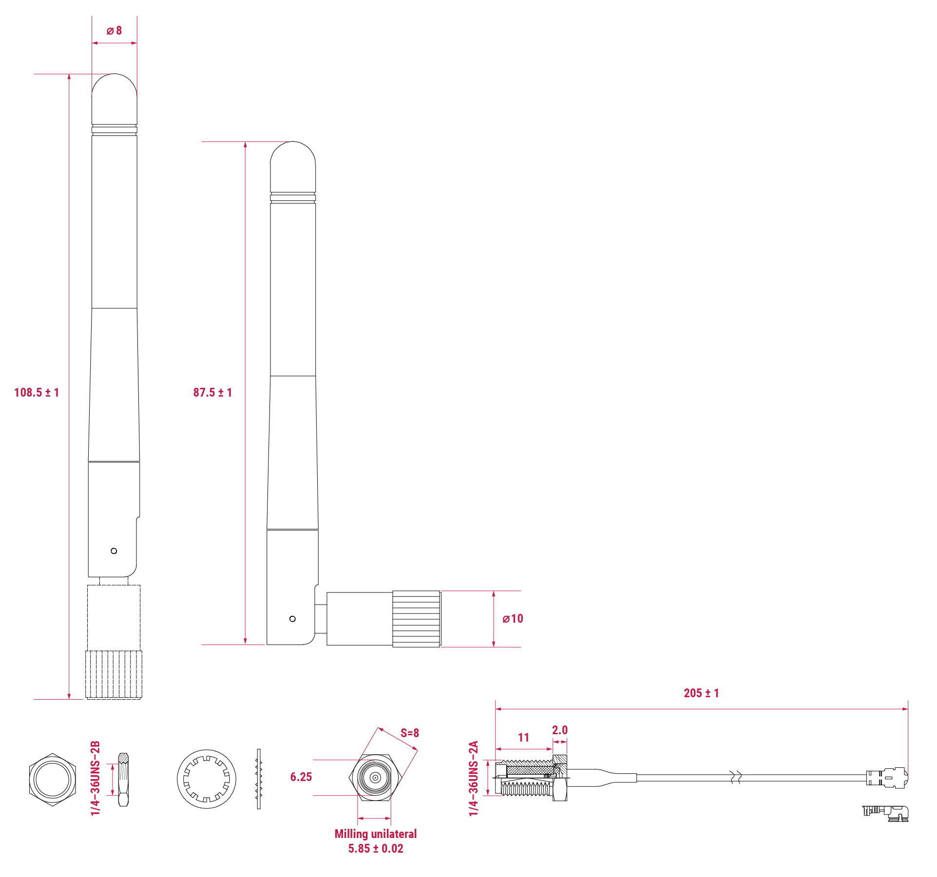
Antenna specifications
The antenna supports dual-band Wi-Fi and attaches to the U.FL connector on your CM4 or CM5. The antenna is approximately 108.5 mm at full height and approximately 87.5 mm long when at a 90 degree angle; the SMA to U.FL cable is approximately 205 mm long.
Connect an antenna through the CM5IO Case
You can use the antenna with the CM5IO Case. To attach the antenna to your Compute Module through the CM5IO Case, complete the first four steps outlined in Case assembly, and then complete following steps:
-
Connect the U.FL connector. Connect the U.FL connector on the antenna cable to the U.FL-compatible connector on your Compute Module, next to the top-left mounting hole of your CM5. Do this before attaching a cooler (if using one) because the cooler can make it harder to attach the U.FL connector.
-
Insert the SMA connector. Remove the rubber plug from the antenna port on the inside of the CM5IO Case. Then, from the inside of the case, push the SMA connector with the (flat side up) into the antenna port so that it extends through and is accessible from the outside.
-
Fasten the SMA connector into place. Twist the retaining hexagonal nut and washer onto the SMA connector in a clockwise direction until it sits securely in place. Avoid excessive twisting when tightening to prevent damage.
-
Attach the antenna to the SMA connector. Insert the SMA connector into the antenna port with the antenna facing outward and twist the antenna clockwise to secure it.
-
Adjust the antenna. Move the antenna into its final position by turning it up to a 90 degree angle.
You can now complete the remaining steps outlined in Case assembly for mounting a CM5IO inside your case.

To use the Antenna with your Compute Module, add a dtparam instruction in /boot/firmware/config.txt. Add the following line to the end of the config.txt file: dtparam=ant2
CM5 Cooler
The CM5 Cooler is a passive heat sink that helps dissipate heat from your CM5, improving CPU performance and longevity.

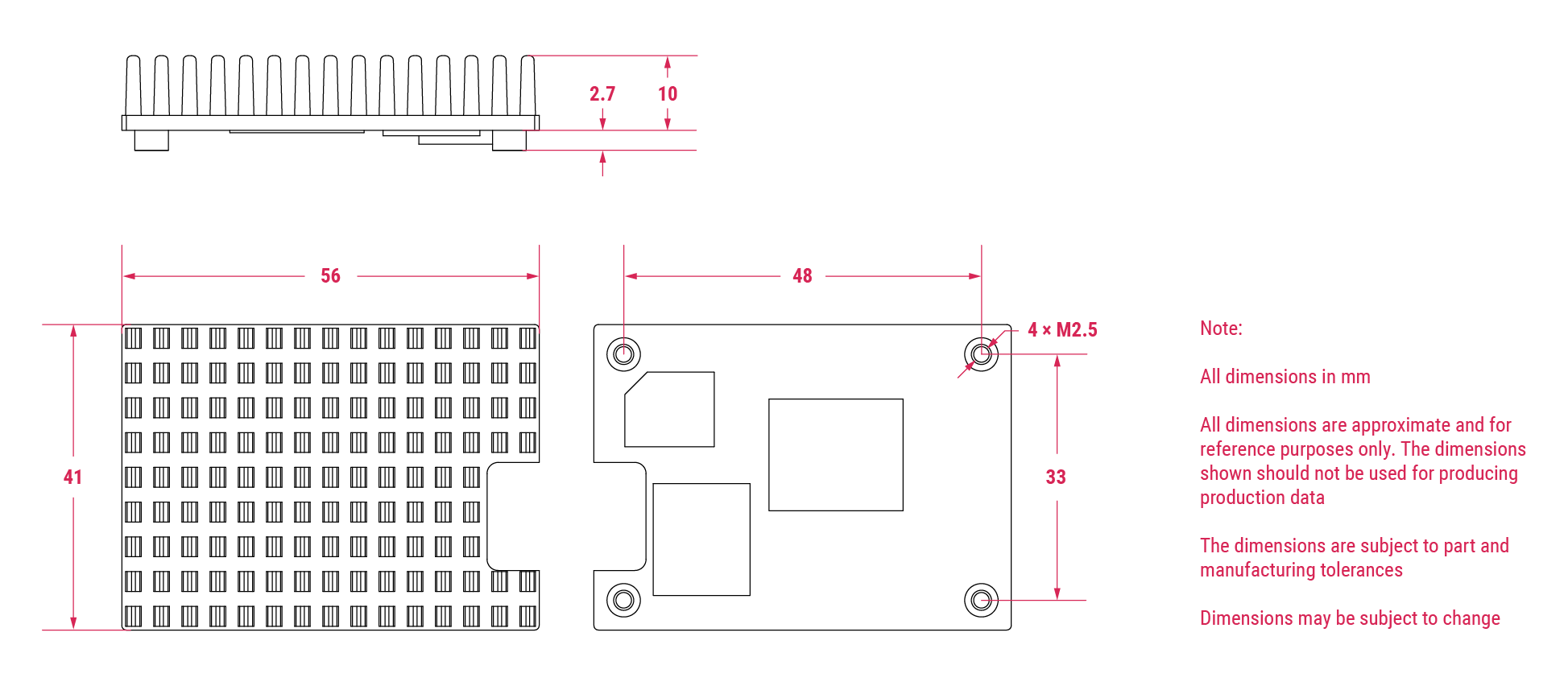
Cooler specifications
The CM5 Cooler dimensions are approximately 41 mm × 56 mm × 12.7 mm. The cooler is an aluminium heat sink with a conductive silicone pad on the bottom. Newer versions of the CM5IO Case allow both the cooler and pre-installed fan to be used inside the case at the same time. If you have an older version of the CM5IO Case, you must remove the fan from the case to allow space for the cooler.
Mount a CM5 Cooler
To mount the cooler to your CM5:
-
Remove the protective paper from the silicone pad on the bottom of cooler.
-
Attach the silicone at the bottom of the cooler to the top of your CM5. Place the cooler on your CM5 such that the cutout in the cooler is above the on-board antenna (the trapezoid-shaped area on the left of a CM5) and the U.FL connector next to it (if it has one).
-
Optionally, fasten screws in the mounting points found in each corner to secure the cooler. If you omit the screws, the bond between your cooler and your CM5 improves through time and use.
Flash an image to a Compute Module
Edit this on GitHub
|
Tip
|
To flash the same image to multiple Compute Modules, use the Raspberry Pi Secure Boot Provisioner. To customise an OS image to flash onto those devices, use pi-gen. |
The Compute Module has an on-board eMMC device connected to the primary SD card interface. This guide explains how to flash (write) an operating system image to the eMMC storage of a single Compute Module.
Lite variants of Compute Modules do not have on-board eMMC. Instead, follow the procedure to flash a storage device for other Raspberry Pi devices at Install an operating system.
Prerequisites
To flash the Compute Module eMMC, you need the following:
-
Another computer, referred to in this guide as the host device. You can use Linux (we recommend Raspberry Pi OS or Ubuntu), Windows 11, or macOS.
-
The Compute Module IO Board that corresponds to your Compute Module model.
-
A micro USB cable, or a USB-C cable for Compute Module models since CM5IO.
|
Tip
|
In some cases, USB hubs can prevent the host device from recognising the Compute Module. If your host device doesn’t recognise the Compute Module, try connecting the Compute Module directly to the host device. For more diagnostic tips, see the usbboot troubleshooting guide. |
Set up the IO Board
To begin, physically set up your IO Board. This includes connecting the Compute Module and host device to the IO Board.
-
Compute Module 5 IO Board
-
Compute Module 4 IO Board
-
Compute Module IO Board
To set up the Compute Module 5 IO Board:
-
Connect the Compute Module to the IO board. When connected, the Compute Module should lie flat.
-
Fit
nRPI_BOOTto J2 (disable eMMC Boot) on the IO board jumper. -
Connect a cable from USB-C slave port J11 on the IO board to the host device.
To set up the Compute Module 4 IO Board:
-
Connect the Compute Module to the IO board. When connected, the Compute Module should lie flat.
-
Fit
nRPI_BOOTto J2 (disable eMMC Boot) on the IO board jumper. -
Connect a cable from micro USB slave port J11 on the IO board to the host device.
To set up the Compute Module IO Board:
-
Connect the Compute Module to the IO board. When connected, the Compute Module should lie parallel to the board, with the engagement clips firmly clicked into place.
-
Set J4 (
USB SLAVE BOOT ENABLE) to 1-2 = (USB BOOT ENABLED) -
Connect a cable from micro USB slave port J15 on the IO board to the host device.
Set up the host device
Next, let’s set up software on the host device.
|
Tip
|
For a host device, we recommend a Raspberry Pi 4 or newer running 64-bit Raspberry Pi OS. |
-
Linux
-
macOS
-
Windows
To set up software on a Linux host device:
-
Run the following command to install
rpiboot(or, alternatively, buildrpibootfrom source):$ sudo apt install rpiboot -
Connect the IO Board to power.
-
Then, run
rpiboot:$ sudo rpiboot -
After a few seconds, the Compute Module should appear as a mass storage device. Check the
/dev/directory, likely/dev/sdaor/dev/sdb, for the device. Alternatively, runlsblkand search for a device with a storage capacity that matches the capacity of your Compute Module.
To set up software on a macOS host device:
-
First, build
rpibootfrom source. -
Connect the IO Board to power.
-
Then, run the
rpibootexecutable with the following command:$ rpiboot -d mass-storage-gadget64 -
When the command finishes running, you should see a message stating "The disk you inserted was not readable by this computer." Click Ignore. Your Compute Module should now appear as a mass storage device.
To set up software on a Windows 11 host device:
-
Download the latest Windows installer from the releases page or build
rpibootfrom source. -
Double-click on the installer to run it. This installs the drivers and boot tool. Do not close any driver installation windows which appear during the installation process.
-
Reboot
-
Connect the IO Board to power. Windows should discover the hardware and configure the required drivers.
-
Select rpiboot - Mass Storage Gadget from the start menu. After a few seconds, the Compute Module eMMC, NVMe or SD card appears as a USB mass storage device. This also provides a debug console as a serial port gadget.
Flash the eMMC
You can use Raspberry Pi Imager to flash an operating system image to a Compute Module.
Alternatively, use dd to write a raw OS image (such as Raspberry Pi OS) to your Compute Module. Run the following command, replacing /dev/sdX with the path to the mass storage device representation of your Compute Module and raw_os_image.img with the path to your raw OS image:
$ sudo dd if=raw_os_image.img of=/dev/sdX bs=4MiBAfter the image has been written, disconnect and reconnect the Compute Module. You now see two partitions (for Raspberry Pi OS):
/dev/sdX    <- Device
/dev/sdX1   <- First partition (FAT)
/dev/sdX2   <- Second partition (Linux filesystem)
You can mount the /dev/sdX1 and /dev/sdX2 partitions normally.
Boot from eMMC
-
Compute Module 5 IO Board
-
Compute Module 4 IO Board
-
Compute Module IO Board
Disconnect nRPI_BOOT from J2 (disable eMMC Boot) on the IO board jumper.
Disconnect nRPI_BOOT from J2 (disable eMMC Boot) on the IO board jumper.
Set J4 (USB SLAVE BOOT ENABLE) to 2-3 (USB BOOT DISABLED).
Known issues
-
A small percentage of CM3 devices may experience problems booting. We have traced these back to the method used to create the FAT32 partition; we believe the problem is due to a difference in timing between the CPU and eMMC. If you have trouble booting your CM3, create the partitions manually with the following commands:
$ sudo parted /dev/<device> (parted) mkpart primary fat32 4MiB 64MiB (parted) q $ sudo mkfs.vfat -F32 /dev/<device> $ sudo cp -r <files>/* <mountpoint> -
The CM1 bootloader returns a slightly incorrect USB packet to the host. Most USB hosts ignore it, but some USB ports don’t work due to this bug. CM3 fixed this bug.
-
The rpiboot version distributed with Ubuntu 24.04 and earlier has been known to fail to communicate with the device. To resolve this issue, build
rpibootfrom source.
Compute Module EEPROM bootloader
Edit this on GitHub
Since Compute Module 4, Compute Modules use an EEPROM bootloader. This bootloader lives in a small segment of on-board storage instead of the boot partition. As a result, it requires different procedures to update. Before using a Compute Module with an EEPROM bootloader in production, always follow these best practices:
-
Select a specific bootloader release. Verify that every Compute Module you use has that release. The version in the
usbbootrepo is always a recent stable release. -
Configure the boot device by setting the
BOOT_ORDER. -
Enable hardware write-protection on the bootloader EEPROM to ensure that the bootloader can’t be modified on inaccessible products (such as remote or embedded devices).
Flash Compute Module bootloader EEPROM
To flash the bootloader EEPROM:
-
Set up the hardware as you would when flashing the eMMC, but ensure
EEPROM_nWPis not pulled low. -
Run the following command to write
recovery/pieeprom.binto the bootloader EEPROM:$ ./rpiboot -d recovery -
When complete,
EEPROM_nWPmay be pulled low again.
Flash storage devices other than SD cards
The Linux-based mass-storage-gadget supports flashing of NVMe, eMMC, and USB block devices. mass-storage-gadget writes devices faster than the firmware-based rpiboot mechanism, and also provides a UART console to the device for debugging.
usbboot also includes a number of extensions that enable you to provision secure-boot or launch custom Linux initramfs images.
Update the Compute Module bootloader
On Compute Modules with an EEPROM bootloader, ROM never runs recovery.bin from SD/eMMC. These Compute Modules disable the rpi-eeprom-update service by default, because eMMC is not removable and an invalid recovery.bin file could prevent the system from booting.
You can override this behaviour with self-update mode. In self-update mode, you can update the bootloader from USB MSD or network boot.
|
Warning
|
self-update mode does not update the bootloader atomically. If a power failure occurs during an EEPROM update, you could corrupt the EEPROM.
|
Modify the bootloader configuration
To modify the Compute Module EEPROM bootloader configuration:
-
Navigate to the
usbboot/recoverydirectory. -
If you require a specific bootloader release, replace
pieeprom.original.binwith the equivalent from your bootloader release. -
Edit the default
boot.confbootloader configuration file to define aBOOT_ORDER:-
For network boot, use
BOOT_ORDER=0xf2. -
For SD/eMMC boot, use
BOOT_ORDER=0xf1. -
For USB boot failing over to eMMC, use
BOOT_ORDER=0xf15. -
For NVMe boot, use
BOOT_ORDER=0xf6.
-
-
Run
./update-pieeprom.shto generate a new EEPROM imagepieeprom.binimage file. -
If you require EEPROM write-protection, add
eeprom_write_protect=1to/boot/firmware/config.txt.-
When enabled in software, you can lock hardware write-protection by pulling the
EEPROM_nWPpin low.
-
-
Run the following command to write the updated
pieeprom.binimage to EEPROM:$ ../rpiboot -d .
Wire peripherals
Edit this on GitHub
This guide helps developers wire up peripherals to the Compute Module pins, and explains how to enable these peripherals in software.
Most of the pins of the SoC, including the GPIO, two CSI camera interfaces, two DSI display interfaces, and HDMI are available for wiring. You can can usually leave unused pins disconnected.
Compute Modules that come in the DDR2 SODIMM form factor are physically compatible with any DDR2 SODIMM socket. However, the pinout is not the same as SODIMM memory modules.
To use a Compute Module, a user must design a motherboard that:
-
provides power to the Compute Module (3.3V and 1.8V at minimum)
-
connects the pins to the required peripherals for the user’s application
This guide first explains the boot process and how Device Tree describes attached hardware.
Then, we’ll explain how to attach an I2C and an SPI peripheral to an IO Board. Finally, we’ll create the Device Tree files necessary to use both peripherals with Raspberry Pi OS.
BCM283x GPIOs
BCM283x has three banks of general-purpose input/output (GPIO) pins: 28 pins on Bank 0, 18 pins on Bank 1, and 8 pins on Bank 2, for a total of 54 pins. These pins can be used as true GPIO pins: software can set them as inputs or outputs, read and/or set state, and use them as interrupts. They also can run alternate functions such as I2C, SPI, I2S, UART, SD card, and others.
You can use Bank 0 or Bank 1 on any Compute Module. Don’t use Bank 2: it controls eMMC, HDMI hot plug detect, and ACT LED/USB boot control.
Use pinctrl to check the voltage and function of the GPIO pins to see if your Device Tree is working as expected.
BCM283x boot process
BCM283x devices have a VideoCore GPU and Arm CPU cores. The GPU consists of a DSP processor and hardware accelerators for imaging, video encode and decode, 3D graphics, and image compositing.
In BCM283x devices, the DSP core in the GPU boots first. It handles setup before booting up the main Arm processors.
Raspberry Pi BCM283x devices have a three-stage boot process:
-
The GPU DSP comes out of reset and executes code from the small internal boot ROM. This code loads a second-stage bootloader via an external interface. This code first looks for a second-stage boot loader on the boot device called
bootcode.binon the boot partition. If no boot device is found orbootcode.binis not found, the boot ROM waits in USB boot mode for a host to provide a second-stage boot loader (usbbootcode.bin). -
The second-stage boot loader is responsible for setting up the LPDDR2 SDRAM interface and other critical system functions. When set up, the second-stage boot loader loads and executes the main GPU firmware (
start.elf). -
start.elfhandles additional system setup and boots up the Arm processor subsystem. It contains the GPU firmware. The GPU firmware first readsdt-blob.binto determine initial GPIO pin states and GPU-specific interfaces and clocks, then parsesconfig.txt. It then loads a model-specific Arm device tree file and any Device Tree overlays specified inconfig.txtbefore starting the Arm subsystem and passing the Device Tree data to the booting Linux kernel.
Device Tree
Linux Device Tree for Raspberry Pi encodes information about hardware attached to a system as well as the drivers used to communicate with that hardware.
The boot partition contains several binary Device Tree (.dtb) files. The Device Tree compiler creates these binary files using human-readable Device Tree descriptions (.dts).
The boot partition contains two different types of Device Tree files. One is used by the GPU only; the rest are standard Arm Device Tree files for each of the BCM283x-based Raspberry Pi products:
-
dt-blob.bin(used by the GPU) -
bcm2708-rpi-b.dtb(Used for Raspberry Pi 1 Models A and B) -
bcm2708-rpi-b-plus.dtb(Used for Raspberry Pi 1 Models B+ and A+) -
bcm2709-rpi-2-b.dtb(Used for Raspberry Pi 2 Model B) -
bcm2710-rpi-3-b.dtb(Used for Raspberry Pi 3 Model B) -
bcm2708-rpi-cm.dtb(Used for Raspberry Pi Compute Module 1) -
bcm2710-rpi-cm3.dtb(Used for Raspberry Pi Compute Module 3)
During boot, the user can specify a specific Arm Device Tree to use via the device_tree parameter in config.txt. For example, the line device_tree=mydt.dtb in config.txt specifies an Arm Device Tree in a file named mydt.dtb.
You can create a full Device Tree for a Compute Module product, but we recommend using overlays instead. Overlays add descriptions of non-board-specific hardware to the base Device Tree. This includes GPIO pins used and their function, as well as the devices attached, so that the correct drivers can be loaded. The bootloader merges overlays with the base Device Tree before passing the Device Tree to the Linux kernel. Occasionally the base Device Tree changes, usually in a way that will not break overlays.
Use the dtoverlay parameter in config.txt to load Device Tree overlays. Raspberry Pi OS assumes that all overlays are located in the /overlays directory and use the suffix -overlay.dtb. For example, the line dtoverlay=myoverlay loads the overlay /overlays/myoverlay-overlay.dtb.
To wire peripherals to a Compute Module, describe all hardware attached to the Bank 0 and Bank 1 GPIOs in an overlay. This allows you to use standard Raspberry Pi OS images, since the overlay is merged into the standard base Device Tree. Alternatively, you can define a custom Device Tree for your application, but you won’t be able to use standard Raspberry Pi OS images. Instead, you must create a modified Raspberry Pi OS image that includes your custom device tree for every OS update you wish to distribute. If the base overlay changes, you might need to update your customised Device Tree.
dt-blob.bin
When start.elf runs, it first reads dt-blob.bin. This is a special form of Device Tree blob which tells the GPU how to set up the GPIO pin states.
dt-blob.bin contains information about GPIOs and peripherals controlled by the GPU, instead of the SoC. For example, the GPU manages Camera Modules. The GPU needs exclusive access to an I2C interface and a couple of pins to talk to a Camera Module.
On most Raspberry Pi models, I2C0 is reserved for exclusive GPU use. dt-blob.bin defines the GPIO pins used for I2C0.
By default, dt-blob.bin does not exist. Instead, start.elf includes a built-in version of the file. Many Compute Module projects provide a custom dt-blob.bin which overrides the default built-in file.
dt-blob.bin specifies:
-
the pin used for HDMI hot plug detect
-
GPIO pins used as a GPCLK output
-
an ACT LED that the GPU can use while booting
minimal-cm-dt-blob.dts is an example .dts device tree file. It sets up HDMI hot plug detection, an ACT LED, and sets all other GPIOs as inputs with default pulls.
To compile minimal-cm-dt-blob.dts to dt-blob.bin, use the Device Tree compiler dtc.
To install dtc on a Raspberry Pi, run the following command:
$ sudo apt install device-tree-compilerThen, run the follow command to compile minimal-cm-dt-blob.dts into dt-blob.bin:
$ dtc -I dts -O dtb -o dt-blob.bin minimal-cm-dt-blob.dtsFor more information, see our guide to creating dt-blob.bin.
Arm Linux Device Tree
After start.elf reads dt-blob.bin and sets up the initial pin states and clocks, it reads config.txt, which contains many other options for system setup.
After reading config.txt, start.elf reads a model-specific Device Tree file. For instance, Compute Module 3 uses bcm2710-rpi-cm.dtb. This file is a standard Arm Linux Device Tree file that details hardware attached to the processor. It enumerates:
-
what and where peripheral devices exist
-
which GPIOs are used
-
what functions those GPIOs have
-
what physical devices are connected
This file sets up the GPIOs by overwriting the pin state in dt-blob.bin if it is different. It will also try to load drivers for the specific devices.
The model-specific Device Tree file contains disabled entries for peripherals. It contains no GPIO pin definitions other than the eMMC/SD Card peripheral which has GPIO defs and always uses the same pins.
Device Tree source and compilation
The Raspberry Pi OS image provides compiled dtb files, but the source dts files live in the Raspberry Pi Linux kernel branch. Look for rpi in the file names.
Default overlay dts files live at arch/arm/boot/dts/overlays. These overlay files are a good starting point for creating your own overlays. To compile these dts files to dtb files, use the Device Tree compiler dtc.
When building your own kernel, the build host requires the Device Tree compiler in scripts/dtc. To build your overlays automatically, add them to the dtbs make target in arch/arm/boot/dts/overlays/Makefile.
Device Tree debugging
When booting the Linux kernel, the GPU provides a fully assembled Device Tree created using the base dts and any overlays. This full tree is available via the Linux proc interface in /proc/device-tree. Nodes become directories and properties become files.
You can use dtc to write this out as a human readable dts file for debugging. To see the fully assembled device tree, run the following command:
$ dtc -I fs -O dts -o proc-dt.dts /proc/device-treepinctrl provides the status of the GPIO pins. If something seems to be going awry, try dumping the GPU log messages:
$ sudo vclog --msg|
Tip
|
To include even more diagnostics in the output, add dtdebug=1 to config.txt.
|
Use the Device Tree Raspberry Pi forum to ask Device Tree-related questions or report an issue.
Examples
The following examples use an IO Board with peripherals attached via jumper wires. We assume a CM1+CMIO or CM3+CMIO3, running a clean install of Raspberry Pi OS Lite. The examples here require internet connectivity, so we recommend a USB hub, keyboard, and wireless LAN or Ethernet dongle plugged into the IO Board USB port.
Attach an I2C RTC to Bank 1 pins
In this example, we wire an NXP PCF8523 real time clock (RTC) to the IO Board Bank 1 GPIO pins: 3V3, GND, I2C1_SDA on GPIO44 and I2C1_SCL on GPIO45.
Download minimal-cm-dt-blob.dts and copy it to the boot partition in /boot/firmware/.
Edit minimal-cm-dt-blob.dts and change the pin states of GPIO44 and 45 to be I2C1 with pull-ups:
$ sudo nano /boot/firmware/minimal-cm-dt-blob.dtsReplace the following lines:
pin@p44 { function = "input"; termination = "pull_down"; }; // DEFAULT STATE WAS INPUT NO PULL
pin@p45 { function = "input"; termination = "pull_down"; }; // DEFAULT STATE WAS INPUT NO PULL
With the following pull-up definitions:
pin@p44 { function = "i2c1"; termination = "pull_up"; }; // SDA1
pin@p45 { function = "i2c1"; termination = "pull_up"; }; // SCL1
We could use this dt-blob.dts with no changes, because the Linux Device Tree re-configures these pins during Linux kernel boot when the specific drivers load. However, if you configure dt-blob.dts, the GPIOs reach their final state as soon as possible during the GPU boot stage. In some cases, pins must be configured at GPU boot time so they are in a specific state when Linux drivers are loaded. For example, a reset line may need to be held in the correct orientation.
Run the following command to compile dt-blob.bin:
$ sudo dtc -I dts -O dtb -o /boot/firmware/dt-blob.bin /boot/firmware/minimal-cm-dt-blob.dtsDownload example1-overlay.dts, copy it to the boot partition in /boot/firmware/, then compile it with the following command:
$ sudo dtc -@ -I dts -O dtb -o /boot/firmware/overlays/example1.dtbo /boot/firmware/example1-overlay.dtsThe -@ flag compiles dts files with external references. It is usually necessary.
Add the following line to /boot/firmware/config.txt:
dtoverlay=example1Finally, reboot with sudo reboot.
After reboot, you see an rtc0 entry in /dev. Run the following command to view the hardware clock time:
$ sudo hwclockAttach an ENC28J60 SPI Ethernet controller on Bank 0
In this example, we use an overlay already defined in /boot/firmware/overlays to add an ENC28J60 SPI Ethernet controller to Bank 0. The Ethernet controller uses SPI pins CE0, MISO, MOSI and SCLK (GPIO8-11 respectively), GPIO25 for a falling edge interrupt, in addition to GND and 3.3V.
In this example, we won’t change dt-blob.bin. Instead, add the following line to /boot/firmware/config.txt:
dtoverlay=enc28j60Reboot with sudo reboot.
If you now run ifconfig you should see an additional eth<n> entry for the ENC28J60 NIC. You should also have Ethernet connectivity. Run the following command to test your connectivity:
$ ping 8.8.8.8Run the following command to show GPIO functions; GPIO8-11 should now provide ALT0 (SPI) functions:
$ pinctrlAttach a Camera Module
Edit this on GitHub
The Compute Module has two CSI-2 camera interfaces: CAM1 and CAM0. This section explains how to connect one or two Raspberry Pi Cameras to a Compute Module using the CAM1 and CAM0 interfaces with a Compute Module I/O Board.
Update your system
Before configuring a camera, ensure that your Raspberry Pi firmware is up-to-date.:
$ sudo apt update
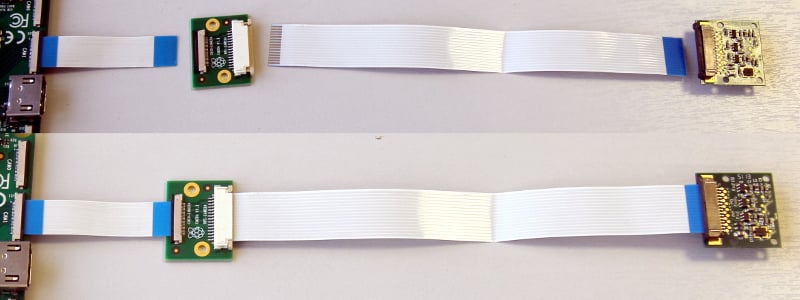
$ sudo apt full-upgradeConnect one camera
To connect a single camera to a Compute Module, complete the following steps:
-
Disconnect the Compute Module from power.
-
Connect the Camera Module to the CAM1 port using a RPI-CAMERA board or a Raspberry Pi Zero camera cable.
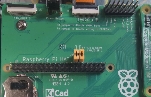
-
(CM5 only): Fit two jumpers on J6 per the board’s written instructions.
-
(CM1, CM3, CM3+, and CM4S only): Connect the following GPIO pins with jumper cables:
-
0toCD1_SDA -
1toCD1_SCL -
2toCAM1_I01 -
3toCAM1_I00
-
-
Reconnect the Compute Module to power.
-
Remove (or comment out with the prefix
#) the following lines, if they exist, in/boot/firmware/config.txt:camera_auto_detect=1dtparam=i2c_arm=on -
(CM1, CM3, CM3+, and CM4S only): Add the following directive to
/boot/firmware/config.txtto accommodate the swapped GPIO pin assignment on the I/O board:dtoverlay=cm-swap-i2c0 -
(CM1, CM3, CM3+, and CM4S only): Add the following directive to
/boot/firmware/config.txtto assign GPIO 3 as the CAM1 regulator:dtparam=cam1_reg -
Add the appropriate directive to
/boot/firmware/config.txtto manually configure the driver for your camera model:camera model directive v1 camera
dtoverlay=ov5647v2 camera
dtoverlay=imx219v3 camera
dtoverlay=imx708HQ camera
dtoverlay=imx477GS camera
dtoverlay=imx296 -
Reboot your Compute Module with
sudo reboot. -
Run the following command to check the list of detected cameras:
$ rpicam-hello --listYou should see your camera model, referred to by the driver directive in the table above, in the output.
Connect two cameras
To connect two cameras to a Compute Module, complete the following steps:
-
Follow the single camera instructions above.
-
Disconnect the Compute Module from power.
-
Connect the Camera Module to the CAM0 port using a RPI-CAMERA board or a Raspberry Pi Zero camera cable.
-
(CM1, CM3, CM3+, and CM4S only): Connect the following GPIO pins with jumper cables:
-
28toCD0_SDA -
29toCD0_SCL -
30toCAM0_I01 -
31toCAM0_I00
-
-
(CM4): Connect the J6 GPIO pins with two vertical-orientation jumpers.

-
Reconnect the Compute Module to power.
-
(CM1, CM3, CM3+, and CM4S only): Add the following directive to
/boot/firmware/config.txtto assign GPIO 31 as the CAM0 regulator:dtparam=cam0_reg -
Add the appropriate directive to
/boot/firmware/config.txtto manually configure the driver for your camera model:camera model directive v1 camera
dtoverlay=ov5647,cam0v2 camera
dtoverlay=imx219,cam0v3 camera
dtoverlay=imx708,cam0HQ camera
dtoverlay=imx477,cam0GS camera
dtoverlay=imx296,cam0 -
Reboot your Compute Module with
sudo reboot. -
Run the following command to check the list of detected cameras:
$ rpicam-hello --listYou should see both camera models, referred to by the driver directives in the table above, in the output.
Software
Raspberry Pi OS includes the libcamera library to help you take images with your Raspberry Pi.
Take a picture
Use the following command to immediately take a picture and save it to a file in PNG encoding using the MMDDhhmmss date format as a filename:
$ rpicam-still --datetime -e pngUse the -t option to add a delay in milliseconds.
Use the --width and --height options to specify a width and height for the image.
Take a video
Use the following command to immediately start recording a ten-second long video and save it to a file with the h264 codec named video.h264:
$ rpicam-vid -t 10000 -o video.h264Specify which camera to use
By default, libcamera always uses the camera with index 0 in the --list-cameras list.
To specify a camera option, get an index value for each camera from the following command:
$ rpicam-hello --list-cameras
Available cameras
-----------------
0 : imx477 [4056x3040] (/base/soc/i2c0mux/i2c@1/imx477@1a)
    Modes: 'SRGGB10_CSI2P' : 1332x990 [120.05 fps - (696, 528)/2664x1980 crop]
           'SRGGB12_CSI2P' : 2028x1080 [50.03 fps - (0, 440)/4056x2160 crop]
                             2028x1520 [40.01 fps - (0, 0)/4056x3040 crop]
                             4056x3040 [10.00 fps - (0, 0)/4056x3040 crop]

1 : imx708 [4608x2592] (/base/soc/i2c0mux/i2c@0/imx708@1a)
    Modes: 'SRGGB10_CSI2P' : 1536x864 [120.13 fps - (768, 432)/3072x1728 crop]
                             2304x1296 [56.03 fps - (0, 0)/4608x2592 crop]
                             4608x2592 [14.35 fps - (0, 0)/4608x2592 crop]
In the above output:
-
imx477refers to a HQ camera with an index of0 -
imx708refers to a v3 camera with an index of1
To use the HQ camera, pass its index (0) to the --camera libcamera option:
$ rpicam-hello --camera 0To use the v3 camera, pass its index (1) to the --camera libcamera option:
$ rpicam-hello --camera 1I2C mapping of GPIO pins
By default, the supplied camera drivers assume that CAM1 uses i2c-10 and CAM0 uses i2c-0. Compute module I/O boards map the following GPIO pins to i2c-10 and i2c-0:
| I/O Board Model |
i2c-10 pins |
i2c-0 pins |
|---|---|---|
CM4 I/O Board |
GPIOs 44,45 |
GPIOs 0,1 |
CM1, CM3, CM3+, CM4S I/O Board |
GPIOs 0,1 |
GPIOs 28,29 |
To connect a camera to the CM1, CM3, CM3+ and CM4S I/O Board, add the following directive to /boot/firmware/config.txt to accommodate the swapped pin assignment:
dtoverlay=cm-swap-i2c0Alternative boards may use other pin assignments. Check the documentation for your board and use the following alternate overrides depending on your layout:
| Swap | Override |
|---|---|
Use GPIOs 0,1 for i2c0 |
|
Use GPIOs 28,29 for i2c0 (default) |
|
Use GPIOs 44&45 for i2c0 |
|
Use GPIOs 0&1 for i2c10 (default) |
|
Use GPIOs 28&29 for i2c10 |
|
Use GPIOs 44&45 for i2c10 |
|
GPIO pins for shutdown
For camera shutdown, Device Tree uses the pins assigned by the cam1_reg and cam0_reg overlays.
The CM4 IO board provides a single GPIO pin for both aliases, so both cameras share the same regulator.
The CM1, CM3, CM3+, and CM4S I/O boards provides no GPIO pin for cam1_reg and cam0_reg, so the regulators are disabled on those boards. However, you can enable them with the following directives in /boot/firmware/config.txt:
-
dtparam=cam1_reg -
dtparam=cam0_reg
To assign cam1_reg and cam0_reg to a specific pin on a custom board, use the following directives in /boot/firmware/config.txt:
-
dtparam=cam1_reg_gpio=<pin number> -
dtparam=cam0_reg_gpio=<pin number>
For example, to use pin 42 as the regulator for CAM1, add the directive dtparam=cam1_reg_gpio=42 to /boot/firmware/config.txt.
These directives only work for GPIO pins connected directly to the SoC, not for expander GPIO pins.
Attach a Touch Display LCD panel
Edit this on GitHub
-
To connect to a Raspberry Pi Touch Display, see Touch Display.
-
To connect to a Raspberry Pi Touch Display 2, see Touch Display 2.
Specifications
Edit this on GitHub
Compute Module 5 datasheet
To learn more about Compute Module 5 (CM5) and its corresponding IO Board, see the following documents:
Compute Module 5 IO Board datasheet
Design data for the Compute Module 5 IO Board (CM5IO) can be found in its datasheet:
Compute Module 4 datasheet
To learn more about Compute Module 4 (CM4) and its corresponding IO Board, see the following documents:
Compute Module 4 IO Board datasheet
Design data for the Compute Module 4 IO Board (CM4IO) can be found in its datasheet:
We also provide a KiCad PCB design set for the CM4 IO Board:
Compute Module 4S datasheet
Compute Module 4S (CM4S) offers the internals of CM4 in the DDR2-SODIMM form factor of CM1, CM3, and CM3+. To learn more about CM4S, see the following documents:
Compute Module 3+ datasheet
Compute Module 3+ (CM3+) is a supported product with an end-of-life (EOL) date no earlier than January 2028. To learn more about CM3+ and its corresponding IO Board, see the following documents:
Compute Module 1 and Compute Module 3 datasheet
Raspberry Pi Compute Module 1 (CM1) and Compute Module 3 (CM3) are supported products with an end-of-life (EOL) date no earlier than January 2026. To learn more about CM1 and CM3, see the following documents:
Compute Module IO Board schematics
The Compute Module IO Board (CMIO) provides a variety of interfaces for CM1, CM3, CM3+, and CM4S. The Compute Module IO Board comes in two variants: Version 1 and Version 3. Version 1 is only compatible with CM1. Version 3 is compatible with CM1, CM3, CM3+, and CM4S. Compute Module IO Board Version 3 is sometimes written as the shorthand CMIO3. To learn more about CMIO1 and CMIO3, see the following documents:
