Camera
About the Camera Modules
Edit this on GitHub
There are several official Raspberry Pi camera modules.
-
Camera Module 1. A 5-megapixel camera that came in standard (visible light) and NoIR (visible light plus infrared) versions with a standard field of view (FoV). This device is no longer available from Raspberry Pi.
-
Camera Module 2. A 8-megapixel camera available in standard and NoIR versions with a standard FoV.
-
Camera Module 3. A 12-megapixel camera available in standard and NoIR versions. Both the standard and NoIR versions come with standard and wide FoV for a total of four different variants.
The Camera Module 3 sensor assembly is also available separately to enable you to fit these capabilities into smaller devices.
-
High Quality Camera. A 12-megapixel camera that comes with CS- or M12-mount variants for use with external lenses. This model is unavailable as a NoIR version.
-
AI Camera. A 12-megapixel camera that provides low-latency and high-performance AI capabilities to any camera application. Tight integration with Raspberry Pi’s camera software stack enables users to deploy their own neural network models with minimal effort. This model is unavailable as a NoIR version.
-
Global Shutter Camera. A 1.5-megapixel camera that uses a global shutter mechanism. It captures light from every pixel in the scene at once and is ideal for fast-motion photography. It comes with a CS-mount for use with external lenses. This model is unavailable as a NoIR version.
To compare the hardware characteristics of these cameras, see the hardware specifications.
|
Note
|
Raspberry Pi Camera Modules are compatible with all Raspberry Pi computers with CSI connectors. |
For information about the camera software, see the camera software documentation.
Install a Raspberry Pi camera
Edit this on GitHub
The process for installing a Raspberry Pi camera is broadly the same for all combinations of camera and board. There are some differences in the connectors; these differences are noted in the following steps.
Step 1. Prepare
|
Warning
|
Cameras are sensitive to static. Earth yourself prior to handling the PCB. If you don’t have an earthing strap, you can touch a sink tap or similar to earth yourself. |
To complete this procedure, you need the following items:
-
A Raspberry Pi board with a camera connector.
-
A Raspberry Pi camera.
Some cameras might come with a small piece of translucent blue plastic film covering the lens. This is only present to protect the lens during shipping. To remove it, gently peel it off.
-
The appropriate cable to connect the camera and board.
-
All Raspberry Pi cameras use the standard, 15-pin connector.
-
Raspberry Pi flagship models up to and including Raspberry Pi 4 use the standard, 15-pin connector. For these boards, use the Standard-Standard camera cable provided with your camera.
-
Raspberry Pi 5, all Raspberry Pi Zero models, and Compute Module IO boards use the mini, 22-pin connector. For these boards, use the Standard-Mini camera cable.
-
Some Compute Module Development Kits come with a Compute Module Camera and Display Adaptor (CMCDA) board, which converts the mini, 22-pin connector on the IO board into a standard, 15-pin connector.
-
Step 2. Connect the cable to your Raspberry Pi
|
Note
|
If you intend to use the Active Cooler with Raspberry Pi 5, consider connecting the cable to the camera connector on your Raspberry Pi device before installing the Active Cooler. With the Active Cooler in place, accessing the camera connectors can be awkward. |
-
Shut down your Raspberry Pi and disconnect it from power.
-
Locate the camera connector on your Raspberry Pi board.
The following descriptions assume that you’re holding your Raspberry Pi board with the chip and connectors facing up and the Raspberry Pi logo and board name in the correct orientation. For Raspberry Pi Zero boards without the logo on the top side, orient the board with the GPIO header along the edge furthest away from you.
-
On Raspberry Pi Zero devices, the camera connector is on the short edge to the right, opposite the SD card slot.
-
On Raspberry Pi flagship models prior to Raspberry Pi 4, the camera connector is by the edge closest to you between the HDMI connector and the audio jack. It’s labelled CAMERA.
-
On Raspberry Pi 4, the camera connector is by the edge closest to you between the micro HDMI connector and the audio jack. It’s labelled CAMERA.
-
On Raspberry Pi 5, the two camera and display connectors are by the edge closest to you between the micro HDMI connector and the Ethernet port. They’re labelled CAM/DISP0 and CAM/DISP1. You can use either of these connectors for your camera.
-
On Raspberry Pi Compute Module 1/3/3+ IO board, the two camera connectors are on the left edge (the edge closest to the logo on the IO board) at the end closest to you. They’re labelled CAM0 and CAM1. You can use either of these connectors for your camera.
-
On Raspberry Pi Compute Module 4 IO board, the two camera connectors are by the far left corner. They are labelled CAM0 and CAM1. You can use either of these connectors for your camera.
-
On Raspberry Pi Compute Module 5 IO board, the two camera connectors are at the left end of the furthest edge. They are labelled CAM/DISP0 and CAM/DISP1. You can use either of these connectors for your camera.
-
-
Open the flap on the connector.
-
If there is a strip of film holding the connector flap closed, remove it.
-
Gently pull the flap out from the connector until you feel it stop. There is now some freedom of movement in the flap.
-
Tilt the flap slightly away from the connector opening.
-
-
Insert the end of your camera cable with the metallic contacts facing away from the flap.
Ensure the camera cable is inserted firmly into the connector and is seated straight to correctly align all contacts. Take care not to bend the flexible cable at a sharp angle.
-
Close the connector flap by tilting it back towards the cable and pushing it down into the connector until you feel it click into place.
The flap holds the cable in place and ensures good contact between the connector pins and the metallic contacts of the cable.
You can remove a cable from the connector by reversing these steps.
Step 3. Connect the cable to the camera
Our cameras come with the Standard-Standard cable already attached. If you have removed this cable or want to switch to using a different cable, complete the following steps.
The camera connector is on the opposite side of the board to the camera lens. Hold the camera with the lens facing down or away from you.
-
Open the flap on the connector.
-
Gently pull the flap out from the connector until you feel it stop. There is now some freedom of movement in the flap.
-
Tilt the flap slightly away from the connector opening.
-
-
Insert the end of your camera cable with the metallic contacts facing away from the flap and towards the camera board.
Ensure the camera cable is inserted firmly into the connector and is seated straight to correctly align all contacts. Take care not to bend the flexible cable at a sharp angle.
-
Close the connector flap by tilting it back towards the cable and pushing it down into the connector until you feel it click into place.
The flap holds the cable in place and ensures good contact between the connector pins and the metallic contacts of the cable.
You can remove a cable from the connector by reversing these steps.
Step 4. Prepare the software
-
Reconnect your Raspberry Pi device to power and turn it on.
-
Ensure that your kernel and applications are all up to date by following the instructions on keeping your operating system up to date.
-
Follow the setup instructions for
rpicam-apps. -
(Optional) If you want to use the Picamera2 Python library, follow the setup instructions for Picamera2 Python library.
Camera Module 2
Edit this on GitHub
This 8-megapixel camera is built around the Sony IMX219 sensor with a resolution of 3280 × 2464 pixels. It has adjustable focus and can record an exposure time of up to 11.76 seconds.
Camera Module 2 comes in the following variants:
-
Standard. This version captures visible light only; infrared light is filtered out.
-
NoIR. This version doesn’t have an infrared filter; it captures both visible light and infrared light. Use it with infrared lighting to see in the dark or use it with the included square of blue gel to monitor the health of green plants.
For detailed information about the hardware characteristics and capabilities of this camera, see the hardware specifications.
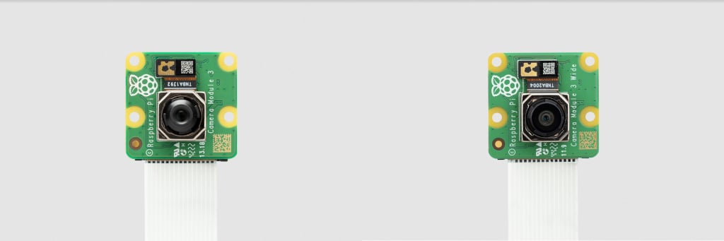
Camera Module 3
Edit this on GitHub
This 12-megapixel camera is built around the Sony IMX708 sensor with a resolution of 4608 × 2592 pixels. It has powered autofocus and can record an exposure time of up to 112 seconds.
Camera Module 3 comes in the following variants:
-
Standard, normal field of view (FoV)
-
Standard, wide FoV
-
NoIR, normal FoV
-
NoIR, wide FoV
The standard variants capture visible light only; infrared light is filtered out. The NoIR variants don’t have an infrared filter; they capture both visible light and infrared light. Use a NoIR camera with infrared lighting to see in the dark or use it with the included square of blue gel to monitor the health of green plants.
All of these variants are also available for the standalone Camera Module 3 sensor assembly.

For detailed information about the hardware characteristics and capabilities of this camera, see the hardware specifications.
|
Note
|
There is some evidence to suggest that the Camera Module 3 might emit RFI at a harmonic of the CSI clock rate. This RFI is in a range to interfere with GPS L1 frequencies (1575 MHz). For details and proposed workarounds, see the thread on Github. |
Global Shutter Camera
Edit this on GitHub
The 1.6-megapixel Global Shutter Camera captures fast-moving subjects and minimises distortion. It’s built around the Sony IMX296 sensor with a resolution of 1456 × 1088 pixels.
The camera comes with a C/CS-mount for compatibility with a broad variety of lenses. For more information, see Lenses.
You can trigger the Global Shutter (GS) camera by pulsing the external trigger connection on the board. This feature enables you to synchronise multiple Global Shutter Cameras. For more information, see External Trigger on the Global Shutter Camera.

For detailed information about the hardware characteristics and capabilities of this camera, see the hardware specifications.
Rolling or Global shutter?
Most digital cameras, including our other Camera Modules, use a rolling shutter: they scan the image they’re capturing line-by-line, then output the results. This can cause distortion effects in some settings. For example, a photo of rotating propeller blades can make the image look as though it’s shimmering rather than like an object that’s rotating. This is because the propeller blades have had enough time to change position in the tiny moment that the camera has taken to scan across and observe the scene.
A global shutter, like the one on our Global Shutter Camera Module, doesn’t do this. It captures the light from every pixel in the scene at once, so a photograph of something like propeller blades doesn’t result in the same distortion.
This is useful because it makes fast-moving objects, like propeller blades, easy to capture; we can also synchronise several cameras to take a photo at precisely the same moment in time. Benefits include minimising distortion when capturing stereo images; the human brain is confused if any movement that appears in the left eye hasn’t yet appeared in the right eye. The Raspberry Pi Global Shutter Camera can also operate with shorter exposure times – down to 30 µs, given enough light – than a rolling shutter camera, which makes it useful for high-speed photography.
|
Note
|
The Global Shutter Camera’s image sensor has a 6.3 mm diagonal active sensing area, which is similar in size to Raspberry Pi’s HQ Camera. However, the pixels are larger and can collect more light. Large pixel size and low pixel count are valuable in machine-vision applications; the more pixels a sensor produces, the harder it is to process the image in real time. To get around this, many applications downsize and crop images. This is unnecessary with the Global Shutter Camera and the appropriate lens magnification, where the lower resolution and large pixel size mean an image can be captured natively. |
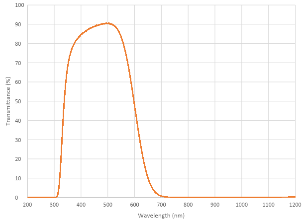
Transmission characteristics
The Global Shutter Camera uses a Hoya CM500 infrared filter. Its transmission characteristics are as represented in the following graph.
If you want to enhance the Global Shutter Camera’s sensitivity to infrared light, you can remove the infrared filter. This action is permanent and voids the warranty. For more information, see IR filter.
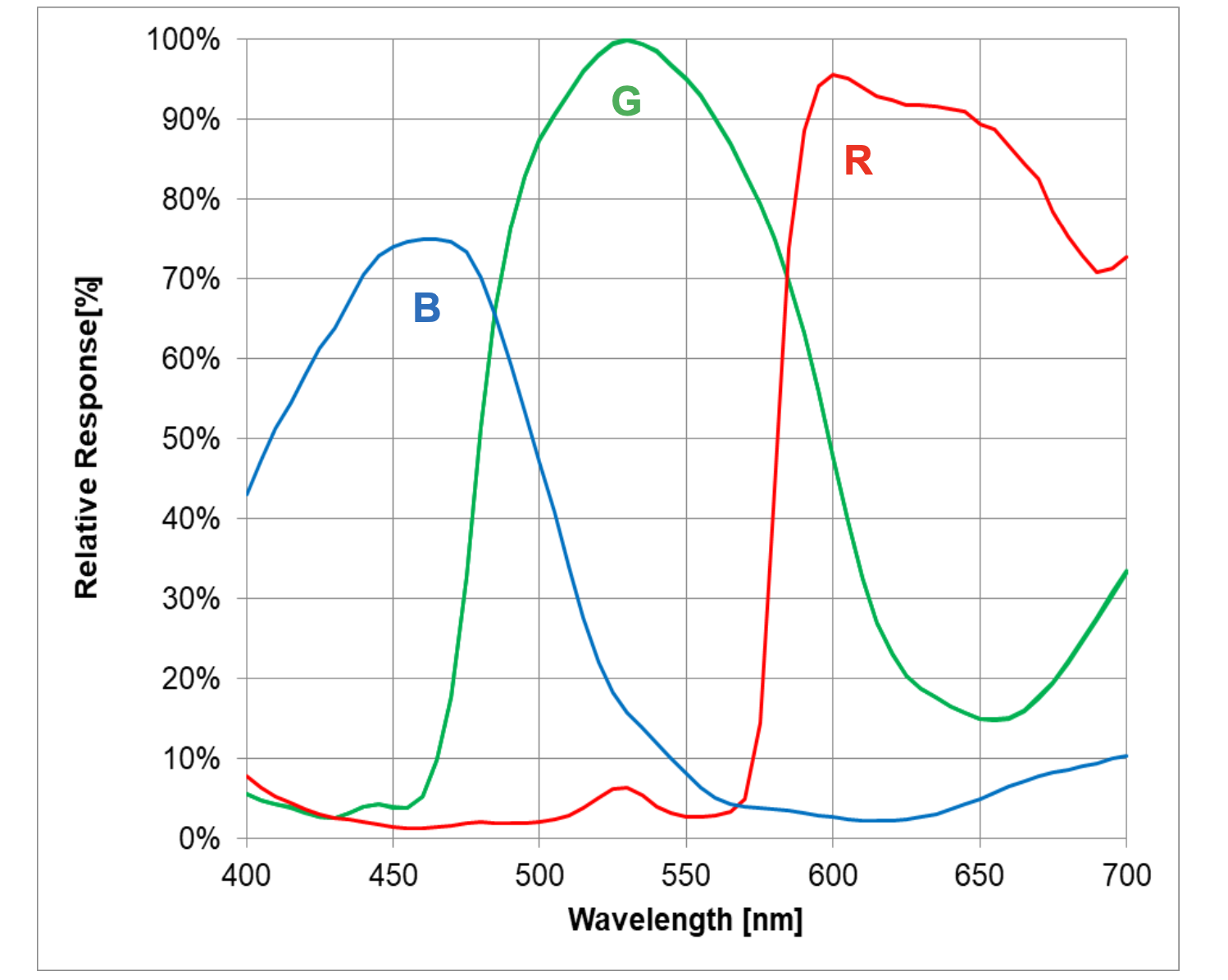
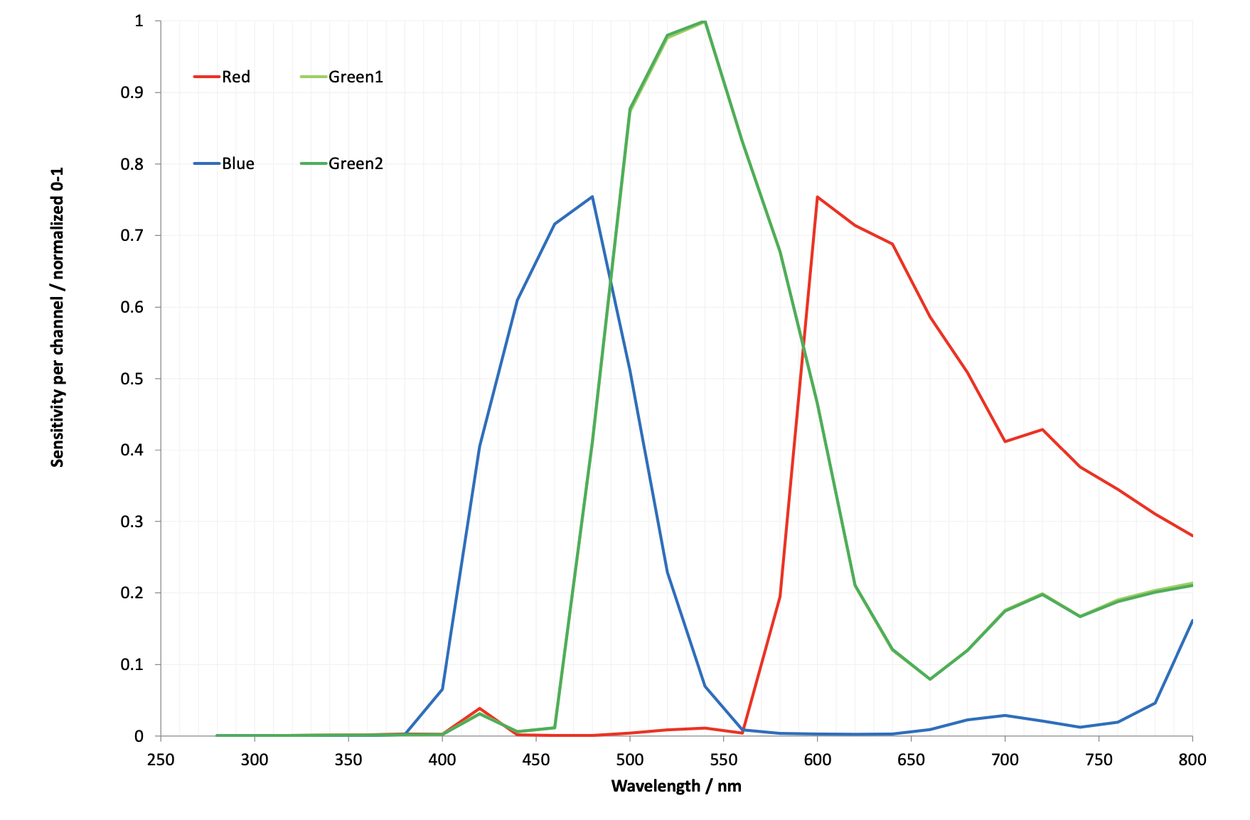
Without its filter, Raspberry Pi Global Shutter Camera has the following transmission characteristics:
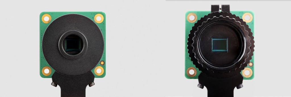
High Quality Camera
Edit this on GitHub
The 12-megapixel High Quality Camera comes with either an M12-mount or a C/CS-mount for compatibility with a broad variety of lenses. For more information, see Lenses. The camera is built around the Sony IMX477 sensor with a resolution of 4056 × 3040 pixels. It can record an exposure time of up to 670.74 seconds.
You can trigger the High Quality Camera by pulsing the external trigger. This feature enables you to synchronise multiple High Quality Cameras. For more information, see Synchronous Captures.
For detailed information about the hardware characteristics and capabilities of this camera, see the hardware specifications.
Transmission characteristics
The High Quality Camera uses a Hoya CM500 infrared filter. Its transmission characteristics are as represented in the following graph.
If you want to enhance the High Quality Camera’s sensitivity to infrared light, you can remove the infrared filter. This action is permanent and voids the warranty. For more information, see IR filter.
Without its filter, Raspberry Pi High Quality Camera has the following transmission characteristics:

Recommended Lenses
Edit this on GitHub
The following lenses are recommended for use with our HQ and GS cameras.
|
Note
|
While the HQ Camera is available in both C/CS- and M12-mount versions, the GS Camera is available only with a C/CS-mount. |
C/CS Lenses
We recommend two lenses, a 6 mm wide angle lens and a 16 mm telephoto lens manufactured by CGL Electronics Co. Ltd. These lenses should be available from your nearest Authorised Reseller.
| 16 mm telephoto | 6 mm wide angle | ||
|---|---|---|---|
Resolution |
10 MP |
3 MP |
|
Image format |
1" |
1/2" |
|
Aperture |
F1.4 to F16 |
F1.2 |
|
Mount |
C |
CS |
|
Field of View H°×V° (D°) |
HQ |
22.2°×16.7° (27.8°) |
55°×45° (71°) |
GS |
17.8°×13.4° (22.3) |
45°×34° (56°) |
|
Back focal length |
17.53 mm |
7.53 mm |
|
M.O.D. |
0.2m |
0.2m |
|
Dimensions |
φ39×50 mm |
φ30×34 mm |
|
M12 Lenses

We recommend three lenses manufactured by Gaojia Optotech. These lenses should be available from your nearest Authorised Reseller.
| 8 mm | 25 mm | Fish Eye | ||
|---|---|---|---|---|
Resolution |
12 MP |
5 MP |
15 MP |
|
Image format |
1/1.7" |
1/2" |
1/2.3" |
|
Aperture |
F1.8 |
F2.4 |
F2.5 |
|
Mount |
M12 |
|||
HQ Field of View H°×V° (D°) |
49°×36° (62°) |
14.4°×10.9° (17.9)° |
140°×102.6° (184.6°) |
|
Synchronous Captures
Edit this on GitHub
The High Quality (HQ) Camera supports synchronous captures. One camera (the "source") can be configured to generate a pulse on its XVS (Vertical Sync) pin when a frame capture is initiated. Other ("sink") cameras can listen for this pulse, and capture a frame at the same time as the source camera.
This method is largely superseded by software camera synchronisation which can operate over long distances without additional wires and has sub-millisecond accuracy. But when cameras are physically close, wired synchronisation may be used.
|
Note
|
You can also operate Global Shutter (GS) Cameras in synchronous mode. However, the source camera records one extra frame. Instead, for GS Cameras we recommend using an external trigger source. You can’t synchronise a GS Camera and an HQ Camera. |
Connecting the cameras
Solder a wire to the XVS test point of each camera, and connect them together.
Solder a wire to the GND test point of each camera, and connect them together.
For GS Cameras only, you must also connect the XHS (Horizontal Sync) test point of each camera together. On any GS Camera that you wish to act as a sink, bridge the two halves of the MAS pad with solder.
|
Note
|
An earlier version of this document recommended an external pull-up for XVS. This is no longer recommended. Instead, ensure you have the latest version of Raspberry Pi OS and set the always-on property for all connected cameras.
|
Driver configuration
Configure the camera drivers to keep their 1.8 V power supplies on when not streaming, and optionally to select the source and sink roles.
For the HQ Camera
Edit /boot/firmware/config.txt. Change camera_auto_detect=1 to camera_auto_detect=0.
Append this line for a source camera:
dtoverlay=imx477,always-on,sync-sourceOr for a sink:
dtoverlay=imx477,always-on,sync-sinkWhen using the CAM0 port on a Raspberry Pi 5, CM4 or CM5, append ,cam0 to that line without a space. If two cameras are on the same Raspberry Pi, you need two dtoverlay lines, only one of them ending with ,cam0.
Alternatively, if you wish to swap the cameras' roles at runtime (and they are not both connected to the same Raspberry Pi), omit ,sync-source or ,sync-sink above. Instead you can set a module parameter before starting each camera:
For the Raspberry Pi with the source camera:
$ echo 1 | sudo tee /sys/module/imx477/parameters/trigger_modeFor the Raspberry Pi with the sink camera:
$ echo 2 | sudo tee /sys/module/imx477/parameters/trigger_modeDo this every time the system is booted.
For the GS Camera
Edit /boot/firmware/config.txt. Change camera_auto_detect=1 to camera_auto_detect=0.
For either a source or a sink, append this line:
dtoverlay=imx296,always-onWhen using the CAM0 port on a Raspberry Pi 5, CM4 or CM5, append ,cam0 to that line without a space. If two cameras are on the same Raspberry Pi, you need two dtoverlay lines, only one of them ending with ,cam0.
On the GS Camera, the sink role is enabled by the MAS pin and can’t be configured by software ("trigger_mode" and "sync-sink" relate to the external trigger method, and mustn’t be set for this method).
Libcamera configuration
If the cameras don’t all start within 1 second, the rpicam applications can time out. To prevent this, edit a configuration file on any Raspberry Pi with sink cameras.
On Raspberry Pi 5 or CM5:
$ cp /usr/share/libcamera/pipeline/rpi/pisp/example.yaml timeout.yamlOn other Raspberry Pi models:
$ cp /usr/share/libcamera/pipeline/rpi/vc4/rpi_apps.yaml timeout.yamlNow edit the copy. In both cases, delete the # (comment) from the "camera_timeout_value_ms": line, and change the number to 60000 (60 seconds).
Starting the cameras
Run the following commands to start the sink:
$ export LIBCAMERA_RPI_CONFIG_FILE=timeout.yaml
$ rpicam-vid --frames 300 --qt-preview -o sink.h264
Wait a few seconds, then run the following command to start the source:
$ rpicam-vid --frames 300 --qt-preview -o source.h264Frames should be synchronised. Use --frames to ensure the same number of frames are captured, and that the recordings are exactly the same length.
Running the sink first ensures that no frames are missed.
|
Note
|
When using the GS camera in synchronous mode, the sink doesn’t record exactly the same number of frames as the source. The source records one extra frame before the sink starts recording. Because of this, you need to specify that the sink records one less frame with the --frames option.
|
External Trigger on the Global Shutter Camera
Edit this on GitHub
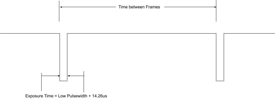
The Global Shutter (GS) camera can be triggered externally by pulsing the external trigger connection on the board (denoted on the board as XTR). Multiple cameras can be connected to the same pulse, allowing for an alternative way to synchronise two cameras.
The exposure time is equal to the low pulse-width time plus an additional 14.26 μs. For example, a low pulse of 10000 μs leads to an exposure time of 10014.26 μs. Framerate is directly controlled by how often you pulse the pin. A PWM frequency of 30 Hz leads to a framerate of 30 frames per second.
Preparation
|
Warning
|
This modification includes removing an SMD soldered part. You should not attempt this modification unless you feel you are competent to complete it. When soldering to the Camera board, please remove the plastic back cover to avoid damaging it. |
If your board has transistor Q2 fitted (shown in blue on the image below), then you will need to remove R11 from the board (shown in red). This connects GP1 to XTR and without removing R11, the camera will not operate in external trigger mode. The location of the components is displayed below.

Next, solder a wire to the touchpoints of XTR and GND on the GS Camera board. Note that XTR is a 1.8 V input, so you may need a level shifter or potential divider.
We can use a Raspberry Pi Pico to provide the trigger. Connect any Pico GPIO pin (GP28 is used in this example) to XTR via a 1.5 kΩ resistor. Also connect a 1.8 kΩ resistor between XTR and GND to reduce the high logic level to 1.8 V. A wiring diagram is shown below.

Raspberry Pi Pico MicroPython Code
from machine import Pin, PWM

from time import sleep

pwm = PWM(Pin(28))

framerate = 30
shutter = 6000  # In microseconds

frame_length = 1000000 / framerate
pwm.freq(framerate)

pwm.duty_u16(int((1 - (shutter - 14) / frame_length) * 65535))
The low pulse width is equal to the shutter time, and the frequency of the PWM equals the framerate.
|
Note
|
In this example, Pin 28 connects to the XTR touchpoint on the GS camera board. |
Camera driver configuration
This step is only necessary if you have more than one camera with XTR wired in parallel.
Edit /boot/firmware/config.txt. Change camera_auto_detect=1 to camera_auto_detect=0.
Append this line:
dtoverlay=imx296,always-onWhen using the CAM0 port on a Raspberry Pi 5, CM4 or CM5, append ,cam0 to that line without a space. If both cameras are on the same Raspberry Pi you will need two dtoverlay lines, only one of them ending with ,cam0.
If the external trigger will not be started right away, you also need to increase the libcamera timeout as above.
Starting the camera
Enable external triggering:
$ echo 1 | sudo tee /sys/module/imx296/parameters/trigger_modeRun the code on the Pico, then set the camera running:
$ rpicam-hello -t 0 --qt-preview --shutter 3000Every time the Pico pulses the pin, it should capture a frame. However, if --gain and --awbgains are not set, some frames will be dropped to allow AGC and AWB algorithms to settle.
|
Note
|
When running rpicam-apps, always specify a fixed shutter duration, to ensure the AGC does not try to adjust the camera’s shutter speed. The value is not important, since it is actually controlled by the external trigger pulse.
|
IR Filter
Edit this on GitHub
Both the High Quality Camera and Global Shutter Camera contain an IR filter to reduce the camera’s sensitivity to infrared light and help outdoor photos look more natural. However, you may remove the filter to:
-
Enhance colours in certain types of photography, such as images of plants, water, and the sky
-
Provide night vision in a location that is illuminated with infrared light
Filter Removal
|
Warning
|
This procedure cannot be reversed: the adhesive that attaches the filter will not survive being lifted and replaced, and while the IR filter is about 1.1 mm thick, it may crack when it is removed. Removing it will void the warranty on the product. |
You can remove the filter from both the HQ and GS cameras. The HQ camera is shown in the demonstration below.

|
Important
|
To protect the sensor when exposed to the air, ensure that you’re working in a clean and dust-free environment. |
-
Unscrew the two 1.5 mm hex lock keys on the underside of the main circuit board. Be careful not to let the washers roll away.

-
There’s a gasket of slightly sticky material between the housing and PCB that requires some force to separate. You may try some ways to weaken the adhesive, such as a little isopropyl alcohol or heat (~20-30°C).
-
When the adhesive is loose, lift up the board and place it down on a very clean surface. Make sure the sensor doesn’t touch the surface.

-
Face the lens upwards and place the mount on a flat surface.

-
To minimise the risk of breaking the filter, use a pen top or similar soft plastic item to push down on the filter only at the very edges where the glass attaches to the aluminium. The glue will break and the filter will detach from the lens mount.

-
Given that changing lenses will expose the sensor, at this point you could affix a clear filter (for example, OHP plastic) to minimize the chance of dust entering the sensor cavity.
-
Replace the main housing over the circuit board. Be sure to realign the housing with the gasket, which remains on the circuit board.
-
Apply the nylon washer first to prevent damage to the circuit board.
-
Next, fit the steel washer, which prevents damage to the nylon washer. Screw down the two hex lock keys. As long as the washers have been fitted in the correct order, they do not need to be screwed very tightly.

|
Note
|
It is likely to be difficult or impossible to glue the filter back in place and return the device to functioning as a normal optical camera. |
Hardware specifications
Edit this on GitHub
The following table compares the features and capabilities of the Raspberry Pi camera hardware.
| Camera Module 1 | Camera Module 2 | Camera Module 3 | Camera Module 3 Wide | HQ Camera | AI Camera | GS Camera | |
|---|---|---|---|---|---|---|---|
Size |
Around 25 × 24 × 9 mm |
Around 25 × 24 × 9 mm |
Around 25 × 24 × 11.5 mm |
Around 25 × 24 × 12.4 mm |
38 × 38 × 18.4 mm (excluding lens) |
25 × 24 × 11.9 mm |
38 × 38 × 19.8 mm (29.5 mm with adaptor and dust cap) |
Weight |
3 g |
3 g |
4 g |
4 g |
30.4 g |
6 g |
34 g (41 g with adaptor and dust cap) |
Still resolution |
5 megapixels |
8 megapixels |
11.9 megapixels |
11.9 megapixels |
12.3 megapixels |
12.3 megapixels |
1.58 megapixels |
Video modes |
1080p30, 720p60 and 640 × 480p60/90 |
1080p47, 1640 × 1232p41 and 640 × 480p206 |
2304 × 1296p56, 2304 × 1296p30 HDR, 1536 × 864p120 |
2304 × 1296p56, 2304 × 1296p30 HDR, 1536 × 864p120 |
2028 × 1080p50, 2028 × 1520p40 and 1332 × 990p120 |
2028 × 1520p30, 4056 × 3040p10 |
1456 × 1088p60 |
Sensor |
OmniVision OV5647 |
Sony IMX219 |
Sony IMX708 |
Sony IMX708 |
Sony IMX477 |
Sony IMX500 |
Sony IMX296 |
Sensor resolution |
2592 × 1944 pixels |
3280 × 2464 pixels |
4608 × 2592 pixels |
4608 × 2592 pixels |
4056 × 3040 pixels |
4056 × 3040 pixels |
1456 × 1088 pixels |
Sensor image area |
3.76 × 2.74 mm |
3.68 × 2.76 mm (4.6 mm diagonal) |
6.45 × 3.63 mm (7.4 mm diagonal) |
6.45 × 3.63 mm (7.4 mm diagonal) |
6.287 × 4.712 mm (7.9 mm diagonal) |
6.287 × 4.712 mm (7.9 mm diagonal) |
6.3 mm diagonal |
Pixel size |
1.4 µm × 1.4 µm |
1.12 µm × 1.12 µm |
1.4 µm × 1.4 µm |
1.4 µm × 1.4 µm |
1.55 µm × 1.55 µm |
1.55 µm × 1.55 µm |
3.45 µm × 3.45 µm |
Optical size |
1/4" |
1/4" |
1/2.43" |
1/2.43" |
1/2.3" |
1/2.3" |
1/2.9" |
Focus |
Fixed |
Adjustable |
Motorised |
Motorised |
Adjustable |
Adjustable |
Adjustable |
Focus range |
Approx 1 m to ∞ |
Approx 10 cm to ∞ |
Approx 10 cm to ∞ |
Approx 5 cm to ∞ |
Depends on lens |
Approx 20 cm to ∞ |
Depends on lens |
Focal length |
3.60 mm ± 0.01 |
3.04 mm |
4.74 mm |
2.75 mm |
Depends on lens |
4.74 mm |
Depends on lens |
Horizontal Field of View (FoV) |
53.50 ± 0.13 degrees |
62.2 degrees |
66 degrees |
102 degrees |
Depends on lens |
66 ± 3 degrees |
Depends on lens |
Vertical Field of View (FoV) |
41.41 ± 0.11 degrees |
48.8 degrees |
41 degrees |
67 degrees |
Depends on lens |
52.3 ± 3 degrees |
Depends on lens |
Focal ratio (F-Stop) |
F2.9 |
F2.0 |
F1.8 |
F2.2 |
Depends on lens |
F1.79 |
Depends on lens |
Maximum exposure time (seconds) |
3.28 |
11.76 |
112 |
112 |
670.74 |
112 |
15.5 |
Lens Mount |
N/A |
N/A |
N/A |
N/A |
C/CS- or M12-mount |
N/A |
C/CS |
NoIR version available? |
Yes |
Yes |
Yes |
Yes |
No |
No |
No |
Advanced information
Edit this on GitHub
This section provides information for advanced users.
Mechanical drawings and schematics
Mechanical drawings and schematics are available on the Product Information Portal at the following locations:
|
Note
|
Board dimensions and mounting-hole positions for Camera Module 3 are identical to Camera Module 2. However, due to changes in the size and position of the sensor module, it isn’t mechanically compatible with the camera lid for the Raspberry Pi Zero case. |
In addition, the following figure shows the schematic for the Raspberry Pi CSI camera connector.
Pinout information
Use the information in this section to understand the function of the pins in the camera connectors.
Locating pin 1
The location of pin 1 on an FPC connector depends on the hardware.
The following descriptions assume you’re holding your Raspberry Pi board with the chip and connectors facing up and the Raspberry Pi logo in the correct orientation. For Raspberry Pi Zero boards without the logo on the top side, orient the board with the GPIO along the edge furthest away from you.
-
On Raspberry Pi flagship models and Raspberry Pi Zero devices, pin 1 is the pin furthest from you and closest to the GPIO header.
-
On Raspberry Pi Compute Module IO boards, pin 1 is marked with a small circle or dot depending on the model.
When holding the Raspberry Pi camera board with the lens facing down and the connector facing to your right, pin 1 is the pin closest to you.
Camera connector pinout (15-Pin)
This is the pinout of the 15-pin Camera Serial Interface (CSI) connector used on flagship Raspberry Pi models prior to Raspberry Pi 5. The connector is compatible with Amphenol SFW15R-2STE1LF.
Signal direction is specified from the perspective of the Raspberry Pi board. The I2C lines (SCL and SDA) are pulled up to 3.3 V on the Raspberry Pi board.
The function and direction of the GPIO lines depend on the specific Camera Module in use. Typically, CAM_IO0 is used as an active-high power enable. Some products don’t include CAM_IO1.
| Pin | Name | Description | Direction / Type |
|---|---|---|---|
1 |
GND |
- |
Ground |
2 |
CAM_DN0 |
D-PHY lane 0 (negative) |
Input, D-PHY |
3 |
CAM_DP0 |
D-PHY lane 0 (positive) |
Input, D-PHY |
4 |
GND |
- |
Ground |
5 |
CAM_DN1 |
D-PHY lane 1 (negative) |
Input, D-PHY |
6 |
CAM_DP1 |
D-PHY lane 1 (positive) |
Input, D-PHY |
7 |
GND |
- |
Ground |
8 |
CAM_CN |
D-PHY Clock (negative) |
Input, D-PHY |
9 |
CAM_CP |
D-PHY Clock (positive) |
Input, D-PHY |
10 |
GND |
- |
Ground |
11 |
CAM_IO0 |
GPIO (for example, Power-Enable) |
Bidirectional, 3.3 V |
12 |
CAM_IO1 |
GPIO (for example, Clock, LED) |
Bidirectional, 3.3 V |
13 |
SCL |
I2C Clock |
Bidirectional, 3.3 V |
14 |
SDA |
I2C Data |
Bidirectional, 3.3 V |
15 |
3V3 |
3.3 V Supply |
Output |

Camera connector pinout (22-Pin)
This is the pinout of the 22-pin Camera Serial Interface (CSI) connector used on the Raspberry Pi Zero series, the Compute Module IO boards, and flagship models since Raspberry Pi 5. The connector is compatible with Amphenol F32Q-1A7H1-11022.
Signal direction is specified from the perspective of the Raspberry Pi board. The I2C lines (SCL and SDA) are pulled up to 3.3 V on the Raspberry Pi board.
The function and direction of the GPIO lines depend on the specific Camera Module in use. Typically, CAM_IO0 is used as an active-high power enable. Some products don’t include CAM_IO1.
| Pin | Name | Description | Direction / Type |
|---|---|---|---|
1 |
GND |
- |
Ground |
2 |
CAM_DN0 |
D-PHY lane 0 (negative) |
Input, D-PHY |
3 |
CAM_DP0 |
D-PHY lane 0 (positive) |
Input, D-PHY |
4 |
GND |
- |
Ground |
5 |
CAM_DN1 |
D-PHY lane 1 (negative) |
Input, D-PHY |
6 |
CAM_DP1 |
D-PHY lane 1 (positive) |
Input, D-PHY |
7 |
GND |
- |
Ground |
8 |
CAM_CN |
D-PHY Clock (negative) |
Input, D-PHY |
9 |
CAM_CP |
D-PHY Clock (positive) |
Input, D-PHY |
10 |
GND |
- |
Ground |
11 |
CAM_DN2 |
D-PHY lane 2 (negative) |
Input, D-PHY |
12 |
CAM_DP2 |
D-PHY lane 2 (positive) |
Input, D-PHY |
13 |
GND |
- |
Ground |
14 |
CAM_DN3 |
D-PHY lane 3 (negative) |
Input, D-PHY |
15 |
CAM_DP3 |
D-PHY lane 3 (positive) |
Input, D-PHY |
16 |
GND |
- |
Ground |
17 |
CAM_IO0 |
GPIO (for example, Power-Enable) |
Bidirectional, 3.3 V |
18 |
CAM_IO1 |
GPIO (for example, Clock, LED) |
Bidirectional, 3.3 V |
19 |
GND |
- |
Ground |
20 |
SCL |
I2C Clock |
Bidirectional, 3.3 V |
21 |
SDA |
I2C Data |
Bidirectional, 3.3 V |
22 |
3V3 |
3.3 V Supply |
Output |