Audio HATs
Overview
Edit this on GitHub
Raspberry Pi Audio Boards bring high quality audio to your existing hi-fi or Raspberry Pi-based equipment and projects. We offer four different Hardware Attached on Top (HAT) options that will fit any Raspberry Pi using the 40-pin GPIO header.
Each board has a specific purpose and set of features. The highest audio quality playback is available from our DAC PRO, DAC+ and DigiAMP+ boards, which support up to full HD audio (192 kHz); while the Codec Zero supports up to HD audio (96 kHz) and includes a built-in microphone, making it ideal for compact projects.
Features at a glance
| Line out | Balanced out | Stereo speakers | Mono speaker | Headphones | Aux in | Aux out | Ext mic | Built-in mic | |
|---|---|---|---|---|---|---|---|---|---|
DAC Pro |
✓ |
✓ |
✓ |
||||||
DAC+ |
✓ |
✓ |
|||||||
DigiAmp+ |
✓ |
||||||||
Codec Zero |
✓ |
✓ |
✓ |
✓ |
✓ |
- Line out
-
A double phono/RCA connector, normally red and white in colour. This output is a variable analogue signal (0-2V RMS) and can connect to your existing hi-fi (pre-amp or amplifier), or can be used to drive active speakers which have their own amplifier built in.
- Balanced out
-
An XLR connector, normally a three-pin male connector. This is used in a studio set-up, and in some high-end hi-fi systems. It can also be used to drive active monitor speakers like those used at clubs or on stage directed towards the DJ or performers.
- Stereo speakers
-
Two sets of screw terminals for 2 × 25 W speakers. These are for traditional hi-fi speakers without built-in amplification. These are known as passive speakers.
- Mono speaker
-
A screw terminal for a single 1.2 W speaker, as found in a transistor radio or similar.
- Headphones
-
A 3.5 mm jack socket delivering stereo audio for a set of headphones. The headphone amplifiers on the Raspberry Pi DAC boards can drive up to 80/90 Ω impedance headphones.
- Aux in
-
A double Phono/RCA connector or 3.5 mm socket. Accepts analogue audio in up to 1V RMS. This can be used to record audio from a variable analogue source such as a mobile phone, MP3 player or similar.
- Aux out
-
A double Phono/RCA connector or 3.5 mm socket. Delivers analogue audio out up to 1V RMS. This can be used to feed audio into an amplifier at a reduced volume compared to Line out.
- Ext mic
-
A 3.5 mm socket for use with an external electret microphone. The built-in MEMS microphone on the Codec Zero is automatically disabled when the external Mic in connector is used.
Raspberry Pi DAC Pro
Edit this on GitHub
The Raspberry Pi DAC Pro HAT is our highest-fidelity digital to analogue converter (DAC).
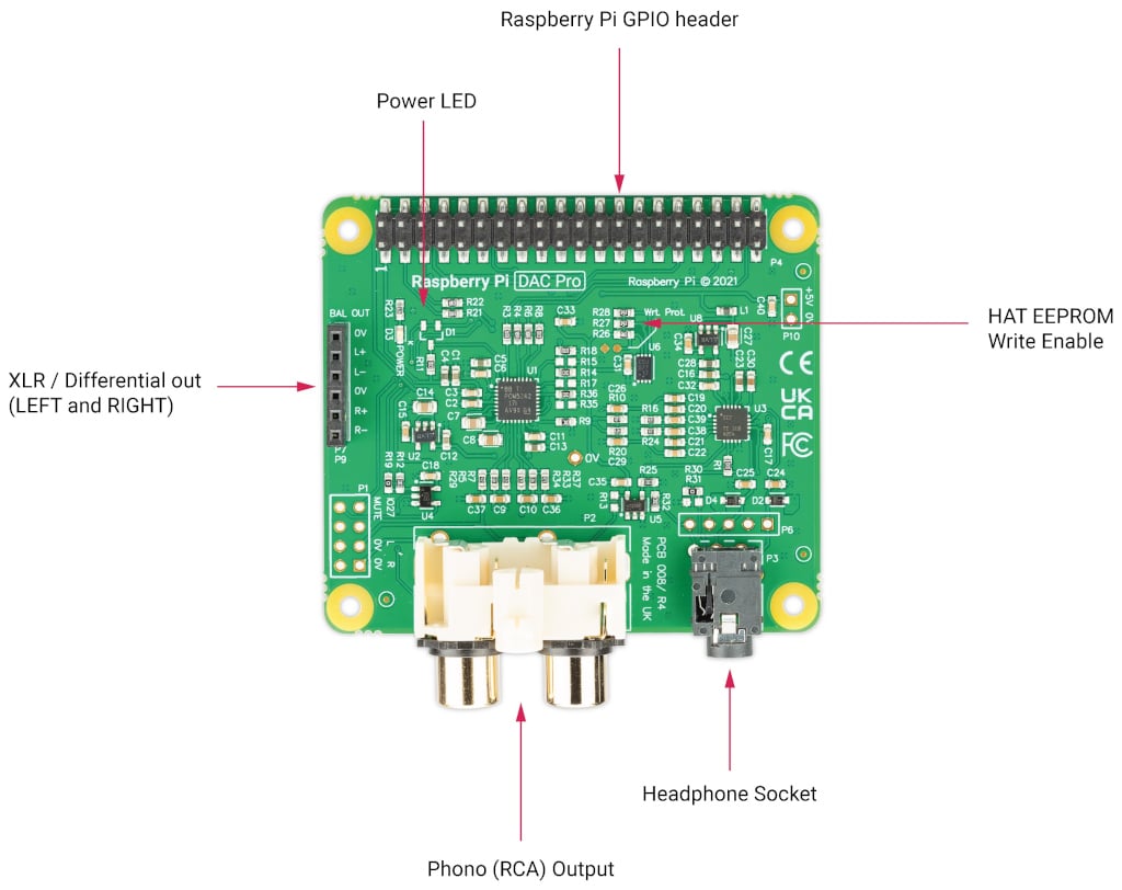
With the Texas Instruments PCM5242, the DAC Pro provides outstanding signal-to-noise ratio (SNR) and supports balanced/differential output in parallel to phono/RCA line-level output. It also includes a dedicated headphone amplifier. The DAC Pro is powered by a Raspberry Pi through the GPIO header.
As part of the DAC Pro, two three-pin headers (P7/P9) are exposed above the Raspberry Pi device’s USB and Ethernet ports for use by the optional XLR board, allowing differential/balanced output.
Pinouts
P1 |
Analogue out (0-2V RMS), carries GPIO27, MUTE signal (headphone detect), left and right audio and left and right ground. |
P6 |
Headphone socket signals (1: LEFT, 2: GROUND, 3: RIGHT, 4: GROUND, 5: DETECT). |
P7/9 |
Differential (0-4V RMS) output (P7: LEFT, P9: RIGHT). |
P10 |
Alternative 5V input, powering Raspberry Pi in parallel. |
Optional XLR Board
The Pi-DAC PRO exposes a 6 pin header used by the optional XLR board to provide Differential / Balanced output exposed by XLR sockets above the Raspberry Pi device’s USB/Ethernet ports.
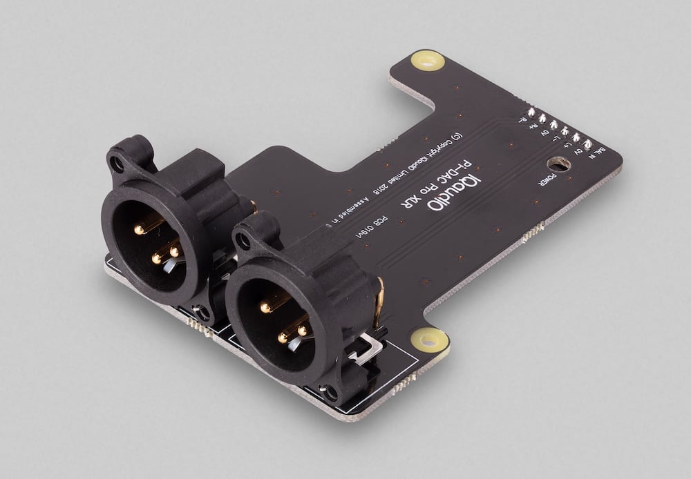
An XLR connector is used in Studio and some hi-end hifi systems. It can also be used to drive ACTIVE "monitor" speakers as used at discos or on stage.
Raspberry Pi DAC+
Edit this on GitHub
Raspberry Pi DAC+ is a high-resolution audio output HAT that provides 24-bit 192 kHz digital audio output.
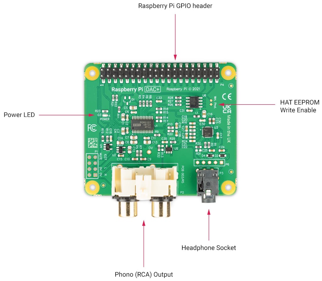
A Texas Instruments PCM5122 is used in the DAC+ to deliver analogue audio to the phono connectors of the device. It also supports a dedicated headphone amplifier and is powered by the Raspberry Pi through the GPIO header.
Raspberry Pi DigiAMP+
Edit this on GitHub
With Raspberry Pi DigiAMP+, you can connect 2 passive stereo speakers up to 35 W with variable output, making it ideal for use in Raspberry Pi-based hi-fi systems.
DigiAMP+ uses the Texas Instruments TAS5756M PowerDAC and must be powered from an external supply.
It requires a 12-24V DC power source (the XP Power VEC65US19 power supply is recommended).
|
Note
|
The DigiAMP+ is designed to work with Raspberry Pi 3 and earlier devices. If you use it with a Raspberry Pi 4 or later devices, use an externally-powered USB hub to prevent the USB ports from adding extra load to the device. Failure to do so is likely to result in a low power warning. |
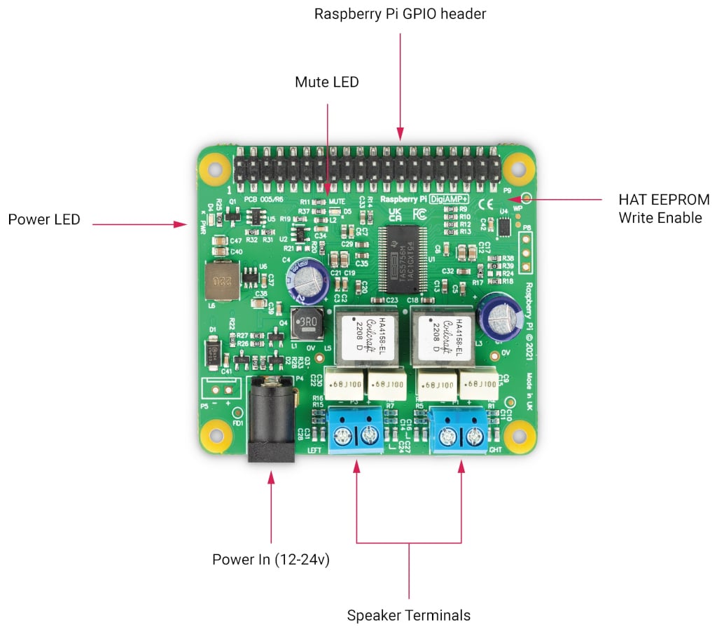
DigiAMP+'s power in barrel connector is 5.5 mm × 2.5 mm.
At power-on, the amplifier is muted by default (the mute LED is illuminated). Software is responsible for the mute state and LED control (Raspberry Pi GPIO22).
DigiAMP+ is designed to provide power to the Raspberry Pi and DigiAMP+ together in parallel, delivering 5.1V at 2.5amp to the Raspberry Pi through the GPIO header.
|
Warning
|
Don’t apply power to the Raspberry Pi device’s own power input when using DigiAMP+. |
Raspberry Pi Codec Zero
Edit this on GitHub
Raspberry Pi Codec Zero is a Raspberry Pi Zero-sized audio HAT. It delivers bi-directional digital audio signals (I2S) between a Raspberry Pi and the Codec Zero’s on-board Dialog Semiconductor DA7212 codec. The Codec Zero supports a range of input and output devices.
-
High performance 24-bit audio codec
-
Supports common audio sample rates between 8-96 kHz
-
Built in micro-electro-mechanical (MEMS) microphone (Mic2)
-
Mono electret microphone (Mic2 left)
-
Automatic MEMS disabling on Mic2 insert detect
-
Supports additional (no fit) mono electret microphone (Mic1 right)
-
Stereo auxiliary input channel (AUX IN) – PHONO/RCA connectors
-
Stereo auxiliary output channel (Headphone/AUX OUT)
-
Flexible analogue and digital mixing paths
-
Digital signal processors (DSP) for automatic level control (ALC)
-
Five-band EQ
-
Mono line-out/mini speaker driver: 1.2 W at 5 V, THD < 10%, R = 8 Ω

The Codec Zero includes an EEPROM which can be used for auto-configuration of the Linux environment if necessary. It has an integrated MEMS microphone, and can be used with stereo microphone input through a 3.5 mm socket and a mono speaker (1.2W/8Ω).
In addition to the green (GPIO23) and red (GPIO24) LEDs, a tactile programmable button (GPIO27) is also provided.

Attach, connect, and configure
Edit this on GitHub
Raspberry Pi audio boards are designed to be plug-and-play with Raspberry Pi devices running Raspberry Pi OS, as they feature a pre-programmed EEPROM. They belong to a family of devices known as HATs (Hardware Attached on Top).
They can also be used with a headless (remote) setup.
Attach and connect the audio board
Raspberry Pi audio boards attach to the 40-pin GPIO header and are designed to be supported using the supplied circuit board standoffs and screws. All necessary mounting hardware, including spacers, screws, and connectors, is provided.
Soldering isn’t required for normal operation, but might be if you want to hard-wire specific connectors (External Line Return connections on the DAC Pro, for example).
To attach the audio board:
-
Screw the PCB spacers finger-tight onto your Raspberry Pi device.
-
Fit the audio board onto the 40-pin GPIO header.
-
From above the board, screw in the remaining screws.
Check hardware version
There are multiple versions of Raspberry Pi audio boards. The version determines the actions required for configuration.
Older IQaudIO-branded boards have a black PCB. Newer Raspberry Pi-branded boards have a green PCB. These boards are electrically equivalent, but have different EEPROM contents.
To check the version of your audio board:
-
Attach the audio board to your Raspberry Pi and apply power to it.
-
Check that the power LED on the audio board is illuminated, if it has one. For example, the Codec Zero has an LED marked
PWR. -
On the Raspberry Pi device, use the Terminal to enter the following command:
$ grep -a . /proc/device-tree/hat/*The Terminal returns one of the following strings:
-
Raspberry Pi Ltd.
-
IQaudIO Limited.
-
No such file or directory
No further action is required (see below for Extra Codec Zero configuration).
No further action is required (see below for Extra Codec Zero configuration).
The HAT isn’t detected. Do the following:
-
Power down the device.
-
Check the physical connections between the HAT and the Raspberry Pi device.
-
Power on the device, then repeat Step 3 in the preceding section.
-
If the same string is returned, open
config.txton your Raspberry Pi device. -
Add the following lines to cancel loading the default HAT overlay and apply the correct device tree overlay:
# Suppress the default HAT overlay: dtoverlay= # Add ONE of the following: dtoverlay=rpi-codeczero dtoverlay=rpi-dacplus dtoverlay=rpi-dacpro dtoverlay=rpi-digiampplus -
Save and close the file.
-
Reboot your Raspberry Pi to make the changes take effect.
Configure the audio board
After you’ve attached and connected your audio board to your Raspberry Pi device, you can switch between using it and the on-board device for audio playback:
-
Right-click the audio settings in the top-right corner of your screen.
-
Switch between the on-board audio settings and the HAT audio settings.

You can also disable the on-board audio device, which makes the Raspberry Pi audio board the primary audio device in Raspberry Pi OS.
The command-line method described below is useful if you’re running a headless setup (or Raspberry Pi OS Lite) and can’t control the audio board through the graphical Raspberry Pi OS desktop interface.
To disable the on-board audio device using SSH:
-
Connect to your Raspberry Pi device using SSH.
-
Run the following command to edit the file:
$ sudo nano /boot/firmware/config.txt -
Find the
dtparam=audio=online in the file and comment it out by placing a#symbol at the start of the line.The program disregards anything written after the
#symbol on any given line. Your/boot/firmware/config.txtfile now includes the following entry:#dtparam=audio=on -
Press Ctrl+X, then Y, then Enter to save.
-
Reboot your Raspberry Pi for the settings to take effect:
$ sudo reboot
Extra Codec Zero configuration
Raspberry Pi Codec Zero uses the Dialog Semiconductor DA7212 codec.
This allows the recording of audio from the built-in MEMS microphone, from stereo headers (AUX IN), or from two mono external electret microphones.
Playback is through stereo headers (AUX OUT) or a mono speaker connector.
Each input and output device has its own mixer, allowing audio levels and volume to be adjusted independently. Within the codec itself, other mixers and switches exist to allow the output to be mixed to a single mono channel for single-speaker output. Signals can also be inverted; there’s a five-band equaliser to adjust certain frequency bands. You can control these settings interactively using AlsaMixer, or programmatically.
Both AUX IN and AUX OUT are 1 V RMS. You might need to adjust the mixer for AUX IN to ensure the input signal doesn’t saturate the ADC. Similarly, adjust the output mixers to get the best possible output.
Preconfigured scripts (loadable ALSA settings) are available on GitHub, offering:
-
Mono MEMS microphone recording, mono speaker playback.
-
Mono MEMS microphone recording, mono AUX OUT playback.
-
Stereo AUX IN recording, stereo AUX OUT playback
-
Stereo MIC1/MIC2 recording, stereo AUX OUT playback
Codec Zero needs to know which of these input and output settings are used each time your Raspberry Pi powers on.
To provide the codec with input and output settings:
-
If
gitisn’t installed, open the Terminal and run the following command:$ sudo apt install git -
In a terminal session, run the following command to clone the scripts:
$ git clone https://github.com/raspberrypi/Pi-Codec.git -
Run the following command to set your device to use the on-board MEMS microphone for input and speaker playback for output, replacing
<username>with your username:$ sudo alsactl restore -f /home/<username>/Pi-Codec/Codec_Zero_OnboardMIC_record_and_SPK_playback.stateThis command might result in harmless warnings, including:
-
"failed to import hw" or "snd_use_case_mgr_open"
-
"No state is present for card"
In most cases, you can safely ignore these warnings.
However, the following warnings can indicate a hardware failure:
-
"Remote I/O error"
-
-
To make sure your settings persist the next time you boot the Raspberry Pi device, edit the
/etc/rc.localfile:$ sudo nano /etc/rc.local -
Add the chosen script command above the
exit 0line.The file looks similar to the following:
#!/bin/sh # # rc.local # # This script is executed at the end of each multiuser runlevel. # Make sure that the script will "exit 0" on success or any other # value on error. # # In order to enable or disable this script just change the execution # bits. # # By default this script does nothing. sudo alsactl restore -f /home/<username>/Pi-Codec/Codec_Zero_OnboardMIC_record_and_SPK_playback.state exit 0 -
Press Ctrl+X, then Y, then Enter to save. Reboot for the settings to take effect:
$ sudo reboot
If you’re using your Raspberry Pi in a headless or command-line environment:
-
Create the following file in your home folder:
$ nano ~/.asoundrc -
Add the following lines to the file to route default playback and capture through the ALSA
plugplugin for automatic format and channel conversions:pcm.!default { type plug slave.pcm { type hw card Zero } } ctl.!default { type hw card Zero } -
Press Ctrl+X, then Y, then Enter to save.
-
Reboot again to complete the configuration:
$ sudo reboot
Audio frameworks
Like other modern Linux distributions, Raspberry Pi OS uses PulseAudio or PipeWire by default for audio control.
These frameworks can mix and switch audio from multiple sources, and provide a high-level API for audio applications. Many audio applications use these frameworks by default.
Only create ~/.asoundrc if an audio application needs to:
-
Communicate directly with ALSA.
-
Run in an environment where PulseAudio or PipeWire isn’t present.
This file can interfere with the UI view of underlying audio resources. We don’t recommend creating ~/.asoundrc when running the Raspberry Pi OS desktop. The UI might automatically remove this file if it exists.
Mute and unmute the DigiAMP+
The mute state on DigiAMP+ is toggled using GPIO22. The device tree overlay supports unmuting DigiAMP+ using additional parameters.
To apply a one-shot unmute when the kernel module loads:
For Raspberry Pi boards:
dtoverlay=rpi-digiampplus,unmute_ampFor IQaudIO boards:
dtoverlay=iqaudio-digiampplus,unmute_ampTo unmute the amplifier when an ALSA device is opened by a client and mute with a five-second delay when closed (reopening within the five-second window cancels the mute):
For Raspberry Pi boards:
dtoverlay=rpi-digiampplus,auto_mute_ampFor IQaudIO boards:
dtoverlay=iqaudio-digiampplus,auto_mute_ampIf you don’t want to control the mute state through the device tree, you can script your own solution.
The amplifier starts muted.
To unmute the amplifier:
$ pinctrl 22 op dhTo mute the amplifier again:
$ pinctrl 22 dlControlling the digital volume
If you’re using the Raspberry Pi OS desktop environment, you can use the volume slider in the system tray.
To adjust the audio output volume on your audio board in a headless setup, use AlsaMixer:
$ alsamixerUse the left and right arrow keys to select the volume channel you want to adjust, then use the up and down arrow keys to adjust the volume. Press Esc to exit AlsaMixer.
Getting started
Edit this on GitHub
Create a toy chatter box
As an example of what Raspberry Pi Audio Boards can do, let’s walk through the creation of a toy chatter box. Its on-board microphone, programmable button and speaker driver make the Codec Zero an ideal choice for this application.
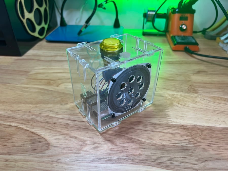
A random pre-recorded five-second audio clip will be played when the button is pressed. After holding for ten seconds, a notifying burp sound will be emitted, after which a new five-second clip will be recorded. Holding the button down for more than 20 seconds will play a second burp sound, and then erase all previous recordings.
Hardware and wiring
For this project, any small passive speaker is probably sufficient. We’re using one available here, which handles 5 W of power at 4 Ω. We have also used an illuminated momentary push button, and a laser-cut box to house all the components; but both are entirely optional. This example will work just using the Codec Zero’s on-board button, which is pre-wired to GPIO 27. (Alternatively, you can use any momentary push button, such as those available here.)
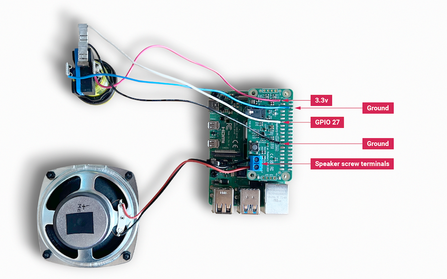
Use a small flat-head screwdriver to attach your speaker to the screw terminals. For the additional push button, solder the button wires directly to the Codec Zero pads as indicated, using GPIO pin 27 and Ground for the switch, and +3.3V and Ground for the LED, if necessary.
Set up your Raspberry Pi
In this example, we are using Raspberry Pi OS Lite. Refer to our guide on installing Raspberry Pi OS for more details.
Make sure that you update your operating system before proceeding and follow the instructions provided for Codec Zero configuration, including the commands to enable the on-board microphone and speaker output.
Program your Raspberry Pi
Open a shell — for instance by connecting over SSH — on your Raspberry Pi and run the following to create our Python script:
$ sudo nano chatter_box.pyAdd the following to the file, replacing <username> with your username:
#!/usr/bin/env python3
from gpiozero import Button
from signal import pause
import time
import random
import os
from datetime import datetime

# Print current date

date = datetime.now().strftime("%d_%m_%Y-%H:%M:%S")
print(f"{date}")

# Make sure that the 'sounds' folder exists, and if it does not, create it

path = '/home/<username>/sounds'

isExist = os.path.exists(path)

if not isExist:
  os.makedirs(path)
  print("The new directory is created!")
  os.system('chmod 777 -R /home/<username>/sounds')

# Download a 'burp' sound if it does not already exist

burp = '/home/<username>/burp.wav'

isExist = os.path.exists(burp)
if not isExist:
  os.system('wget http://rpf.io/burp -O burp.wav')
  print("Burp sound downloaded!")

# Setup button functions - Pin 27 = Button hold time 10 seconds.

button = Button(27, hold_time=10)

def pressed():
    global press_time
    press_time = time.time()
    print("Pressed at %s" % (press_time));

def released():
    release_time = time.time()
    pressed_for = release_time - press_time
    print("Released at %s after %.2f seconds" % (release_time, pressed_for))
    if pressed_for < button.hold_time:
        print("This is a short press")
        randomfile = random.choice(os.listdir("/home/<username>/sounds/"))
        file = '/home/<username>/sounds/' + randomfile
        os.system('aplay ' + file)
    elif pressed_for > 20:
        os.system('aplay ' + burp)
        print("Erasing all recorded sounds")
        os.system('rm /home/<username>/sounds/*');

def held():
    print("This is a long press")
    os.system('aplay ' + burp)
    os.system('arecord --format S16_LE --duration=5 --rate 48000 -c2 /home/<username>/sounds/$(date +"%d_%m_%Y-%H_%M_%S")_voice.m4a');

button.when_pressed = pressed
button.when_released = released
button.when_held = held

pause()
Press Ctrl+X, then the Y key, then Enter to save. To make the script executable, type the following:
$ sudo chmod +x chatter_box.pyNext, we need to create a crontab daemon that will automatically start the script each time the device is powered on. Run the following command to open your crontab for editing:
$ crontab -eYou’re asked to select an editor; we recommend you use nano. Select it by entering the corresponding number, and press Enter to continue. Add the following line to the bottom of the file, replacing <username> with your username:
@reboot python /home/<username>/chatter_box.py
Press Ctrl X, then Y, then Enter to save, then reboot your device with sudo reboot.
Use the toy chatter box
The final step is to ensure that everything is operating as expected. Press the button and release it when you hear the burp. The recording will now begin for a period of five seconds. After you release the button, press it briefly again to hear the recording. Repeat this process as many times as you wish, and your sounds will be played at random. You can delete all recordings by pressing and holding the button, keeping the button pressed during the first burp and recording process, and releasing it after at least 20 seconds, at which point you will hear another burp sound confirming that the recordings have been deleted.
Next steps
Upgrades! It is always fun to upgrade a project, so why not add some additional features, such as an LED that will illuminate when recording? This project has all the parts required to make your own version of a Google intelligent speaker system, or you might want to consider building a second device that can be used to create a pair of walkie-talkies that are capable of transferring audio files over a network by using SSH.
Hardware information
Edit this on GitHub
Hardware information:
-
PCB screws are all M2.5.
-
PCB standoffs (for case) are 5 mm male/female.
-
PCB standoffs (for Raspberry Pi to audio boards) are 9 mm female/female.
-
PCB standoffs (for XLR to DAC PRO) are 8 mm female/male.
-
PCB standoffs (for the official Raspberry Pi 7-inch display) are 5 mm male/female.
-
The rotary encoders we have used and tested are the Alpha three-pin rotary encoder RE160F-40E3-20A-24P, the ALPS EC12E2430804 (RS: 729-5848), and the Bourns ECW0JB24-AC0006L (RS: 263-2839).
-
The barrel connector used for powering the DigiAMP+ is 2.5 mm ID, 5.5 mm OD, 11 mm.
-
The DigiAMP+ is designed to operate with a 12V to 24V, 3A supply such as the XPPower VEC65US19 or similar.
-
The DigiAMP+ uses CamdenBoss two-part connectors. Those fitted to the PCB are CTBP9350/2AO.
-
The speaker terminal used on the Codec Zero will accept wires of between 14~26 AWG (wire of max 1.6 mm in diameter).
GPIO usage
Raspberry Pi audio boards take advantage of a number of pins on the GPIO header in order to operate successfully. Some of these pins are solely for the use of the board, and some can be shared with other peripherals, sensors, etc.
The following Raspberry Pi GPIO pins will be used by the audio boards:
-
All power pins
-
All ground pins
-
GPIO 2/3 (I2C)
-
GPIO 18/19/20/21 (I2S)
If appropriate then the following are also used:
-
GPIO 22 (DigiAMP+ mute/unmute support)
-
GPIO 23/24 for rotary encoder (physical volume control) or status LED (Codec Zero)
-
GPIO 25 for the IR Sensor
-
GPIO 27 for the rotary encoder push switch/Codec Zero switch
DAC PRO, DAC+, DigiAMP+, Codec Zero
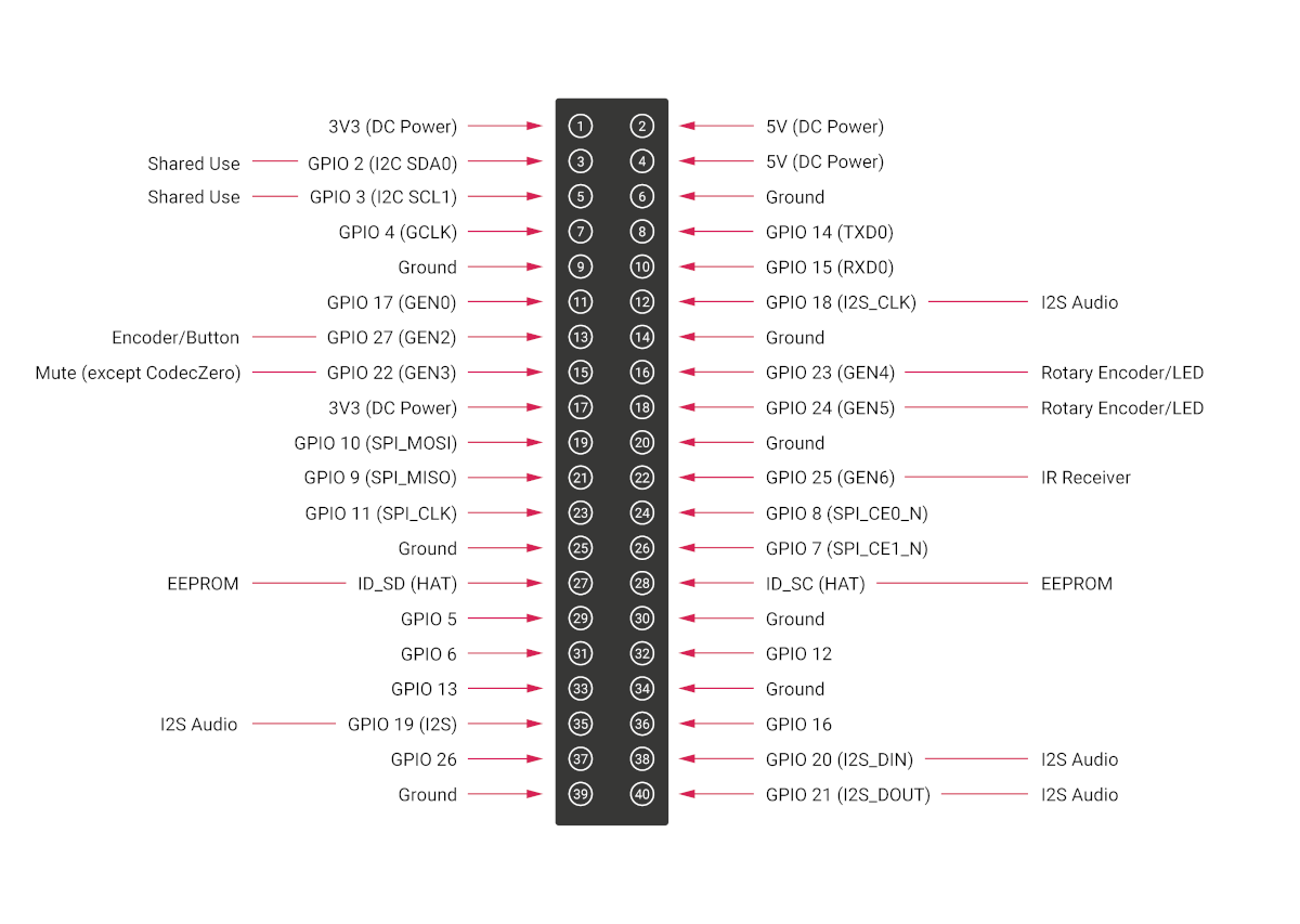
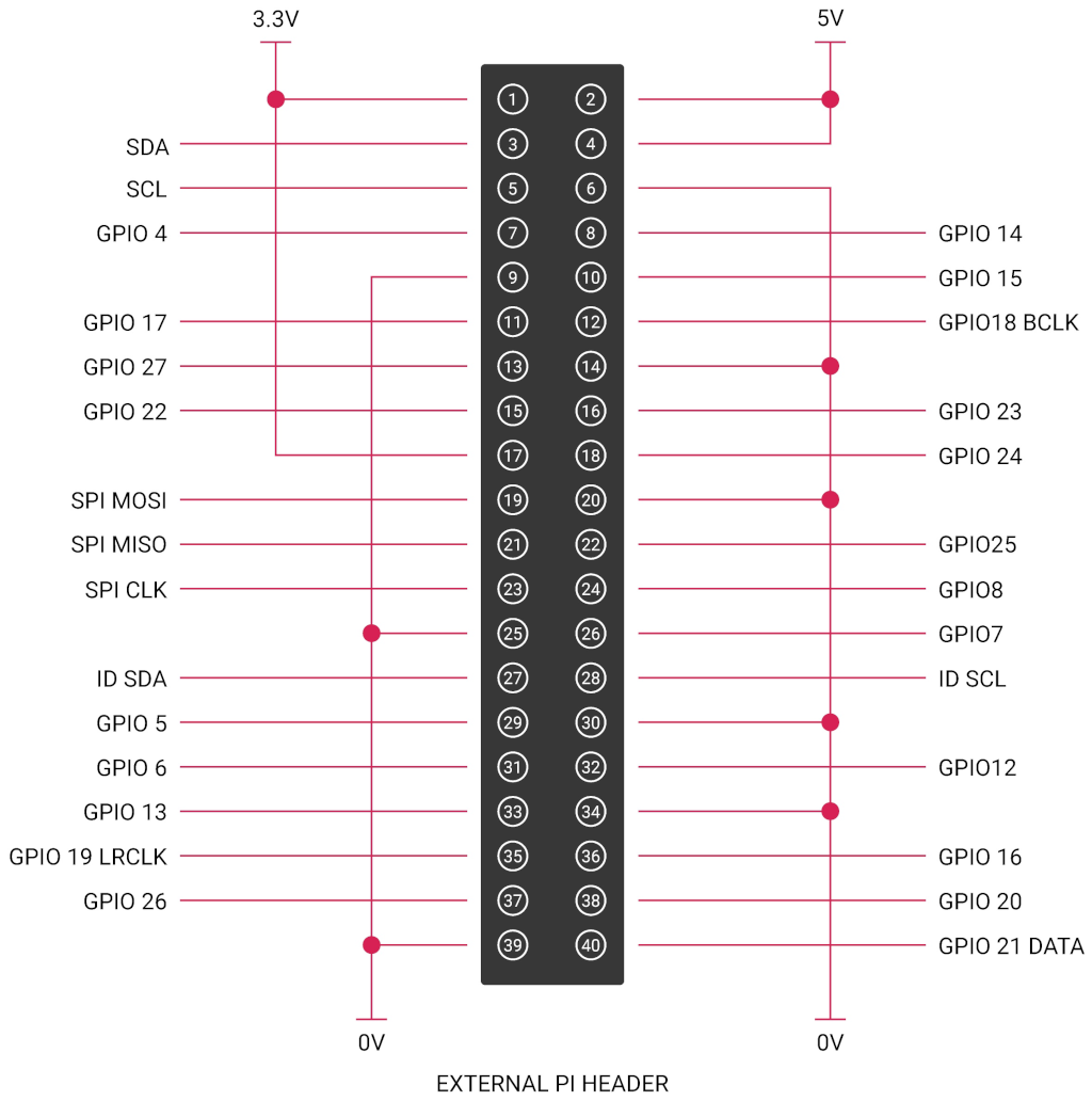
The DAC PRO, DAC+ and DigiAMP+ re-expose the Raspberry Pi signals, allowing additional sensors and peripherals to be added easily. Some signals are for exclusive use (I2S and EEPROM) by some of our boards; others, such as I2C, can be shared across multiple boards.
Saving AlsaMixer settings
To store the AlsaMixer settings, add the following at the command line:
$ sudo alsactl storeYou can save the current state to a file, then reload that state at startup.
To save, run the following command, replacing <username> with your username:
$ sudo alsactl store -f /home/<username>/usecase.stateTo restore a saved file, run the following command, replacing <username> with your username:
$ sudo alsactl restore -f /home/<username>/usecase.stateMPD-based audio with volume control
To allow Music Player Daemon (MPD)-based audio software to control the audio board’s built in volume, you might need to change the file /etc/mpd.conf to support the correct AlsaMixer name.
This can be achieved by ensuring the 'Audio output' section of /etc/mpd.conf has the 'mixer_control'
line. Below is an example for the Texas Instruments-based boards (DAC
PRO/DAC+/DigiAMP+):
audio_output {
    type "alsa"
    name "ALSA Device"
    mixer_control "Digital"
}
Updating your firmware
Edit this on GitHub
Raspberry Pi Audio Boards use an EEPROM that contains information that is used by the host Raspberry Pi device to select the appropriate driver at boot time. This information is programmed into the EEPROM during manufacture. There are some circumstances where the end user might want to update the EEPROM contents: this can be done from the command line.
|
Important
|
Before proceeding, update the version of Raspberry Pi OS running on your Raspberry Pi to the latest version. |
The EEPROM write-protect link
During the programming process you will need to connect the two pads shown in the red box with a wire to pull down the EEPROM write-protect link.

|
Note
|
In some cases, the two pads might already have a 0 Ω resistor fitted to bridge the write-protect link, as illustrated in the picture of the Codec Zero board. |
Program the EEPROM
When the write-protect line has been pulled down, the EEPROM can be programmed.
First install the utilities and then run the programmer. Open up a terminal window and type the following:
$ sudo apt update
$ sudo apt install rpi-audio-utils
$ sudo rpi-audio-flash
After starting, you will see a warning screen.

Select Yes to proceed. You see a menu where you can select your hardware.

|
Note
|
If no HAT is present, or if the connected HAT is not a Raspberry Pi Audio board, you will be presented with an error screen. If the firmware has already been updated on the board, a message will be displayed informing you that you do not have to continue. |
After selecting the hardware, a screen will display while the new firmware is flashed to the HAT.

Afterwards a screen will display telling you that the new firmware has installed.

|
Note
|
If the firmware fails to install correctly, you will see an error screen. Try removing and reseating the HAT, then flash the firmware again. |