Pico microcontroller boards
Raspberry Pi Pico is a development board that uses Raspberry Pi microcontrollers (RP2040 or RP2350). A Raspberry Pi Pico is programmed using MicroPython, C, or C++ and, unlike other Raspberry Pi devices, doesn’t run Linux or support removable storage. Instead, Raspberry Pi Pico is programmed by flashing binaries to the on-board flash memory.
There are two generations of the Raspberry Pi Pico series:
-
Raspberry Pi Pico (Pico 1)
Each generation is available in four variants, which differ based on:
-
Wireless connectivity. Variants that include the W suffix in the name include Wi-Fi and Bluetooth.
-
Presoldered headers. Variants are available either as castellated modules (for direct soldering) or with presoldered pin headers.
Raspberry Pi Pico
Edit this on GitHub
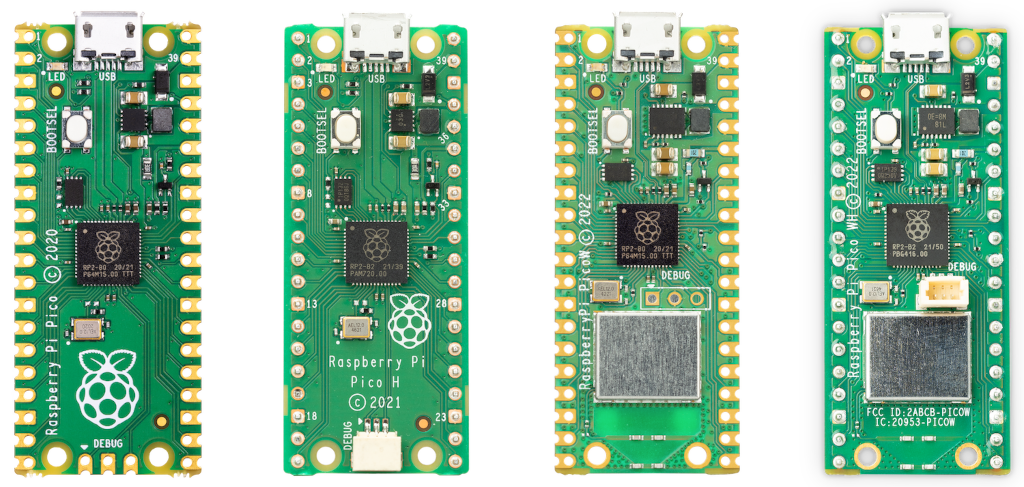
The first generation of Raspberry Pi Pico is based on the RP2040 microcontroller chip. It comes in four variants, listed in Table 1. For more detail about the variants, see Non-wireless Raspberry Pi Pico boards (Raspberry Pi Pico and Pico H) and Wireless Raspberry Pi Pico boards (Raspberry Pi Pico W and Pico WH).
| Wireless | Headers | |
|---|---|---|
Raspberry Pi Pico |
No |
No |
Raspberry Pi Pico H |
No |
Yes (presoldered) |
Raspberry Pi Pico W |
Yes (Wi-Fi and Bluetooth) |
No |
Raspberry Pi Pico WH |
Yes (Wi-Fi and Bluetooth) |
Yes (presoldered) |
Figure 1 provides a visual reference for the four Raspberry Pi Pico variants as seen from the top. Visually, these variants differ most obviously based on:
-
The presence or absence of a wireless component.
-
The presence or absence of presoldered header pins.
-
The location and type of Serial Wire Debug (SWD) interface.
For more information about these differences, see Non-wireless Raspberry Pi Pico boards and Wireless Raspberry Pi Pico boards.
Non-wireless Raspberry Pi Pico boards
Raspberry Pi Pico and Pico H are first-generation, non-wireless microcontroller boards based on the RP2040 chip. Both boards offer identical hardware capabilities, with the only physical differences being the presence of presoldered header pins on Raspberry Pi Pico H, and the style of the debug connector at the bottom of the boards. For more information, see Debug connector (SWD).
The pinout and board layout for Raspberry Pi Pico and Pico H is the same as for Raspberry Pi Pico 2 and Pico 2 with headers. For more information, see Non-wireless board layout.
Key features
Raspberry Pi Pico and Pico H offer the following key features:
-
RP2040 microcontroller chip, including:
-
Dual-core M0+ processor.
-
Flexible clock running up to 133 MHz.
-
264 kB of SRAM.
-
USB 1.1 controller and PHY with device and host support.
-
Low-power sleep and dormant modes.
-
Accurate clock and timer.
-
Accelerated floating-point libraries.
-
Temperature sensor.
-
Eight Programmable I/O (PIO) state machines for custom peripheral support.
-
Flexible, user-programmable high-speed I/O.
-
Can emulate interfaces such as SD card and VGA.
-
-
-
Board features:
-
Drag-and-drop programming using mass storage over USB.
-
2 MB of on-board flash memory.
-
26 multi-function GPIO pins. For more information, see Non-wireless board layout.
-
Debug connector. For more information, see Debug connector (SWD).
-
-
Peripheral interfaces:
-
Two SPI
-
Two I2C
-
Two UART
-
Three 12-bit ADC
-
16 PWM channels
-
Resources for non-wireless Raspberry Pi Pico boards
Raspberry Pi offers additional technical documentation relevant to Raspberry Pi Pico and Pico H:
Additionally, Raspberry Pi provides the following supporting hardware design resources:
-
Design files (Cadence Allegro): PCB design files for studying or reproducing the board layout.
-
STEP file: a 3-dimensional CAD model of the board for enclosure and mechanical design.
-
Fritzing parts: components for use in Fritzing, an electronics design tool for layouts and schematics:
|
Important
|
Design files for Raspberry Pi Pico and Pico H are openly available with no limitations. Raspberry Pi grants permission to use, copy, modify, and distribute the following designs for any purpose, with or without fee. Designs are provided 'as-is' and the author disclaims all warranties with regard to the design, including all implied warranties of merchantability and fitness. In no event shall the author be liable for any special, direct, indirect, or consequential damages or any damages whatsoever resulting from loss of use, data, or profits, whether in an action of contract, negligence, or other tortious action, arising out of or in connection with the use or performance of the design. |
Wireless Raspberry Pi Pico boards
Raspberry Pi Pico W and Pico WH are first-generation, wireless microcontroller boards based on the RP2040 chip. Both boards offer identical hardware capabilities, with the only physical differences being the presence of presoldered header pins on Raspberry Pi Pico WH, and the style of the debug connector below the microcontroller. For more information, see Debug connector (SWD).
The pinout and board layout for Raspberry Pi Pico W and Pico WH is the same as for Raspberry Pi Pico 2 W and Pico 2 W with headers. For more information, see Wireless board layout.
Key features
Raspberry Pi Pico W and Pico WH offer the same key features as Raspberry Pi Pico and Pico H, but with added wireless functionality. Specifically, Raspberry Pi Pico W and Pico WH offer the following key features:
-
RP2040 microcontroller chip, including:
-
Dual-core M0+ processor.
-
Flexible clock running up to 133 MHz.
-
264 kB of SRAM.
-
USB 1.1 controller and PHY with device and host support.
-
Low-power sleep and dormant modes.
-
Accurate clock and timer.
-
Accelerated floating-point libraries.
-
Temperature sensor.
-
Eight Programmable I/O (PIO) state machines for custom peripheral support.
-
Flexible, user-programmable high-speed I/O.
-
Can emulate interfaces such as SD card and VGA.
-
-
-
Board features:
-
Drag-and-drop programming using mass storage over USB.
-
2 MB of on-board flash memory.
-
26 multi-function GPIO pins. For more information, see Wireless board layout.
-
Debug connector. For more information, see Debug connector (SWD).
-
-
Peripheral interfaces:
-
Two SPI
-
Two I2C
-
Two UART
-
Three 12-bit ADC
-
16 PWM channels
-
-
Wireless connectivity:
-
Wi-Fi (802.11n):
-
Single-band (2.4 GHz).
-
WPA3, a modern security protocol for wireless connectivity.
-
Soft access point for broadcasting a Wi-Fi network, supporting up to four clients.
-
-
Bluetooth 5.2:
-
Support for Bluetooth Low Energy (BLE) Central and Peripheral roles.
-
Support for Bluetooth Classic.
-
-
For more information about the wireless hardware and functionality of Raspberry Pi Pico W and Pico WH, see Wireless models.
Resources for wireless Raspberry Pi Pico boards
Raspberry Pi offers additional technical documentation relevant to Raspberry Pi Pico W and Pico WH:
Additionally, Raspberry Pi provides the following supporting hardware design resources:
-
Design files (Cadence Allegro): PCB design files for studying or reproducing the board layout.
-
STEP file: a 3-dimensional CAD model of the board for enclosure and mechanical design.
-
Fritzing part: component for use in Fritzing, an electronics design tool for layouts and schematics: Fritzing part for Raspberry Pi Pico W.
|
Important
|
Design files for Raspberry Pi Pico W and Pico WH are openly available with no limitations. Raspberry Pi grants permission to use, copy, modify, and distribute the following designs for any purpose, with or without fee. Designs are provided 'as-is' and the author disclaims all warranties with regard to the design, including all implied warranties of merchantability and fitness. In no event shall the author be liable for any special, direct, indirect, or consequential damages or any damages whatsoever resulting from loss of use, data, or profits, whether in an action of contract, negligence, or other tortious action, arising out of or in connection with the use or performance of the design. |
Raspberry Pi Pico 2
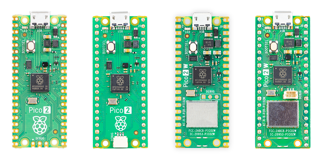
Raspberry Pi Pico 2 is based on the RP2350 microcontroller chip. It comes in four variants, listed in Table 2. Unlike Raspberry Pi Pico H and Pico WH, 'headers' isn’t shortened to 'H'.
| Wireless | Headers | |
|---|---|---|
Raspberry Pi Pico 2 |
No |
No |
Raspberry Pi Pico 2 with headers |
No |
Yes (presoldered) |
Raspberry Pi Pico 2 W |
Yes (Wi-Fi and Bluetooth) |
No |
Raspberry Pi Pico 2 W with headers |
Yes (Wi-Fi and Bluetooth) |
Yes (presoldered) |
Figure 2 provides a visual reference for the four Raspberry Pi Pico 2 variants as seen from the top. Visually, these variants differ most obviously based on:
-
The presence or absence of a wireless component.
-
The presence or absence of presoldered header pins.
-
The location and type of Serial Wire Debug (SWD) interface.
For more information about these differences, see Non-wireless Raspberry Pi Pico 2 boards and Wireless Raspberry Pi Pico 2 boards.
Non-wireless Raspberry Pi Pico 2 boards
Raspberry Pi Pico 2 and Pico 2 with headers are non-wireless microcontroller boards based on the RP2350 chip. Both boards offer identical hardware capabilities, with the only physical differences being the presence of presoldered header pins on Raspberry Pi Pico 2 with headers, and the style of the debug connector at the bottom of the boards. For more information, see Debug connector (SWD).
The pinout and board layout for Raspberry Pi Pico 2 and Pico 2 with headers is the same as for Raspberry Pi Pico and Pico H. For more information, see Non-wireless board layout.
Key features
Raspberry Pi Pico 2 and Pico 2 with headers offer the following key features:
-
RP2350 microcontroller chip, including:
-
A choice of CPU architecture that can run tasks in parallel. For more information, see Architecture switching:
-
Dual-core Arm Cortex-M33.
-
Dual-core Hazard3 RISC-V processor.
-
-
Flexible clock running up to 150 MHz.
-
520 kB of SRAM.
-
USB 1.1 controller and PHY with device and host support.
-
Low-power sleep and dormant modes.
-
Accurate clock and timer.
-
Temperature sensor.
-
Twelve Programmable I/O (PIO) state machines for custom peripheral support.
-
Flexible, user-programmable high-speed I/O.
-
Can emulate interfaces such as SD card and VGA.
-
-
-
Board features:
-
Drag-and-drop programming using mass storage over USB.
-
4 MB of on-board flash memory.
-
26 multi-function GPIO pins. For more information, see Non-wireless board layout.
-
Hardware and software compatibility with Raspberry Pi Pico 1.
-
Two timers with 4 alarms, and an AON timer.
-
Debug connector. For more information, see Debug connector (SWD).
-
-
Peripheral interfaces:
-
Two SPI
-
Two I2C
-
Two UART
-
Three 12-bit ADC
-
16 PWM channels
-
Resources
Raspberry Pi offers additional technical documentation relevant to Raspberry Pi Pico 2 and Pico 2 with headers:
Additionally, Raspberry Pi provides the following supporting hardware design resources:
-
STEP file: a 3-dimensional CAD model of the board for enclosure and mechanical design.
-
Fritzing part: component for use in Fritzing, an electronics design tool for layouts and schematics: Fritzing part for Raspberry Pi Pico 2.
|
Important
|
Design files for Raspberry Pi Pico 2 and Pico 2 with headers are openly available with no limitations. Raspberry Pi grants permission to use, copy, modify, and distribute the following designs for any purpose, with or without fee. Designs are provided 'as-is' and the author disclaims all warranties with regard to the design, including all implied warranties of merchantability and fitness. In no event shall the author be liable for any special, direct, indirect, or consequential damages or any damages whatsoever resulting from loss of use, data, or profits, whether in an action of contract, negligence, or other tortious action, arising out of or in connection with the use or performance of the design. |
Wireless Raspberry Pi Pico 2 boards
Raspberry Pi Pico 2 W and Pico 2 W with headers are wireless microcontroller boards based on the RP2350 chip. Both boards offer identical hardware capabilities, with the only physical differences being the presence of presoldered header pins on Raspberry Pi Pico 2 with headers, and the style of the debug connector below the microcontroller. For more information, see Debug connector (SWD).
The pinout and board layout for Raspberry Pi Pico 2 W and Pico 2 W with headers is the same as for Raspberry Pi Pico W and Pico WH. For more information, see Wireless board layout.
Key features
Raspberry Pi Pico 2 W and Pico 2 W with headers offer the same key features as Raspberry Pi Pico 2 and Pico 2 with headers, but with added wireless functionality. Specifically, Raspberry Pi Pico 2 W and Pico 2 W with headers offer the following key features:
-
RP2350 microcontroller chip, including:
-
A choice of CPU architectures that can run tasks in parallel. For more information, see Architecture switching:
-
Dual-core Arm Cortex-M33.
-
Dual-core Hazard3 RISC-V processor.
-
-
Flexible clock running up to 150 MHz.
-
520 kB of SRAM.
-
USB 1.1 controller and PHY with device and host support.
-
Low-power sleep and dormant modes.
-
Accurate clock and timer.
-
Temperature sensor.
-
Twelve Programmable I/O (PIO) state machines for custom peripheral support.
-
Flexible, user-programmable high-speed I/O.
-
Can emulate interfaces such as SD card and VGA.
-
-
-
Board features:
-
Drag-and-drop programming using mass storage over USB.
-
4 MB of on-board flash memory.
-
26 multi-function GPIO pins. For more information, see Non-wireless board layout.
-
Hardware and software compatibility with Raspberry Pi Pico 1.
-
Two timers with 4 alarms, and an AON timer.
-
Debug connector. For more information, see Debug connector (SWD).
-
-
Peripheral interfaces:
-
Two SPI
-
Two I2C
-
Two UART
-
Three 12-bit ADC
-
16 PWM channels
-
-
Wireless connectivity:
-
Wi-Fi (802.11n):
-
Single-band (2.4 GHz).
-
WPA3, a modern security protocol for wireless connectivity.
-
Soft access point for broadcasting a Wi-Fi network, supporting up to four clients.
-
-
Bluetooth 5.2:
-
Support for Bluetooth Low Energy (BLE) Central and Peripheral roles.
-
Support for Bluetooth Classic.
-
-
For more information about the wireless hardware and functionality of Raspberry Pi Pico 2 W and Pico 2 W with headers, see Wireless models.
Resources for wireless Raspberry Pi Pico 2 boards
Raspberry Pi offers additional technical documentation relevant to Raspberry Pi Pico 2 W and Pico 2 W with headers:
Additionally, Raspberry Pi provides a schematic diagram to support hardware design.
|
Important
|
Design files for Raspberry Pi Pico 2 W and Pico 2 W with headers are openly available with no limitations. Raspberry Pi grants permission to use, copy, modify, and distribute the following designs for any purpose, with or without fee. Designs are provided 'as-is' and the author disclaims all warranties with regard to the design, including all implied warranties of merchantability and fitness. In no event shall the author be liable for any special, direct, indirect, or consequential damages or any damages whatsoever resulting from loss of use, data, or profits, whether in an action of contract, negligence, or other tortious action, arising out of or in connection with the use or performance of the design. |
Wireless models
Wireless Raspberry Pi Pico models (Raspberry Pi Pico W, Pico WH, Pico 2 W, and Pico 2 W with headers) integrate Wi-Fi and Bluetooth connectivity directly into the board, making them suitable for connected and IoT applications, without requiring external radio modules.
Wireless hardware and antenna
Wireless Raspberry Pi Pico models use the Infineon CYW43439 wireless chip, connected to the on-board microcontroller through an SPI interface operating at up to 33 MHz. Wireless Raspberry Pi Pico models also feature an on-board antenna licensed from ABRACON (formerly ProAnt).
Because this wireless subsystem shares some of the pins, some interface signals are multiplexed with other board functions.
-
The SPI clock line (
CLK) is shared with theVSYSvoltage monitor, and so the ADC can only readVSYSwhen no SPI transaction is in progress. -
The Infineon CYW43439
DIN/OUTandIRQsignals share a pin, so you can only check for interrupt requests (IRQ) when no SPI transaction is in progress.
For optimal wireless performance, keep the antenna space free. Placing metal near or under the antenna can significantly reduce signal gain and bandwidth; grounded metal placed along the sides of the antenna can improve the antenna’s bandwidth.
Wireless software licensing
The software libraries, libcyw43 and BTstack, are free to use for non-commercial projects. However, Raspberry Pi has negotiated special commercial rights for Raspberry Pi Pico and microcontroller users. This means that users are granted a free licence for commercial use for projects built with:
-
Wireless Raspberry Pi Pico boards (Raspberry Pi Pico W, Pico WH, Pico 2 W, and Pico 2 W with headers).
-
A combination of RP2040 and CYW43439, or RP2350 and CYW43439.
For the full libcyw43 commercial licence, see cyw43-driver in GitHub. For the full BTstack commercial licence, see pico_btstack in GitHub.
Board layouts
Raspberry Pi Pico boards provide minimal external circuitry to support the microcontroller chip. This section describes the physical layout and pin assignments (pinouts) of Raspberry Pi Pico boards. Non-wireless Raspberry Pi Pico boards share a common layout and pinout, as do wireless Raspberry Pi Pico boards.
Non-wireless board layout
Figure 3 and Figure 4 provide a top-down view of non-wireless Raspberry Pi Pico and Pico 2 boards, including their pinouts. Aside from minor visual differences, the main layout is the same for all non-wireless boards: Raspberry Pico, Pico H, Pico 2, and Pico 2 with headers. The only major visual difference between these non-wireless boards is the presence or absence of presoldered headers, and the exact nature of the SWD interface; for more information, see Debug connector (SWD).


Broadly, a non-wireless Raspberry Pi Pico board is laid out as follows:
-
The Micro USB port for power and data is located at the top edge of the board.
-
The LED (connected to
GP25) is located to the left of the Micro USB port. -
The BOOTSEL button is located under the USB port and to the left side of the board.
-
The microcontroller chip is located near the middle of the board.
-
The DEBUG pads (SWD interface) are located at the bottom edge of the board. For more information, see Debug connector (SWD).
-
40 pins are located on the left and right edges of the board, 20 on each side. For more information, see Pin functions.
Wireless board layout
Figure 5 and Figure 6 provide a top-down view of wireless Raspberry Pi Pico and Pico 2 boards, including their pinouts. Aside from minor visual differences, the main layout is the same for all wireless boards: Raspberry Pico W, Pico WH, Pico 2 W, and Pico 2 W with headers. The only major visual difference between these wireless boards is the presence or absence of presoldered headers, and the exact nature of the SWD interface; for more information, see Debug connector (SWD).


Broadly, a wireless Raspberry Pi Pico board is laid out as follows:
-
The Micro USB port for power and data is located at the top edge of the board.
-
The LED (connected to the wireless chip through
WL_GPIO0) is located to the left of the Micro USB port. -
The BOOTSEL button is located under the USB port and to the left side of the board.
-
The microcontroller chip is located near the middle of the board.
-
The DEBUG pads (SWD interface) are located below the microcontroller and to the right. For more information, see Debug connector (SWD).
-
40 pins are located on the left and right edges of the board, 20 on each side. For more information, see Pin functions.
Pin functions
The majority of the microcontroller pins are brought to the user I/O pins on the left and right edges of the board. Four microcontroller I/O pins are used for internal functions: driving an LED, on-board Switched Mode Power Supply (SMPS) power control, and sensing system voltages. Aside from the ground (GND) pins, the 40 pins on the left and right side of a non-wireless Pico board include:
-
26 GPIO pins with overlapping functions (SPI, I2C, UART, and so on) that can be configured for different project needs.
-
Power pins located in the top-right of the board, including:
-
3V3(OUT)at pin 36 (3.3 V regulated output). -
VSYSat pin 39 (2 V to 5 V system input). -
VBUSat pin 40 (5 V input from USB).
-
-
Special-purpose pins:
-
3V3_ENat pin 37. Pulling this pin to ground turns off the Raspberry Pi Pico. -
ADC_VREFat pin 35. Provides the reference voltage for ADC converters. -
AGNDat pin 33 (also aGNDpin). An analogue ground used to provide noise-free ground for sensors. -
RUNat pin 30. The microcontroller reset pin.
-
Debug connector (SWD)
All Raspberry Pi Pico boards include a three-pin Serial Wire Debug (SWD) header, which is the connector for programming and debugging the built-in microcontroller on the board.
The three-pin connector always carries SWDIO (Serial Wire Debug data), GND (ground), and SWCLK (Serial Wire Debug clock). There’s no power pin on this connector. Your Raspberry Pi Pico board must be powered separately over USB or VSYS.
The connector’s location and type differs depending on the board variant, summarised in Table 3. To compare the visual difference between the SWD headers, see Figure 1 in the introduction for Raspberry Pi Pico and Figure 2 in the introduction for Raspberry Pi Pico 2.
| Location | Type | |
|---|---|---|
Raspberry Pi Pico and Pico 2 |
Bottom edge of the board |
Three castellated through-hole pads |
Raspberry Pi Pico H and Pico 2 with headers |
Bottom edge of the board |
Keyed three-pin connector (JST-style) |
Raspberry Pi Pico W and Pico 2 W |
Central, just below the microcontroller chip |
Three through-hole pads |
Raspberry Pi Pico WH and Pico 2 W with headers |
Central, just below the microcontroller chip |
Keyed three-pin connector (JST-style) |
Debug connector locations
The location of the debug connector depends on whether the board is a non-wireless or wireless variant:
-
On non-wireless variants (Raspberry Pi Pico, Pico H, Pico 2, and Pico 2 with headers), the connector is located at the bottom of the board. For a diagram that shows the location of the debug connector on non-wireless boards, see Non-wireless board layout.
-
On wireless variants (Raspberry Pi Pico W, Pico WH, Pico 2 W, and Pico 2 W with headers), the connector is located underneath the microcontroller chip nearer the middle of the board. For a diagram that shows the location of the debug connector on wireless boards, see Wireless board layout.
Debug connector types
The connector type depends on whether the board has presoldered headers:
-
Boards without presoldered headers (Raspberry Pi Pico, Pico W, Pico 2 and Pico 2 W) use three castellated through-hole pads.
-
Boards with presoldered headers (Raspberry Pi Pico H, Pico WH, Pico 2 with headers, and Pico 2 W with headers) use a small, keyed three-pin connector (JST-style). For information about this connector, see Raspberry Pi 3-pin Debug Connector Specification.
The debug connectors on Raspberry Pi Pico boards with headers fit the Raspberry Pi Debug Probe with no modification. For more information, see Debug Probe.
Software utilities
This section describes software tools and utilities available for Raspberry Pi Pico-series devices, including tools for device inspection, debugging, and flash memory management.
Identify what has been programmed
If you’re unsure about what’s currently programmed on your Raspberry Pi Pico, and the program was built using the Pico C or C++ SDK, the binary typically contains metadata such as the application name and version information.
Use the picotool command-line to extract and display this information. For more information, see our picotool GitHub repository. For full usage instructions, see Getting started with Raspberry Pi Pico-series: C/C++ development with Raspberry Pi Pico-series and other Raspberry Pi microcontroller-based boards.
Debug using a Pico-series device
One Raspberry Pi Pico-series device can be used to debug another by running debugprobe, which enables a Raspberry Pi Pico to function as a USB-to-SWD and UART converter. To install the debugprobe firmware:
-
Download the latest firmware release form the debugprobe GitHub repository:
-
debugprobe_on_pico.uf2for the first generation of Raspberry Pi Pico. -
debugprobe_on_pico2.uf2for Raspberry Pi Pico 2.
-
-
On the Raspberry Pi Pico that you intend to use as a debugger, hold down the BOOTSEL button at the same time as you connect it to your computer. A USB mass storage device named RPI-RP2 (Pico) or RP2350 (Pico 2) appears and is mounted as a volume.
-
Copy the appropriate UF2 file to the mounted volume. The volume automatically ejects after the transfer completes.
-
Wait for the device to reboot. Your device now runs the
debugprobefirmware and you can start using it as a debugger.
For more detailed instructions, see Getting started with Raspberry Pi Pico-series: C/C++ development with Raspberry Pi Pico-series and other Raspberry Pi microcontroller-based boards.
Reset flash memory
BOOTSEL mode resides in read-only memory, inside the microcontroller chip on the Raspberry Pi Pico board; it can’t be re-written. As a result, holding the BOOTSEL button while connecting the board always presents the device as a USB mass storage device, ensuring that the board can’t be permanently bricked through software.
If you want to erase the external flash memory, you can copy a special UF2 file to the Raspberry Pi Pico device while it’s in BOOTSEL mode. For the code to erase the external flash memory, see our pico-examples GitHub repository.
Resources for software development
Raspberry Pi offers additional technical documentation development with Raspberry Pi Pico:
For API-level Doxygen documentation for the Raspberry Pi Pico C/C++ SDK, see Pico C SDK.