Sony, the Pi makers – a post from Pete Lomas
Pete Lomas is a trustee of the Raspberry Pi Foundation, and designed the final hardware that turned into the Raspberry Pi. We’ve had so many questions from you about the manufacturing process that Pete decided to put this post together – he’s been working on it for a couple of months, and we’re very, very grateful. Thanks Pete – and thank you to everybody at the Sony factory!
The basic idea is simple: attach components a PCB with solder to make mechanical and electrically conductive joints, test, and ship.
But how do Sony manage to make 4000 Raspberry Pi Model B’s a day – or more astoundingly, one every 7.5 seconds? On a recent trip to the facility we had a look at how the team at Pencoed actually do it, and some of the technical wizardry and skill they use to make it happen.
The Raspberry Pi design is what is termed double sided SMT and single sided PTH. Translated, this means it has surface mount components (SMT) mounted on both sides of the PCB and through hole (PTH) components just on the top side, with the pins pushing out of the bottom.
The PCBs are actually mounted in a panel (or plaque) of six, christened after Liz’s earlier post a “six-pack of Pis”. This has several functions: first it reduces handling at both bare PCB manufacture and assembly as the PCBs travel together all the way to final test and pack. It also provides an area (waste edge) around the PCBs that the machines use to clamp the panel firmly in place. When you are whacking components down at 5.5 parts per second, you want to avoid vibration. It also allows Sony to get round the fact that some components on the Raspberry Pi come right over the edges. If you look at the design in the photograph you can see there are also small areas of waste laminate between the board. Ideally the designer (i.e. me) wants to avoid this but it is not always possible.

This shows a partially finished six-pack of Pis. The strips with dots on will be broken away to separate out the Pis just before test. The bottom left Pi is being given a quick-process validation test.
The manufacturing line is actually made up of four key processes, bottom SMT, top SMT, PTH, test and pack, but the skill of the Sony team goes much further back than that into production engineering and component procurement.

This is the surface mount line used to build Pis. The front machine (white dome) is the one used to print the solder paste. On the very front of it is a loader that can be filled with PCBs. The line automatically takes them as required.
Ingredients
Sony have strict policy on component procurement, and this ensures that we only get good quality parts. Vendor assessment is rigorous, and we have spent many months trawling through the BOM with Sony and validating any proposed alternatives or substitutes. Remember the issue with the mag-jack we had early days with the factory we were using in China? The Sony team are dedicated to making sure that sort of thing cannot happen.
As well as getting the right parts, they also need them in the right packaging. Everything that is required for surface mount operations has to be on a reel, ideally as large a reel as possible. For some small components that will be 10,000 on a single reel, but these will be used up in just a couple of hours, as there are 42 on each PCB. Every time a reel runs out, the line stops and requires operator intervention, so the larger the better.

Reels of components in stores
To keep the wheels turning, all the machines monitor usage and send requests to the stores themselves for replacements! So by the time they are located and booked out of stores and brought to the line, they arrive just in time before the reel runs out. Empty reels are bar-code scanned off the machine, and the new reel is bar-code scanned back on to eliminate the chance of fitting incorrect components.

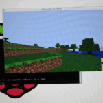
This shows a screen from the system that shows the usage of each component on the machine and when it is due to run out.
Printing the solder paste
The first physical operation is to “paste” the PCB with solder paste. The paste is made up of tiny spheres of solder approximately 25μm across. The other component in the paste is flux. This is designed not only to bind the paste together but also prevents oxidation during the soldering process and is an important aspect of getting a reliable joint.
The machine uses a thin stainless-steel stencil, and the solder paste is pushed through tiny apertures onto the PCB. When the stencil is removed, you are left with tiny prints of solder. On the BGA pads for the BCM2835 these solder prints are only 300μm in diameter. If any of these prints is missing, then a solder joint will not be formed. Just sometimes, rather than the paste sticking to the PCB, it stays in the stencil. To check for this the machine does an optical check immediately after solder paste print just to make sure it is there. If there is a problem, the paste can be removed and the PCB re-printed.

This is a typical solder paste stencil (before anyone posts a comment – no, it’s not a Pi one, but shows the general idea.) These are made of stainless steel and are just 0.004″ thick.

The solder paste can be seen on top of the gold pads on the PCB. On larger areas the paste is cut into segments. This controls the amount of paste more accurately and also provides an escape route for gasses that can build up during reflow as the solvents evaporate.
Once the paste print is verified, the surface mount components can be added to the PCB using a SMT mounting machine. Sony use their own-brand machines, but there are lots to choose from. In principle they all operate the same way, with only subtle differences.
The parts are in “pockets” on each reel of tape, and they are picked out using a vacuum nozzle that is fitted to a moving chunk of mechanics and sensor electronics (the mounting head). The problem is that the parts move around in their little pockets, so the alignment of the part relative to the nozzle is somewhat inaccurate. So, if you place a part straight onto the PCB from the reel, it would be out of line. In modern placement machines this problem is solved using a small camera that looks at the part on the nozzle, figures out its exact location and rotation, and then applies correction factors to ensure that when the part is actually placed it is within 40μm of the optimum position. This accuracy is vitally important when you are placing parts that are only 0.5 by 1.0mm, or if you have tens of tightly spaced legs or pads. When they are running at full speed, these machines can place 25,000 components per hour. When you watch them, they move so quickly that it is almost impossible to see the parts being placed; they just sort of “appear”.

Some tantalum capacitors, on a reel. The pockets that hold the individual components can be seen in the tape. A secondary “cover tape” is peeled off by the machine just before the component is used.
It is difficult to move the mounting head quickly; to stop the larger parts being ripped off the nozzle by inertia the head has to accelerate and decelerate smoothly, and this all takes time. The guys who design these placement machines are real speed demons. To speed things up even further the machines can have up to 12 nozzles, and in some cases two heads working alternately. Whilst one is picking up parts the other is placing then on the PCB, and then the roles reverse.
These dual headed-machines can place at 60,000 components per hour (cph). As it turns out, they are over-specified to help us with Pi, which only has 173 surface-mount components. A 25,000 cph machine with 12 heads is sufficient. Typically, a pack of six Pis has its SMT components mounted in just 150 seconds.
Time to do some baking
Once the parts are placed on the PCBs they have to be soldered. (OK: I could say baked – it is a big oven – but don’t try this at home). The technical term is reflow. What we want to do is heat up the solder (and components) so that the little balls fuse to the component, the PCB and each other.
The reflow oven consists of a number of zones, each one getting progressively hotter until the solder melts (reflows), whereupon the joint is made. The subsequent stages then cool the PCB in a controlled way.
Getting this part of the process wrong can be a recipe for disaster. Too cold, and some of the joints will not form; too quick and the ends of some parts will not heat up evenly, leading to an embarrassing process defect called tombstoning. Too hot, and you fry some of the more delicate components, not to mention the PCB; too slow and the flux burns off before it does it job leaving poor joints: you get the idea.
Again, this is an area where technical skill and years of experience come into play; what the process engineers need to do is find what is called the “process window”, where all the factors are good enough to get reliable joints, and then aim for the ideal point somewhere in the middle. They do this by sacrificing some boards (poor Pi), and adding thermocouple instrumentation to critical parts of the board. These are connected to a mole that follows the PCBs, recording the temperature/time profile for each point. These can then be passed through the reflow oven as many times as is required to get the result. I’ve learnt after explaining this to a group of students that you need to know that the mole is in fact a piece of electronics that is heavily protected against the heat, and not a small furry animal. It took me a few seconds to figure why one of them had a really horrified expression!
Now the parts are solidly attached to the PCB the next step is AOI (Automatic Optical Inspection). Here the PCBs are inspected with a high resolution cameras, and the resulting images processed and compared with images from golden (known good) PCBs. This allows all the parts to be checked for presence, correct rotation, joint soldering and generally anything else that looks odd. Anything that looks out of kilter is then checked by a skilled operator. Sometimes the AOI can be over-fussy and give a false fail, but once I had just a few chips in a reel of 5000 that had whole corner missing, the AOI picked it up in an instant.
All these quality processes are important as it allows Sony to drive down the defect rates to almost unbelievable low levels. They utilise quality principles like Kaizen and lean along with six sigma quality targets. Six sigma is a challenging defect rate of 3.4 faults per million. Unfortunately, that does not mean that only 3.4 Pis in a million will have a problem (in the factory); it relates to everything that could go wrong. These potential problems are termed “Defect Opportunities”. From an assembly point of view, a typical Pi has 100’s opportunities for things to go wrong, like a paste print defect, a missing component or a defective solder joint. The screening and test programs are designed to ensure that these Pis do not leave the manufacturing floor. Even after the Pis have passed everything, there is a quality team checking the final output, effectively checking the quality of the quality processes! The objective is that zero defects reach the customer.

Sony are proud of their quality, and make sure that everyone working the line knows what is being achieved.
PoP on top
So having gotten the underside SMT mounted, the whole process is repeated on the next SMT line for the top-side SMT components. In principle, this is just the same, but the processor and its package-on-package (PoP) memory are mounted on this side and some additional trickery is required.
Once the bulk of the components are mounted on a couple of SMT machines, the panel of boards is passed to a special placement machine that does the PoP. The BCM2835 is placed as any normal part, but the memory has to be placed on top of it. Remember: every surface mount pad that is used on the board to connect a component has had solder paste printed. So how do they get it printed onto the top of the processor? Turns out they don’t: they have a clever little tray full of solder paste in which they dip the memory chip gently, to coat the solder balls on the underside of the part, and then place that (carefully) atop the processor, job done!
I said “clever little tray” as it is constantly rotating and has a scraper bar that sets the exact depth of the paste. Coupled with that there is an automatic dispenser control system that adds more paste as required. It’s really neat, and as expected from Sony, it is the best solution giving phenomenal yields in the volumes required.

The round disk at the front is the tray that contains the solder paste – we will replace this with a short video as soon as we can.
The boards then go further down the line for topside reflow (soldering) and AOI inspection, and the SMT processes are complete. One really good process check is to have a look at joint quality, in particular finish and shape. You can get a hint from inspecting at this point that the process is wandering before it becomes an issue. The joints on the PoP memory package and BGAs are in general difficult to see, but Sony has an optical arrangement that allows an expert to have a look at least at the edges of the package. Any minor problems with shape and alignment can be observed early and adjusted out of the process. Sony also have X-ray facilities to detect bridges and missing solder balls on the underside of all BGA devices.
If you look at the maths, something does not add up. Taking 150 seconds to mount the 147 SMT parts on six Raspberry Pis does not equate to the production rate of one every 7.5 seconds. In fact there are three machines contributing to this figure, one building the underside and two for the topside. This points up another important aspect of efficient manufacture: load balancing. In the whole of the Sony process, the production engineers have ensured that each process step on average takes the same time. If it is too slow, it governs the production rate and they add additional equipment to resolve it.
Final assembly: the PTH components
The through-hole (PTH) parts are actually inserted by hand. On the Pi there are just five. The panel of PCBs are mounted on a solder- and heat-resistant carrier. This shields all the surface-mount components on the underside of the PCB so they don’t get desoldered and end up in the bottom of the solder bath when they are soldered by the wave (flow) soldering machine.

This shows the six pack of Pis with all their through-hole components added, about to be wave soldered.
So, how does this work? As the PCBs enter, the area on the underside is sprayed with flux. This stops the pins, pads and solder oxidising, and ensures a good joint. The PCBs are then (pre) heated. This is important, as it stops the solder cooling too quickly when it comes into contact with the PCB. Further on in the machine, there is a wave of molten solder (hence the name). This is continuously flowing and is pumped out and back into a heated solder pot. The height and shape of the wave and the amount of preheat, the solder pot temperature plus the speed of the PCBs is carefully controlled to ensure a quality joint. It needs skill and judgement to get this exactly right.
If the wave is too tall, it can cause components to be pushed out of the PCB, and in the worst case can cause the top of the board to be flooded with solder. This then resembles a lava flow – yep, I’ve done it! When I asked the guys at Sony about lava accidents, I just got a wry, knowing smile.
End of the line
That’s it: the six-pack of Pis is fully assembled. The Pis are then moved over to the test and packing stations. Here the individual Pis are broken out of the panel and placed on a test unit. Each station has two test units so that one can be used for loading/unloading, whilst the other is used to run the tests and also program the various setup codes such as the model and where it was made.

Here, the operator has two test rigs. One is being unloaded/reloaded while the other is testing a Pi.
A Raspberry Pi that passes the test is placed into its antistatic bag and straight into the box ready for dispatch. Any Pi that fails is going to be pretty lonely: when we were there to take these pictures the “Fail” boxes were empty bar one. That failed unit will be investigated quickly to find out what the problem is, and the defect analysed to see if a process optimisation would help. [Liz interjects: I visited Sony last week, and was told that fewer than 20 Pis have ended up in the “Fail” box since Sony started manufacture. Not bad!]
Making products in this volume also puts stress on the component parameters and the design. With such a number of boards going through, the chances of a group of parts ganging up on the designer to create a “corner case” that causes the Pi to fail test is very real. We work closely with Sony to help identify and correct those where possible. We have already identified a couple of minor tweaks to the PCB that help. For me, even after 30 years in the business, there is always something to learn and the talented team at Sony make great teachers.

The Sony team who make your Raspberry Pi. And some interlopers. Click for bigness.
After Liz, Eben and I met all the team, we can confidently say that the Raspberry Pi is made with tender, loving care in Pencoed. We know: we’ve watched it happen.


101 comments
alex
Fascinating post. Thanks Pete. :) Less than 20 fails is amazing in such a complex process.
Juha
Impressive and interesting, thanks!
But if those 5 through hole components are really inserted by hand, it should not be impossible to omit some of them? I mean, many people have to remove for example the big composite RCA plug and the 3.5 mm headphone jack to make the Pi smaller.
And many of us run Pi as headless, so it would not hurt to remove (=not insert) also HDMI.
How about doing a special headless batch sometime with only ethernet and USB interfaces?
liz
Pete says (by email):
As for leaving stuff off, the cost of a Pi comes partly from them all being the same – the logistical changes to leave these parts off would probably make the boards more expensive. We are currently only planning a Model A variant but we’ll keep your comment in mind.
psergiu
Unsolder them yourself – it’s way easier.
Some people don’t need the HDMI & Composite sockets but need the Audio one. Others need only CSI & Ethernet. An so on. Those are new products, that have to be counted, prices, packed, documented & sold separatelly – this process change will cost a lot and it’s not justified for only about 100 or so of each board configuration that will be built.
Also, i believe that by removing the connectors, the EMI characteristics of the boards change and they will have to be CE EMI tested again.
Andy
In the fourth pic (component usage) it’s a crt monitor – not a flatscreen!
There’s no mention of making the PCBs – does that happen on-site, or does someone else make them?
liz
They’re made offsite in Europe, afaik.
vasi
That’s a Sony!
Just like the old Nokias, these monitor cannot be replaced because they never break!
liz
Pete’s mailed me and asked me to respond for him (I think he’s stuck with some unwieldy mobile device until much later this evening). He says:
If people are interested I’ll do another post on how Pi PCBs are made.
psergiu
Yes, we are :-)
aurelian_15
Yes, it would be great to see how the PCBs are made — I’m especially courious how the multiple layers are “glued” together.
Anyways, thank you very much for this great article!
Robert
Yes, Please! :-)
Andy
Yes please.
Paul Stump
I would like to know about the technologies used today making PCB`s.
(For seven years I worked for Aspocomp, PCB manufacturer. Made “some” PCB´s for next door neighbour Nokia in Salo).
ax25
Would love to know as well as I did some via boards in the past and would live some write up on the multi-layer via boards that you have in the Pi as well. Up to 3 “B” model 1 boards and counting. Having fun putting them all to work and my son awaits the new programmable Minecraft with eager anticipation!
don isenstadt
Just a great article .. I had no idea of what was involved in making one of these .. sort of like an art appreciation class .. thanks for writing it at a level that even I can understand .. :-)
ronster033
This is why I love the RaspberryPI and everything around it. you’re so open in everything and friendly to everyone, even to a lunatic, I just can’t forget the nut job a couple months a go hahaha.
Cheers
solderboy
solder paste pic- R14 ohoh.. lol
liz
Pete says (via email):
No idea why R14 is so funny sorry!
whoops
Solder paste appears to be missing on one of the contacts
Pete Lomas
It’s OK I think – just a trick of the (poor) lighting. Most of the apertures in the solder paste stencil are fractionally smaller in one or both dimensions than the pad itself so that just the right amount of paste is applied. This gives many of the pads a ‘gold fringe’. The solder mask is also slightly larger than the pad and so these show up. On R14, if you look at your board there is a wide track going to a via. It is the gold of this track you can see over the top of the solder paste.
Andrew Joy
That failure rate is only 20 in what over 80 days at 4000 per day, impressive does not do it justice, that Sony plant is amazing.
liz
Not half. I jump at any opportunity to go and visit (we’re back again for some Model A work on Thursday); it’s so slick, and it’s an incredibly good advertisement for the methodologies Sony uses. It’s particularly interesting watching the line change in small details every time we go back; they’re taking the kaizen thing very seriously.
nelson
And a slip of the tongue just revealed that the model A is in production ;)
liz
Not so much – we’ve been talking about it on the forums too! Come and join in. ;)
scruss
They might be six sigma ninjas at the Sony factory, but there’s a glaring language defect in that sign about “One or less common defects”. Countable nouns matter!
liz
Oh, I know – I was actually in two minds about using that picture!
liz
Pete says (via email):
Do you want people with a degree in English or brilliant engineers. Knowing Sony they will raise a non conformance for that :-) That’s why I get Liz to proof everything I write for the foundation – without Liz (and the invisible and brilliant job she does) there would be much more grammatical errors in my stuff, but even Liz cannot stop the odd ‘gotten’ ;-)
[Liz says: I left that “gotten” in there on purpose, ‘cos of what happened last time!]
exartemarte
How about brilliant engineers with an excellent command of English? There probably aren’t enough to go round, but Sony should be able to attract the best. It does matter.
(I nearly picked you up on the “much more grammatical errors”, but I’m hoping that was intentional humour. It was, wasn’t it?)
Pete Lomas
Yes ;-)
Gordon Smith
I’m a Production Engineer, and also have an excellent command of English. I don’t know about being ‘brilliant’ though.
Ken MacIver
Briliant Post;
TIme to give the guys at “How it’s Made” on the Discovery Channel a ring I think.
“How do you make\bake a one piece computer with hundreds of parts too small to handle every 7.5 secs all for $35”
BTW has any maker made Liz a Raspberry Pi Logo shape cookie cutter for her flapjacks yet..
tzj
That would be awesome!
ax25
Seconded on the “hows it made” series. Take a look if you have not ever as it would probably appeal to the younger demographic and could be used in schools to show them where the Rpi boards came from. It would be good history for the future as well.
Ralph Corderoy
An informative post, thanks Pete.
Here the individual Pis are broken out of the panel. Any idea how this happens?
liz
They’re popped out by a machine; Pete will be dropping by later to answer questions, and I’m sure he’ll have more details!
Ralph Corderoy
Ah, I was hoping for something involving the knee of a pretty Welsh maiden à la hand-rolled Cuban cigars. :-)
I can see the fine grid of dots Peter mentions to mark waste areas and what looks like a groove or score line along where the crust of the Pi should be. Perhaps it’s the nature of the PCB that it snaps cleanly?
liz
Well, some of the Welsh maidens involved *are* very pretty (as you can see from the pic) – but they don’t use their knees!
Pete Lomas
Sorry all – I’ve posted later on in this thread with the answers – no knees involved!
liz
Pete says (via email): I’ll look again later.
Gerald Davison
“….the mole is in fact a piece of electronics that is heavily protected against the heat, and not a small furry animal. ”
That made me properly “Laugh Out Loud”….
A fantastic explanation not just of pi production, but generic modern microelectronic assembly.
PaulDow
I’ve got several moles digging through my lawn right now that I would be glad to send over to be used as heat sinks. Just don’t send them back.
I always find this kind of stuff interesting. Even the simplest products usually have some fascinating process behind them. More complicated production is even more amazing.
Riccardo Moretti
Impressive, since one is made in ~7.5 seconds, It got me wondering, how many have been made so far?
and what was the initial Pi sales projection?
liz
I think something over 600,000 have been made so far. We’re expecting to go over a million units by the time we’ve been selling the things for a year – which makes our initial sales projection from 2006 of about 4k boards look a little unenthusiastic!
Riccardo
:-) Love it!a big well done to everyone! Let’s hope the houses that were put up for surety are now secure :-)
Nick
It’s great to see the photos of the assembly process in the UK. I just received my Raspberry Pi Rev 2 board and love it. I was suprised that it was built in China based on the recent posts. Is there any difference between the Rev 2 boards built in the UK and those built in China?
liz
No, there’s no difference. The only distributor making boards in the UK (with Sony) at the moment is Farnell – if you ordered from RS you’ll have got a Chinese board. Farnell are also keeping some line space in China for the eastern hemisphere market, but the vast majority of their boards are now UK ones.
alex
I got a Rev 2 from ModmyPi last week. It had Element14 on the box and Made in China on the Pi. :( It was a little bit disappointing, but that was Pi 3. Pi 4 is sure to be British ;) Still, it survived my attempt to fry it this morning, so can’t complain. :)
Max
How and why did you try to fry your pi? I accidentally fried mine by overvolting it a little too much.
Bertrand (a french canadian)
Really great post! Besides the informative side, this is really (I mean really really) great to see the production of the Pi’s is done locally by skilled people. Makes me very proud to be part in that endeavor.
Tom
What are the orange stickers on the HDMI sockets?
liz
The tape on the HDMI is there to allow the placement machine to pick up the connector. The pickup nozzle uses a vacuum to hold the parts in place. The tape (kapton) covers the slots in the top of the part connector, preventing air leakage.
Tom
So its intended to be removed? I was unsure if it served any purpose on my new Pi.
Allan Sheldon
We take so much for granted in the technological world, but this post spells out some of the otherwise invisible steps taken in getting complex products into our hands. Many thanks for this.
bantammenace
These six-packs of Pi’s and the tiny number of Pi’s reaching the “fail” boxes remind me of my school-days interest in stamp collecting.
The six-pack is the equivalent of a sheet of stamps with gutter pairs. Such a sheet was nearly always worth more than the sum of its parts.
What price a six-pack or a “failed” pi in twenty years time ? These will be the real rarities that will command the high prices.
So if your Pi is doa don’t despair, keep it safe, it may be worth more than a working one in the not too distant future. (btw It doesn’t count if you break it yourself).
vasi
They make sure those don’t ever leave the factories for a good reason :). So if you want one, get employed in the QA/QC dept at Sony, they’ll be all yours.
OTOH, how can you tell if one was DOA or broken by its owner?
liz
Actually, most people are very honest about what they’ve done with a Pi. But we do have ways to tell.
IgorGlock
Really nice pictures from the factory.
:)
liz
If you’d like to see some more, check out the other posts under the Sony tag: http://www.raspberrypi.org/archives/tag/sony
normal
If there aren’t too many confidential processes i would love to see this on “How it’s Made”.
Greg_E
I agree, this would be a great segment.
Leon J Williams
Very interesting and a great post.
Thanks.
Harrkev
I was just wondering how the panel itself it cut to yield six Pis…. A simple saw cannot do this, as some of the connectors hang over the edge. Anything that would cut the boards out would likely chop the edge off of the connectors. The HDMI connector looks particularly vulnerable.
Sandy
I reckon you can see v-score marks running along the long edge of the PIs on the six-pack photo above. If so, the PCB’s would snap apart. Liz mentioned that they’re popped out by a machine… guessing it must somehow apply pressure along the score lines… Maybe we can get a pic? ! Great article! :)
Pete Lomas
The individual Pi boards are held in the panel by only two sides. If you look at the short sides in the photograph, they are completely routed (machined) away. The long sides have been scored. What this means is that 65% of the PCB material is removed by a PCB manufacturing process that cuts two ‘v’ grooves top side and bottom side. Once built the Pis are simply snapped out of the panel using a special tool and careful manual pressure from the operator. If you look at the edges of your Pi you will see that the short edges are very smooth (routed) and the long edges have a slightly rough line halfway through the board. This is the bit that breaks away. This method is very efficient and can be used even where parts overhang the PCB edge.
Ray_GTI-R
Now I understand where the confusion arises when people say traditional PC CPUs are “soldered” to heatsinks, rather than … a heatsink sits on CPUs and requires thermal paste for the best heat transfer between CPU & heatsink. See the many millions of early XBOX remedies.
Solder is solder – it’s a metal. It requires very high heat to melt it. In the outside world us retail customers, solder requires few other words to describe the product e.g., – cored i.e., with flux as an integral constituent, and lead-free – that’s it. It’s normally produced as a wire approx 1mm round or as an un-fluxed stick used by plumbers.
Solder paste is confusing term. Solder paste can be obtained but essentially it’s just roughly ground particles of solder (the metal) in a flux paste. Paint the solder paste on then add heat to form a joint.
Thermal paste or Thermal Interface material (TIM) is just a paste (the Coollaboratory product “Liquid Metal is the only exception that I know of. Tried it … didn’t like it.) where the extremely fine metal content in the paste may be aluminium, silver, gold (I doubt it at today’s prices) etc.
Solder paste requires temperatures around 180 – 190°C* to melt
TIMs require temperatures ranging from almost nothing to 48°C to melt.
HTH, Ray
* I have deliberately avoided reference above to silver solder, a metal available to retail customers as before, at high cost, requires temperatures around 450°C to melt etc since that is mainly used for structural reinforcement e.g., scratch-built slot cars and so on.
Greg_E
That was pretty neat to read, love to see some video of the machines working so I hope you can get some uploaded.
Holger
Funny! They are making 4000 a day?
I think the Raspberry is dead and the whole project fake! Last year in October I was waiting to be able to get a Raspberry PI. One year later, I still haven’t got one.
Hold on, they are producing 4000 a day but its out of stock everywhere? It seems there is no other option then throwing my money into some companues throat to puy myself on a waiting list. Whilst they are playing bank with my money, leaving me clueless when (or ever) I will get one.
Yes I am frustrated and leaves me amazed, why it is so difficult to get a Raspberry PI.
RogerH
In the UK the earliest we could order our Pi’s was February of this year and orders from RS and Farnell have been fulfiled as I have received one from each supplier.
Where did you order your Pi from? Was it from a distributor outside of the UK? Who has taken your money?
JamesH
No Holger, you DID NOT order in October last year because the device did NOT GO ON SALE until February 2012. Since that time over 600,000 have been sold. When did you actually order and who did you order it from? Suggesting the project is a fake is absurd, there are many people out there who have received one – Google will show many many people doing projects with them, or are you suggesting that we are faking thousands of Google results as well?
There was a huge backlog, and 4000 being made a day is making the backlog shorter, but its still there. I suggest checking with whoever you ordered from (you have actually ordered I assume), and checking their posts in the forum.
exartemarte
They certainly exist, though they do seem to have been hard to get in some parts of the world. I live in the UK and I have three; I’m sure I could have a dozen if I’d wanted them. They’re also regularly available on eBay.
Lurch
lol
timofeastiowashire
Great post, Pete. The low error rate is absolutely amazing – this does not happen by accident. Hats off to the entire “Pi” team at Sony. Oh, and yes, I’d love to see a second post the PCB manufacturing process. Thank you!
timofeastiowashire
oh, and video of the machines running – especially the SMT mounting machine taking components off the reels and placing them on the PCBs
Robert
I really dig this kind of “how it’s made” stuff! Now; to do the whole tour on video — I’ll pre-order that DVD :-D
“Here the PCBs are inspected with a high resolution cameras, and the resulting images processed and compared with images from golden (known good) PCBs.”
So….
You’re saying that you need a GoldenEye to verify a true Bond?
:::runs for the exit:::
John
Fascinating. I work in a business school and have just passed on the link to the professor who teaches process management. He will be very interested.
sYED
nICE To kNOW MY pi IS IN goOD HANDS
James Gould
Ahhhhh reminds me of my old days at OMRON, I was the test engineer but got involved with all aspects in the process. I would love to see more on the test side, is there any in circuit testing on the board?
Conrad
Why are are the SMD parts of the bottom side not falling off when baking the 2nd time?
Pete Lomas
For most components it’s the surface tension of the solder that holds them in place. The weight to solder surface area is important, that’s why the SD card socket is actually glued in place as it could fall off.
Conrad
That makes sense, thanks!
exartemarte
I have replaced SD card sockets on two (pre-Sony) Pis and I’m pretty sure neither of those was glued – they seemed to be held by tight fitting pegs in the locating holes.
Pete Lomas
Good spot – I’ve got some glued and some not. If it’s glued you will see two red dots by the mounting points. Sony confirms that they are not needing to glue. Note to self – do not make generalisations based on a sample ;-)
Dean
I wanna 6 pack,
Any chance of getting a few dozen packs together?
I’m sure it’s More than just me that wants an unbroken up 6 pack, for no reason I can quite fathom yet mind!
Vinicius Tinti
Thanks for sharing such a good material.
Ade
Pick and Place is a fascinating process, I work as an embedded software engineer at a small company, but we have a brand new pick and place line to keep manufacturing in house.
We do batches of boards as and when we need to and it’s myself and my boss who run the line, from set up to them coming out of the other side of the board. It’s a far cry from software development, but it’s nice to do every once in a while!
We have a different setup for our solder paste though, we used to use the stencil method but we now have a jet printer which literally prints the paste onto the board like a “bubble jet” printer does. It’s incredibly accurate and although slower it eliminates the need for stencils, which when you’re prototyping many iterations of complex boards would be required for automated assembly. No such problems for us, just create the virtual stencil and away you go!
Another word on AOI is that it’s generally considered good practice to get the first part of processing right (paste + placement), if you get that right then you shouldn’t be seeing any problems at the end. Even with AOI you’re putting a human into the loop and when you’re sitting there for hours seeing pictures flash up on the screen people tend to switch off and press “OK…OK…OK…OK…OK” regardless of whether it is ok.
The machines themselves in operation are mesmerising, have a look on youtube and videos and if you ever get the chance to see one in operation, do it.
Pete Lomas
The interesting thing about printing this way is that you can paste complete rings of solder, with a stencil you need to leave webs to ensure that the middle does not drop out! That said for the volume of Pis, speed is the requirement, so stencil printing is still the way to go.
Ade
Oh for sure, stencil printing takes a constant time of “almost no time” whereas our machine takes a variable amount of time (depending on how much pasting there is) to do a print, it doesn’t matter if it takes 5 minutes to print a complex panel for us because the pick and place will almost certainly take that long – and our machine is 20,000 cph, 8 pickup nozzles on the fast head and also a single mount-head for large items.
We also have control over the amount of paste that gets put down, so we’re not just limited to X, Y & Z being constant (as you would with a stencil) – we can adjust the amount of paste in the Z – which can be useful.
We can also eliminate extra paste on a build basis, so if not much is populated on a particular build we don’t bother pasting those pads.
We obviously have complete control over how a pad is pasted, so we can create all sorts of funky paste shapes for pads!
In mass production stencil will always be king, but in lower volumes and prototyping this equipment kicks ass!
I might be a pick and place bore (and maybe if I did it all day every day I might not find it so interesting!) but I find it mesmerising to watch in action.
node
Great post!
Though, I thought it was a little light on information regarding the manufacturing tests. I work with developing production test systems for electronic products like the Pi myself and I would love to read more about how the Pi is being tested in production! Was the test system developed by Sony or by you guys?
liz
It was developed by Sony – it runs under Arch Linux, because that’s currently the fastest to boot. I’m afraid it’s unlikely we’ll get any more detail out of them on that; it’s proprietary software which is useful for the optimal running of their business, so they’re probably not going to want to release it.
Tim Rowledge
Given the educational nature of the whole Pi project it seems to me that a *lot* more of this kind of post would be welcome and appropriate. How about article sized posts about the process of designing the board and making the first prototypes? Could someone (perhaps from ARM) write about designing the CPU? It might be stretching bit far from the ‘meat’ of the project but it seems like more than a few people would be interested in quite a lot of detail about how things get made.
I imagine there is quite a lot of publicly accessible information already out there but a nicely curated collection of links would fascinating – and of course a little easier than writing it all from scratch.
liz
I recommend a stroll through the archive of this blog; there’s a *lot* about the design process and the first prototypes.
Tim Rowledge
Well that’s a good point. If it could be gathered up into a single, easily linked to place it would be nice. If I can find some time I’ll take that stroll and see if I can make an attempt at connecting it nicely.
reiuyi
A recent EE pitfall is the discovery of how “tin whiskers” are formed over time, due to the usage of leadfree solder. I really do wonder whether the professional electrical production facilities have some counter-measures to prevent tin whiskers from forming.
Anyway, it’s really good to see that Sony cares a lot about producing these products exactly right. Recent years has seen a lot of negative publicity on Sony concerning the so called “Sony Timer”. It’s an urban myth of course, though the legend just won’t die off!
poglad
So what does the red ink blob on/near the “CE” lettering mean? It’s not on my Chinese Pi from RS, but is on the UK ones I got from element14.
Pete Lomas
When the Pi passes test at Sony they add this mark to the PCB.
exartemarte
A very interesting description of both the process and the environment – thank you.
Is Farnell now sourcing exclusively from Sony, or are they also buying elsewhere? It would be nice to be sure that my next Pi will benefit from all that built-in quality. (And help support British jobs.)
AdeV
Excellent and informative post, thanks!
Just one question – PTH I thought meant “Plated Through Hole”, which is a PCB term to ensure the front & back of a 2-sided board (or various layers in a multilayer board) were electrically connected without relying on component legs. Is this now different, and if so what does the “P” of “PTH” stand for?
Pete Lomas
No, nothing new – you are correct – just my abuse of a TLA. I should have sanitised properly. We use PTH to refer to ‘Through Hole’ TH parts, and SMT to refer to Surface Mount parts. Thanks for the comment and I’ll get Liz to edit the post. But don’t get me started on RAM and ROM ;-)
John Lyder
I enjoyed your detailed explanation of the stages in production of the Pi. Thanks for taking the time.
ch0mik
Tantal (from Coltan) – its is from Kongo ?
http://en.wikipedia.org/wiki/Coltan
liz
Sony do not use conflict minerals.
Comments are closed