Controlling Telescopes with Raspberry Pi and Mathematica
Eben: Here’s a guest post from Tom Sherlock, describing how he’s been able to control a telescope using a Raspberry Pi, Mathematica and the Wolfram Language.
As an amateur astronomer, I’m always interested in ways to use Mathematica in my hobby. In earlier blog posts, I’ve written about how Mathematica can be used to process and improve images taken of planets and nebulae. However, I’d like to be able to control my astronomical hardware directly with the Wolfram Language.
In particular, I’ve been curious about using the Wolfram Language as a way to drive my telescope mount, for the purpose of automating an observing session. There is precedent for this because some amateurs use their computerized telescopes to hunt down transient phenomena like supernovas. Software already exists for performing many of the tasks that astronomers engage in—locating objects, managing data, and performing image processing. However, it would be quite cool to automate all the different tasks associated with an observing session from one notebook.
Mathematica is highly useful because it can perform many of these operations in a unified manner. For example, Mathematica incorporates a vast amount of useful astronomical data, including the celestial coordinates of hundreds of thousands of stars, nebula, galaxies, asteroids, and planets. In addition to this, Mathematica‘s image processing and data handling functionality are extremely useful when processing astronomical data.
Previously I’ve done some work interfacing with telescope mounts using an existing library of functions called ASCOM. Although ASCOM is powerful and can drive many devices associated with astronomy, like domes and filter wheels, it is limited because it only works on PCs and needs to be pre-installed on your computer. I wanted to be able to drive my telescope directly from Mathematica running on any platform, and without any special set up.
Telescope Serial Communication Protocols
I did some research and determined that many telescope mounts obey one of two serial protocols for their control: the Meade LX200 protocol and the Celestron NexStar protocol.
The LX200 protocol is used by Meade telescopes like the LX200 series as well as the ETX series. The LX200 protocol is also used by many non-Meade telescope mounts, like those produced by Losmandy and Astro-Physics.
The NexStar protocol is used by Celestron telescopes and mounts as well as those manufactured by its parent company, Synta, including the Orion Atlas/Sirius family of computerized mounts.
The full details of these protocols can be found in the Meade Telescope Serial Command Protocol PDF and the NexStar Communication Protocol PDF.
A notable exception is the Paramount series of telescope mounts from Software Bisque, which use the RTS2 (Remote Telescope System) protocol for remote control of robotic observatories. The RTS2 standard describes communication across a TCP/IP link and isn’t serial-port based. Support for RTS2 will have to be a future project.
Since Mathematica 10 has added direct serial-port support, it’s possible to implement these protocols directly in top-level Wolfram Language code and have the same code drive different mounts from Mathematica running on different platforms, including Linux, Mac, Windows, and Raspberry Pi.
Example: Slewing the Scope
Here’s an example of opening a connection to a telescope mount obeying the LX200 protocol, setting the target and then slewing to that target.
Open the serial port (“/dev/ttyUSB0”) connected to the telescope:
theScope = DeviceOpen["Serial",
{"/dev/ttyUSB0", "BaudRate" -> 9600,
"DataBits" -> 8, "Parity" -> None,
"StopBits" -> 1}];
First we need a simple utility for issuing a command, waiting for a given amount of time (usually a few seconds), and then reading off the single-character response.
ScopeIssueCommand1[theScope_, cmd_String]:=
Module[{},
   DeviceWrite[theScope, cmd];
   Pause[theScopeTimeout];
   FromCharacterCode[DeviceRead[theScope]]
];
These are functions for setting the target right ascension and declination in the LX200 protocol. Here, the right ascension (RA) is specified by a string in the form of HH:MM:SS, and the declination (Dec) by a string in the form of DD:MM:SS.
ScopeSetTargetRightAscension[theScope_,str_String] := ScopeIssueCommand1[theScope,":Sr"<>str<>"#"];

ScopeSetTargetDeclination[theScope_,str_String] := ScopeIssueCommand1[theScope,":Sd"<>str<>"#"];
Now that we have the basics out of the way, in order to slew to a target at coordinates specified by RA and Dec strings, setting the target and then issuing the slew command are combined.
ScopeSlewToRADecPrecise[
   theScope_, ra_String, dec_String]:=
Module[{},
   ScopeSetTargetRightAscension[theScope,ra];
   ScopeSetTargetDeclination[theScope, dec];
   ScopeSlewTargetRADec[theScope]
];
We can also pass in real values as the coordinates, and then convert them to correctly formatted strings for the above function.
ScopeSlewToRADecPrecise[
   theScope_, ra_Real, dec_Real]:=
Module[{rah,ram,ras,rastr,dd,dm,ds,decstr},
   rah=ToString[IntegerPart[ra]];
   ram=ToString[IntegerPart[Abs[FractionalPart[ra]]*60]];
   ras=ToString[IntegerPart[FractionalPart[Abs[
      FractionalPart[ra]]*60]*60]];
   rastr=rah<>":"<>ram<>":"<>ras;
   dd=ToString[IntegerPart[dec]];
   dm=ToString[IntegerPart[Abs[FractionalPart[dec]]*60]];
   ds=ToString[IntegerPart[FractionalPart[Abs[
      FractionalPart[dec]]*60]*60]];
   decstr=dd<>":"<>dm<>":"<>ds;
   ScopeSlewToRADecPrecise[theScope, rastr, decstr]
];
Now we can point the scope to the great globular cluster in Hercules:
ScopeSlewToRADecPrecise[theScope,
AstronomicalData["M13","RightAscension"],
AstronomicalData["M13","Declination"]];
Slew the scope to the Ring Nebula:
ScopeSlewToRADecPrecise[theScope,
NebulaData["M57","RightAscension"],
NebulaData["M57","Declination"]];
And slew the scope to Saturn:
ScopeSlewToRADec[PlanetData["Saturn","RightAscension"],
PlanetData["Saturn","Declination"]];
When the observing session is complete, we can close down the serial connection to the scope.
DeviceClose[theScope];
Please be aware that before trying this on your own scope, you should have limits set up with the mount so that the scope doesn’t accidentally crash into things when slewing around. And of course, no astronomical telescope should be operated during the daytime without a proper solar filter in place.
The previous example works with Mathematica 10 on all supported platforms. The only thing that needs to change is the name of the serial port. For example, on a Windows machine, the port may be called “COM8” or such.
Telescope Control with Raspberry Pi
One interesting platform for telescope control is the Raspberry Pi. This is an inexpensive ($25–$35), low-power-consumption, credit-card-sized computer that runs Linux and is tailor-made for all manner of hackery. Best of all, it comes with a free copy of Mathematica included with the operating system.

Since the Pi is just a Linux box, the Wolfram Language code for serial-port telescope control works on that too. In fact, since the Pi can easily be wirelessly networked, it is possible to connect to it from inside my house, thus solving the number one problem faced by amateur astronomers, namely, how to keep warm when it’s cold outside.
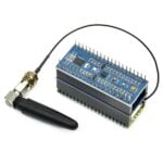
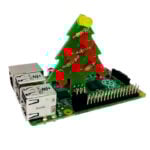
The Pi doesn’t have any direct RS-232 ports in hardware, but an inexpensive USB- to-serial adapter provides a plug-n-play port at /dev/ttyUSB0. In this picture, you can see the small wireless network adapter in the USB socket next to the much larger, blue, usb-to-serial adapter.

Astrophotography with the Pi
Once I had the Pi controlling the telescope, I wondered if I could use it to take pictures through the scope as well. The Raspberry Pi has an inexpensive camera available for $25, which can take reasonably high-resolution images with a wide variety of exposures.

This isn’t as good as a dedicated astronomical camera, because it lacks the active cooling needed to take low-noise images of deep sky objects, but it would be appropriate for capturing images of bright objects like planets, the Moon, or (with proper filtering) the Sun.
It was fairly easy to find the mechanical dimensions of the camera board on the internet, design a telescope adapter…

…and then build the adapter using my lathe and a few pennies worth of acetal resin (Dupont Delrin®) I had in my scrap box. The normal lens on the Pi camera was unscrewed and removed to expose the CCD chip directly because the telescope itself forms the image.

Note that this is a pretty fancy adaptor, and one nearly as good could have been made out of 1 1/4 plumbing parts or an old film canister; this is a place where many people have exercised considerable ingenuity. I bolted the adaptor to the side of the Pi case using some 2-56 screws and insulating stand-offs cut from old spray bottle tubing.

This is how the PiCam looks plugged into the eyepiece port on the back of my telescope, and also plugged into the serial port of my telescope’s mount. In this picture, the PiCam is the transparent plastic box at the center. The other camera with the gray cable at the top is the guiding camera I use when taking long exposure astrophotographs.

Remotely Connecting to the PiCam
The Pi is a Linux box, and it can run vncserver to export its desktop. You can then run a vnc client package, like the free TightVNC, on any other computer that is networked to the Pi. This is a screen shot taken from my Windows PC of the TightVNC application displaying the PiCam’s desktop. Here, the PiCam is running Mathematica and has imported a shot of the Moon’s limb from the camera module attached to the telescope via the adapter described above.

It’s hard to read in the above screen shot, but here is the line I used to import the image from the Pi’s camera module directly into Mathematica:
moonImage=Import[
"!raspistill -ss 1000 -t 10 -w 1024 -h 1024 -o -",
"JPG"]
This command invokes the Pi’s raspistill camera utility and captures a 1024×1024 image exposed at 1,000 microseconds after a 10-second delay, and then brings the resulting JPEG file into Mathematica.
One problem that I haven’t solved is how to easily focus the telescope remotely, because the PiCam’s preview image doesn’t work over the vnc connection. One interesting possibility would be to have Mathematica take a series of exposures while changing the focus via a servo attached to the focus knob of the telescope.
Conclusion
Mathematica and the Wolfram Language provide powerful tools for a wide variety of device control applications. In this case, I’ve used it on several different platforms to control a variety of astronomical hardware.
24 comments
wally
Can’t you just set the focus to infinity and be done with it?
jdb
No – because focus is never guaranteed to be fixed. As you reposition the telescope, the (heavy) main mirror changes and can adjust the focus due to how it rests on its focusing mechanism. Thermal effects (expansion or contraction of the tube) also affect focus.
Richard
how would I connect a potentiometer to control the speed of a d.c. motor using a gertboard and a b+ pi, thanks Richard.
David Palmer
The gertboard has a motor controller. Details on how to use it are in the
manual.
It uses PWM (turning the power on and off rapidly to control how fast it goes) instead of a rheostat (a variable resistor that partially blocks the current flow, but puts a lot of the lost power into heat).
Niall Saunders
As far as focus goes (on a telescope), there is no such thing as ‘infinity’. Remember, we are trying to get objects with very small angular size (pinpoints, like stars – but the same might apply for some item of detail on the Lunar surface) resolved as accurately as possible on the sensor of the attached camera.
Trust me this is no easy task! Many astronomers spend huge amounts of money, and time, trying to maintain accurate focus. Personally, I have been lucky (especially now, with a telescope tube made from Carbon Fibre – which has little dimensional change due to temperature fluctuations) – I can set focus accurately, and not have to refocus for months. But – I am working from inside an observatory (which makes a huge difference).
There are several extremely clever ‘focusing aids’ available – some of which are designed to be used under software control. The Raspberry Pi would certainly lend itself to a ‘closed-loop’ system for those situations where users feel compelled to adjust focus throughout an imaging session.
Cheers,
Niall Saunders
Clinterty Observatories
Aberdeen, UK
Robin Sauls
Could you tell of these “clever focusing” devises.
Tom Sherlock
One simple focusing aid is a Hartmann Mask. This is a disk of cardboard or plywood or plastic that fits over the aperture of the telescope. The mask has 2 or 3 evenly spaced holes arranged at the same radius from the center of the disk. When the scope is out of focus you will see 2 or 3 images for each star (one for each hole). When the scope is in focus, these images will merge to form _one_ image.
A better and more sophisticated mask is called a Bahtinov mask which has a more complex aperture pattern. A Bahtinov mask is good for critical focus. Examples of Bahtinov mask patterns (and generators) can be found on the Internet.
When I focus with my other CCD camera, I first use a Hartmann mask to achieve rough focus and then refine the focus by examining the FWHM (full width at half maximum) value of a star’s central diffraction peak. When this value is minimized, that’s about as good as you can get.
Automating this process using Mathematica and some servos will have to be the subject for a future blog post.
Phil H
With an RPi attached to a telescope and Mathematica, surely the answer to the focusing problem is to take a series of stills and analyse them in Mathematica? The shape of the falloff towards high frequencies in a fourier transform of each image should show a nice progression, from which the maximum can be found.
AndrewS
Yeah, I remember reading that that’s the approach http://openlabtools.eng.cam.ac.uk/Instruments/Microscope/ uses for auto-focus (but using custom code, rather than Mathematica).
Kevin Hainsworth
For those who can’t quite remember where they last put their lathe there may be an alternative: I’m doing this as part of a project to try attach an RPi camera to a bird spotting scope but the same principle may apply to a telescope or microscope or even binoculars (think two cameras and compute module, then think Google Cardboard). Its a bit of an “Aldi four-bird roast” but here goes:
1.srb-photographic.co.uk sell non-dslr digiscoping collars
2.srb-photographic.co.uk sell threaded inserts
3.srb-photographic.co.uk sell empty filter holders
4.plasticdiscs.co.uk sell plastic disks with a hole approx. in the middle.These don’t claim to be precision made so like Goldiliocks I tried 3 of differing disk sizes, each with the same size central hole.
ymmv for what sizes you need so measure everything at least twice.
This may well involve a bit of jiggery-pokery but take your RPi camera and poke it through 4, insert that in 3, attach that to 2 and then 1 and finally attach it to your eyepiece.
Tom Sherlock
I can’t speak for the UK, but here in the States, standard ‘bathroom size’ plumbing drain pipes that would be used on a bathroom sink are conveniently 1 1/4” outside diameter — the same size as a standard eyepiece.
Another alternative would be locating a 35 mm film canister. These are also 1 1/4” in diameter and can be used by cutting off the bottom of the canister and making some appropriately sized holes in the cap for mounting the Pi Camera. I would drill a hole in the exact center of the cap the same size as the outer diameter of the CCD chip assembly. Then I would use this hole to locate the Pi Cam board and use the mounting holes in the board to mark the locations of the screws which will hold it down to the cap.
Niall Saunders
Many moons ago I knocked up a Google SketchUp model of a Pi-Cam ‘Telescope Adapter’ – but I don’t have a 3D printer, and nobody local seems to have one either. I’m happy to publish my efforts to the 3D Warehouse, or to send the file to anyone who has a printer – all I ask for in return is a sample ‘print’. (I’m too much of a cheapskate to pay £30 for someone to print my model commercially – I’d rather use my lathe and milling machine!!)
Cheers,
Niall
AndrewS
Do any telescopes slew fast enough to track the ISS? ;-)
Niall Saunders
Yes, many mounts can easily move fast enough to track the ISS. However, their actual capability to do this often depends on how the mounts can actually be ‘moved’, not whether they can move ‘fast enough’.
Successful solutions have used either a ‘continuous tracking’ motion, or a ‘leap-frog’ approach. Continuous Tracking involves a long series of ‘slew to new position’ commands (sometimes ‘Go To’ commands. Leap-Frog mode usually involves ‘ go to a position, stop, and wait for the target to pass by, then leap forward to the next position, stop, and wait all over again.
Deciding where to start is easy enough = based on readily available information about the orbit of the target (known as ‘ephemeris data’). This also then allows you to know where to ‘go next’ – in order to be there at the right time for the target to pass by.
However, orbit data can be very fickle – the best approach (well-suited to the Pi) is to use a dual telescope setup (sometimes even a triple scope setup) with two cameras (or three) – one on each scope, with each scope providing different levels of magnification of the image. Obviously. all three scopes are fixed together, optically aligned, and share one common mount.
Now the widest field image can be analysed to see if the target can be identified – an a ‘coarse’ guiding command can be issued. If the target then appears in a smaller field of view image – this image can then be used to refine the guiding data. Eventually the fully magnified image can be kept in the most magnified image field – and all the images gathered thereafter are usually streamed into a video format (or are sometimes stacked to create a ‘better’ single frame picture).
It is truly stunning how much detail can actually be seen – the solar panel arrays are usually easily identified, but it was also even possible to see the Space Shuttle docked alongside the main ISS as well.
I hope someone grabs the bull by the horns and starts building and coding (I would love to – I just don’t have the time, but I’m willing to help – and, if you are anywhere local, get in touch with me and you are welcome to come and visit the observatory, day or night).
Cheers,
Niall
Bob Lansdorp
I did exactly this! Tracking ISS with a CG5 mount, webcam guidescope, and custom software, using ASCOM MoveAxis Rate commands. Check it out: http://boblansdorp.blogspot.com/2015/04/iss-with-telescope.html
ucDude
Awesome adapter! A lathe is next on the shopping list.
How did you figure out the correct distance for the camera? I found it hardest to align the camera properly. With your adapter it looks like you are centered on the camera and eyepiece, but how about the distance?
I just finished my work on a soldering microscope. “Similar” setup but different focus length:
DIY Soldering Microscope with HDMI output and 8-25x Zoom.
I really like the live HDMI output feature of the Raspberry Pi. So much simpler than USB and Laptop.
Niall Saunders
Determining where the focal plane of the telescope actually is can be a challenge. It ‘should’ be exactly “the focal distance” from the focal plane of the objective (front) lens (or mirror, etc.). However, determining that point is not easy, because it can be difficult to identify the objective focal plane.
What you can do is to determine where the focal plane of one of you eyepieces lies – by looking through the eyepiece and seeing how far away from a piece of paper it has to be in order for you to see the magnified text (sometimes you will have to unscrew the nose-pice barrel from the lens to be able to try this.
With that distance established, you can also measure back to where the ‘shoulder’ of the eyepiece is (where the eyepiece snugs up against the focuser tube). With those two distances you can then state where the focal plane of the telescope actually is – but only with reference to the focuser tube (which, obviously, cannot be moved at this stage).
The problem is that this focal plane could now either be ‘inside’ the focal tube, or ‘outside’ the focusing tube.
Your Pi-cam adapter has to get the CCD sensor to sit – perfectly square, and centred, at exactly this point.
If the focal plane was outside the focus tube, then either your adapter should provide some means of ‘spacing’ between the camera and the tube, or the focuser must still have enough adjustment to ‘reach out’ to that position – whilst still remaining firm enough to support the camera assembly in a stable manner.
Alternatively, if you need to get the Pi-Cam sensor ‘inside’ the tube, you ‘may’ find that you are able to rack the focus inwards, moving the focus tube ‘out of the way’ whilst getting the sensor to the right location.
Only if you are very, very, lucky will everything be simple. Astroimaging is fun _because_ of the challenges. The reward of a nice-looking image is there to demonstrate that you have actually overcome all the hurdles. The hobby can be likened to running a marathon up a hill, over hurdles, dragging a truck spare tyre behind you, with people throwing rotten fruit at you, on a cold rainy day – and all in the dark!
So, if anyone really wants a lathe to get started – I have a very nice model for sale (I have chosen to upgrade).
Cheers,
Niall Saunders
Clinterty Observatories
Aberdeen, UK
Tom Sherlock
The location of the CCD plane is actually not critical because you are setting the focal point when you focus the telescope. Telescopes like Schmidt-Cassegrain design have considerable back focus and can accommodate some leeway.
As it turned out, I tried to make the camera plane as close to the ‘shoulder’ of the adapter as possible because that is typically where eyepieces have their focal plane and I can do a rough focus by just looking through an eyepiece.
More critical is to get the CCD plane precisely at right angles to the optical axis of the telescope — without that, you won’t be able to get the entire image in focus at the same time. This is where an inexpensive lathe comes in handy because you can create mounting surfaces like this.
BTW, you can do quite a lot with an inexpensive metal lathe (or milling machine) provided you take proper care and don’t exceed the limited capacity of either the tool or the material you are working. My lathe cost less than $300 and I’ve used it to build all manner of devices and engines — you don’t need to have a Hardinge HLV to do this sort of stuff.
Rutger
G’day,
I attached the picam to a lens cap and I use old telelenses. This already gives a huge magnification. Old telelenses can be sourced real cheap as well. I also have the camera to telescope adapter with the thread of my camera so I can (but haven’t yet) use the telescope.
The thing that bothers me though is that I have collected some dust on my sensor since removing the lens and I can’t seem to get the sensor clean anymore.
Does anyone have any suggestions for this?
Thanks in advance,
Rutger.
Awesome piece by the way, way beyond my ‘scope’
Niall Saunders
Hi Rutger,
Cleaning a CCD sensor is not a task for the faint-hearted!!
It takes a little bit of knowledge, a few materials,and a lot of patience.
You will need about 100ml of ‘totally pure’ water (not de-ionised, not distilled, but ‘pure’). Try your local pharmacy, and get a good spectacle cleaning solution whilst you are there, and a very small make-up applicator brush – with a ‘chisel tip’ (or one that can be trimmed to that shape). You will also need a box of “Kl..n.x For Men” tissues (accept no other substitutes).
You might also need about four hour’s free time – and a powerful pair of magnifying eyeglasses. The process involves minimal application of fluid, and good results will only be obtained by repeating the cleaning loop over and over until the sensor becomes truly clean (too detailed to describe here – unless I am asked).
However, many astro-imagers never get their optics truly clean and, instead, opt for ‘post-processing’ their data after acquisition. If you Google for “Flat Field Images Astro”, you would see what I mean.
As I said, you can simply do this on a ‘point-and-shoot’ basis but, hey, you have now got a telescope, controlled by a Pi, feeding photons down the tube to a Pi-Cam. You’ve now already bought a Lathe or a 3D printer – so, why not spend an entire weekend cleaning your sensor better than any surgical instrument!
Of course – when you do all this – you will finally realise what actually controls the weather.
It has nothing to do with Global Warming – it is all the fault of us astronomers (basically all known types of cloud are used in the packaging of all astronomy equipment – and they escape from the cardboard boxes as soon as you open them!!
Cheers,
Niall
Mickey Finn
I’m not sure why it should take as long as four hours? But perhaps you’ve seen some much dirtier optics than I ever have! Cleaning with just water is quite difficult in my experience–the surface tension is high enough that it tends to rip the tissues apart. If you don’t use lint-free tissues (e.g. if you use Kleenex) then there might be problems… these types of tissues also tend to absorb way too much solvent.
Also, glasses cleaning solution is typically not very pure and leaves a soapy mess on whatever it touches.
I’d suggest instead using at least either analytical reagent grade or spectrophotometric grade (99.99% or better) methanol, and Whatman lens tissues. Just fold the tissue up into a small square (wear gloves when handling it!), grip it using surgical forceps, slightly wet it with the methanol (using a Pasteur pipette straight from the packet), and wipe smoothly in one direction only. After each wipe, discard the tissue and use another next time. You can by all means use Milli-Q (“ultra-pure”) water as a supplement to get rid of inorganic residues, but I always prefer to finish with methanol. Cotton buds are, surprisingly, normally not completely awful, provided they’re used with organic solvents rather than water (it wets them too much, leading to disintegration). Commercial cotton is pretty well washed, as it turns out.
As for compressed air–most of those cans are not air but R-134a. This stuff is typically not very pure and has all kinds of greasy stuff dissolved in it, making it a risky material to use. If you don’t have an air compressor with a drying column attached, it’s probably safer to use an air puffer.
Further advice here:
http://www.thorlabs.de/tutorials.cfm?tabID=26066
http://www.edmundoptics.co.uk/technical-resources-center/optics/cleaning-optics
Good luck!
tom munnecke
Astrophotograpers deal with dust on their sensors (and vignetting of the lens as it gets darker to the edges of the frame) by taking “flat frames” and processing them against the star images they take. These are images of the sky at dusk or dawn, or of an evenly illuminated white reflector (the interior of the observatory dome, for example). They also take “dark frames” which are images with the shutter closed to detect bad pixels on the sensors, and the electronic noise of the sensor. Then they use software to remove the noise, and compensate for the flat frame imperfections. Nebulosity is one of the least expensive programs to do this http://www.stark-labs.com/nebulosity.html – I don’t know of any open source approaches. This is a very complicated, but rewarding, form of photography.
David Palmer
If you don’t have a lathe, but do have a 3D printer, I’ve made a printable adaptor here. See the remixes section for a matching Pi case.
ian smith
I destroyed my first pi camera by cleaning it. The bonds are on top and physically cleaning the surface broke some of them.
Perhaps a bottle of air would be a better method. That said, I ruined an ant-reflection coating on a lens once when the bottled air’s propellant squirted onto the lens.
I’m not good at cleaning!
Comments are closed