Upcoming board revision
Update: Added locations of mounting holes. Fixed minor error in I2C paragraph. Clarified expected use of P5 connector.
Update: A lot of people are asking when revision 2.0 boards will appear in the wild. They’ll be filtering out over the next month as the last stocks of the revision 1.0 at each distributor and in each geography are exhausted. I’m aware of at least one person who has received a revision 2.0 board already (from Farnell, in the UK).
We don’t believe that the changes are large enough to make it worth “holding on” for revision 2.0, unless you have a specific requirement to add an audio codec or you need mounting holes for some industrial application.
In the six months since we launched Raspberry Pi, we’ve received a lot of feedback about the original board design. Over the next few weeks, we’ll be gradually rolling out a new revision 2.0 PCB which incorporates some of the most popular suggestions. You can determine which board revision you have by typing cat /proc/cpuinfo at the command line and looking up the hardware revision code in the following table:
| Model and revision | Code(s) |
|---|---|
| Model B Revision 1.0 | 2 |
| Model B Revision 1.0 + ECN0001 (no fuses, D14 removed) | 3 |
| Model B Revision 2.0 | 4, 5, 6 |
There has been a small change to the GPIO pin out of revision 2.0, to add ARM JTAG support and to present a different I2C peripheral from that which is (heavily) used on the camera interface. Users wishing to produce portable GPIO code should either avoid using the these pins, or add code to check the board revision and behave appropriately.
Reset
A reset circuit has been implemented, although in the standard build the required header is not fitted. Users wishing to use this circuit should fit an appropriate header to P6. Shorting P6 pin 1 to P6 pin 2 will cause the BCM2835 to reset.
USB Output Power
The resetable fuses protecting the USB outputs have been removed. This feature was implemented on some later revision 1.0 PCBs by replacing the fuses with links; revision 2.0 permanently implements this modification. It is now possible to reliably power the RPI from a USB hub that back feeds power, but it is important that the chosen hub cannot supply more than 2.5A under fault conditions.
JTAG Debug Support
Two GPIO pins have been interchanged to allow a missing debug signal (ARM_TMS) to appear on P1 pin 13.
Originally the connections were:
- CAM_GPIO [BCM2835/GPIO27] routed to S5 pin 11
- GPIO_GEN2 [BCM2835/GPIO21] routed to P1 pin 13
The new connections are:
- CAM_GPIO [BCM2835/GPIO21] routed to S5 pin 11
- GPIO_GEN2 [BCM2835/GPIO27] routed to P1 pin 13
I2C Support on P1/P6
The primary and secondary I2C channels have been reversed.
Originally the connections were:
- SCL0 [BCM2835/GPIO1] routed to P1 pin 5
- SDA0 [BCM2835/GPIO0] routed to P1 pin 3
- SCL1 [BCM2835/GPIO3] routed to S5 pin 13
- SDA1 [BCM2835/GPIO2] routed to S5 pin 14
The new connections are:
- SCL0 [BCM2835/GPIO1] routed to S5 pin 13
- SDA0 [BCM2835/GPIO0] routed to S5 pin 14
- SCL1 [BCM2835/GPIO3] routed to P1 pin 5
- SDA1 [BCM2835/GPIO2] routed to P1 pin 3
Version Identification Links
The four GPIO signals originally used for version identification have been removed. These were never read by the system software and were redundant.
Additional I/O Expansion
To utilise GPIO signals released by the removal of the version identification links, a new connector site P5 has been added. This carries the four GPIO signals [BCM2835/GPIO28 – BCM2835/GPIO31] named GPIO7 – GPIO10 respectively, along with +5V0, +3V3 and two 0V. Currently this connector is not populated.
This GPIO allocation provides access to one of:
- SDA0, SCL0 (Operating independently of P1 SDA1, SCL1); or
- PCM_CLK, PCM_FS, PCM_DIN, PCM_DOUT or I2S; or
- Four GPIO signals.
This connector is intended to be a suitable attachment point for third-party clock and audio codec boards, and is pinned to be mounted (ideally) on the underside due to connector clash. Pin 1 is marked with the square pad (top left – looking from the top).
+5V0 Leakage from HDMI
Some users have found that connecting an unpowered Raspberry Pi to an HDMI television interferes with the correct operation of CEC for other connected devices. This was fixed on some later revision 1.0 PCBs by removing the ESD protection diode D14; revision 2.0 fixes this issue by connecting the top side of the diode to +5V0_HDMI.
SMSC +1V8
The SMSC 1V8 power has been disconnected from the system supply.
Mounting Holes!
Two 2.5mm (drilled 2.9mm for M2.5 screw) non plated mounting holes have been provided to assist with ATE test mounting. Positions of these holes relative to the bottom left of the PCB (Power Input Corner) are:
- Corner: 0.0mm,0.0mm
- First Mount: 25.5mm,18.0mm
- Second Mount: 80.1mm, 43.6mm
Warning: If used to permanently mount the PCB – do not over tighten screws or drill out to fit larger screws, as this will lead to damage to the PCB.
LED Marking
Two minor changes have been made to the silk screen:
- D9 (Yellow LED) graphic changed from the incorrect 10M to 100
- D5 (Green LED) graphic changed from OK to ACT (Activity)


207 comments
Erik G
If I’ve ordered “1 pcs Raspberry Pi” from one of the shops – and haven’t gotten a shipment sent notification yet – will I be getting a more recent version of the PCB?
Or are they still running the same version in manufacturing?
liz
They’re gradually coming online over the next couple of weeks – so the answer is “maybe”.
LJ
I ordered my board from Farnell and definitely got a UK made new revised version of the board. I’ll take a guess that the turnaround time from manufacturer to sale is refreshingly short! Possibly even ‘Just in Time’ manufacturing?
Tim Eckel
How are people getting their RPI so quickly? I ordered mine on June 29th and have not yet received it! That’s almost 4 months! Yet, others are ordering and getting them right away? Is RS/Allied not a real company and I’ve been scammed out of my cash?
Jake Eskel
I have the same problem… device ordered about April time (for my birthday)… same supplier, and I still don’t have it. They are predicting the end of the year for delivery.
Mex
Can we get side by side photos of the differences?
liz
Yes, but that’s for a later post.
Ozy
Is there any way to pre-order one of the new boards, and be sure we get a new one?
eben
Sadly not – as I mention in the updated post, we don’t think these changes are worth holding on for unless you have a very specific use case in mind.
tzj
like the magpi for example :)
Darren
Will the distributors be clearly marking on their site when the new version is shipping ? as I would like to order another but ensure that it is the new revision.
Andy
Having seen the “pirate” picture, one mounting hole is where TP1 was.
As that was 5V, have we lost that test point (not good) or is the hole at 5V (worse)?
eben
Both holes are at ground. Would make for an entertaining experience if you bolted both to a conductive baseplate otherwise :)
JBeale
“non plated mounting holes” – how can it be at ground if it is non-plated?
eben
Ah yes, my bad. Looking at the board carefully, I can see they’re actually isolated.
Andy
Yes!
So we’ll have to tell people to measure their 5v somewhere else
mahjongg
No, TP1 still exists, it only has been moved slightly to the left.
jojopi
I do not see it. Are you looking at the hole that aligns the SD holder?
TP1 has never been essential, however. An obvious place to look for 5V is the top pad of C6. And if you want a nice plated hole, we are told there is a 5V in the new unpopulated GPIO/I2S/PCM block.
mahjongg
“I do not see it. Are you looking at the hole that aligns the SD holder?”
No its there, but on the published picture it is hidden behind C6. Its a few mm below the alignment hole fo the SD-card holder.
And yes, I do own one, got it yesterday from Farnell.
Andy
Ah, yes.
Now we need you to tell us what the two holes below C11 do
Frapé
I’m just a layman, so please enlighten me ;o) – doesn’t this cause incompatibility to already existing add on (eg Gertboard) boards?
Thanks in advance!
liz
No, it doesn’t.
Jason Railton
I think it sort-of casts a shadow over Gert’s suggestion from ages ago that the easiest way to connect a simple input microswitch is between pin 3 and ground (because of its always-connected pull-up resistor), though technically he did say GPIO_0 and ground, which is still true – it’s just that GPIO_0 is now on pin 14, not 3.
I assume this means that pins 13 & 14 are now the ones with permanent pull-up resistors?
Mike Cook
it’s just that GPIO_0 is now on pin 14, not 3.
No it is not. Pin 14 is a do not connect like it has always been. Pin 3 is now GPIO 2
Peter Mount
Is there any timescale on when these will be available from RS etc? i.e. when released then will they be manufacturing to the new spec?
At some point I’m thinking of getting another pi, the 2 existing ones are in use but use existing case designs but the mounting holes would be of use as it’s going to need a custom case – it’s going to be running a radio telescope alongside several arduinos hence the custom case requirement?
If it’s going to be a couple of months then fine – it’s just would be nice to know when they are shipping the newer revisions
eben
We expect they’ll be filtering out over the next month as the last stocks of the older design at each distributor and in each geography are exhausted. I’m aware of at least one person who has received a revision 2.0 board already (from Farnell, in the UK).
liz
And I’m aware of one in Germany from Farnell too.
Josh
And (apparently) mine in Dubai claims Revision 2. Ordered from Farnell in March, received in late May.
Kevin
I ordered a Raspberry Pi from Farnell on 30/8/12 and received a version 2 board yesterday. Which surprised me as it was showing out of stock when I placed the order.
Comparing it to my older board from RS I’d noticed the P5 pads and had been trying to find out what they were.
Somehow I completely failed to notice the mounting holes until I read your post!
Declan Malone
I have also received a 2.0 (Revision 4 according to /proc/cpuinfo) board from Farnell. I got it 3 days ago via farnell’s .ie site.
Andy
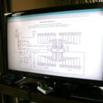
Will a new version of the schematics pdf be available in the near future?
liz
Yes.
Andy
Thanx!
Michael
when will the new schematics will be available? today i recived the new rev board.
Chris Evans
Will any of the changes affect fitting the Pi into the many styles of cases?
eben
No – we’ve been careful to leave the connectors in exactly the same place on the new revision.
Dave
So the USB still sticks out over the board further than the LAN?
Doug
Or the LAN does not stick out as far as the USB? There looks like room to move the RJ45 out to match the USB…
Madhu
Will there be any changes to RAM and CPU, GPU specifics?
liz
This is just a change to the PCB design. All the changes in rev2 are listed in this post (and don’t affect the PoP).
Ozy
I may be jumping the gun, but are there any plans for GPU, CPU, or RAM updates in the pipeline? I’m just curious to see what’s coming.
JamesH
Not at present.
liz
Not at the moment, no.
Geoff
Rather than change the current boards, would there be any sense in a “Model C” with a higher spec (and higher price tag), or would that just divert the team’s attention to unnecessary issues?
I would certainly be interested in a board with more RAM (say 1GB), gigabit Ethernet and a SATA interface or two. The question is whether you could get the volumes on a board like that, and whether that kind of board would cannibalise the sales volumes of the current board, killing the economies of scale which are currently being reached.
Dana
Geoff – Don’t forget about USB3.0
mittfh
I expect the internal answer will be along the lines of “when it’s possible to add them and still achieve the $35 price point.”
Of course, as with the 512MB RAM upgrade, we’ll only be notified once the upgrades are ready to ship (so they don’t have oodles of people cancelling their orders in advance of the new release, resulting in a bunch of unsellable old revision boards).
JBeale
Are any of the GPIO pins labelled on the silkscreen? With the changes already shipping, I anticipate some confusion when people use a Rev-2 board expecting a Rev-1 GPIO pinout as described eg. at the wiki http://elinux.org/Rpi_Low-level_peripherals#Introduction
biker
Thanks eben :D do you have an aprox of when will it be available? (:
biker
sorry,., I hadn’t refresh the page since some time,., so I didn’t see the previous comments,., sorry for the post :P
thanks for the amazing job!
JamesH
Please read the article and the posts above!
Hans Harder
Can your provide the exact location/diameter of the mounting holes on the pcb.
That way I can adapt my case with the correct support…
Andre
Thank you for fixing these (minor) bugs! A new HW revision was of course the right choice.
But as a newbie to low-level electronics etc. I’m in the same boat as Frapé.
To me this all sounds like “Everything regarding the GPIO, and some voltage related stuff etc. is now completely different! Watch out!”.
Doesn’t this totally break compatibility with most self-made HW addons, and the corresponding code and thousands of postings, wiki entries, HowTos etc all over the net?
Is the community now basicly split in half, so that there will be HW/SW for specific revisions?
Will we see more projects with warnings that go like “only tested with Rev. 1!!! If you have Rev. 2 you are on your own! Patch it yourself or whatever. I don’t care.”
Do (less experienced) people now have to look twice and tripple before doing anything, or they will fry their RasPis or connected HW?
Please say something that makes all these worries go away! :-)
eben
Let me try. Firstly, nothing relevant to the user has changed on the voltage side: this is just housekeeping. Tutorials which rely on the particular I2C exposed on the GPIO will need to be updated to query the board revision number: this was a hard decision, but it will significantly improve the usability of the board for the small number of people who want to do both camera and high-rate I2C, and allow kernel-mode non-intrusive debug. Doing this check is pretty trivial, and we will be encouraging (e.g.) Adafruit to take this approach in their tutorials.
We’re confident this is the only time we will have to make this sort of change.
Janet
Haha. Sure it will…
Andre
So, if it all just boils down to this, than it doesn’t sound so scary afterall. I also re-read the article, and think I might have overreacted a little bit. Thanks for clearing things up!
Chris
Can’t wait to get a jtag going :)
DAve Shillito
To look at it another way…
This sort of thing (checking the the version of installed libraries, or operating system) and possibly implementing workarounds is something that you have to do all the time in software engineering.
You may as well get used to it now. ;o)
MORA
For my use I had to change a few lines of code when swapping the board, because of the new GPIO name.
No hardware changes was needed, so IMO this was an acceptable minor change :)
And since /proc/cpuinfo informs you what type of hardware you have, you can actually make a software that works with both revisions.
Peter
All the changes sound great but mounting holes, yippee!
JBeale
The original GPIO connector had five pins labelled “do not connect” to provide for possible future additional I/O connections. Now that the 4 new I/O nets actually go to a separate connector, does that mean we can rely on the “DNC” pins on P1 being connected to ground?
eben
Yes (note – 5V and 3V3 for some of the pins).
JBeale
So to be specific, I gather we may now rely on these P1 GPIO pins to remain as shown in the Rev1 schematic.
P1-04: +5V0, P1-09: GND, P1-14: GND, P1-17: +3V3, P1-20: GND, P1-25: GND. We should update the wiki to that effect.
Marc
Mounting holes – – – -Great.
JTAG pinouts – – – – SUPER!!!
What pins should one look at, and is JTAG possible on a rev 1 board?
eben
It may be possible to do JTAG on a rev 1 board by soldering a flying lead from the camera connector to bring in the missing signal. We’ll have to see if someone figures out how to do this.
asb
https://github.com/dwelch67/raspberrypi/tree/master/armjtag :)
Marc
@ ASB, thanks for the pointer.
John Zajdler
Looks like there is a typo error; Original connection,
◾SCL1 [BCM2835/GPIO3] routed to S1 pin 13
◾SDA1 [BCM2835/GPIO2] routed to S1 pin 14
should say S5 not S1, please confirm.
d3fault
…. any word on Model A? B’s stealing the show! You need to launch Model A so your site’s title isn’t lying ;-)
JamesH
Don’t worry – Model A are still very high up on the list of stuff to do!
eben
Stay patient. Perhaps I’ll update the table in a bit with the (already allocated) Model A codes.
coppermine
All this is nice. What I am concerned about are all those external boards (break-out, header ribbons etc) that will now be deprecated. Am I wrong?
Gordon Henderson
From what I can see, the boards will be fine, but the code using some of the GPIO signals may need changing.
-Gordon
Ben23
“Originally the connections were:
CAM_GPIO [BCM2835/GPIO27] routed to S5 pin 11
GPIO_GEN2 [BCM2835/GPIO21] routed to P1 pin 13
The new connections are:
CAM_GPIO [BCM2835/GPIO21] routed to S5 pin 11
GPIO_GEN2 [BCM2835/GPIO27] routed to P1 pin 13”
The BCM GPIO numbers have been reversed, but shouldn’t the CAM_GPIO and GPIO_GEN2 be the other way round too?
eben
No – CAM_GPIO and GPIO_GEN2 are signal names on our PCB. What you’re seeing above is that we’ve adjusted the Broadcom pin names (BCM2835/GPIOxx) that these lines connect to.
Nial
Another vote for schematics so we can work out what’s going on ourselves? :-)
liz
You don’t need to vote for it – we’ll be publishing them shortly.
NickT
The mounting holes are a definite improvement but not ideal from a placement point of view. Are there plans for future revisions to have have them in more conventional places, like the corners of the board? One small additional question, does this new revision have the tank capacitor mounted in through holes?
liz
No plans to move them. They are where they are, and they won’t be budging. In a board this small where space is constrained, you put ’em where you’ve got space!
C6 is still surface-mount.
Gordon Henderson
OK! I’ve updated wiringPi and I’ll push a new revision as soon as I’ve done some more testing – the upshot is that anyone using wiringPi’s own “pin” numbering scheme won’t be affected as long as they install the new wiringPi and re-link their application.
Any programs using the “traditional” GPIO pin numbers will need to be changed if they used the GPIO pin 0 & 1 (I2C) and third general purpose GPIO pin – aka BCM_GPIO 21 – they’ll now need to change that to 27.
I suspect that one will affect a lot of people (more than the I2C pins changing), so a lot of code will need changing for people who’re using that particular pin.
So stick to wiringPi pin numbers ;-)
-Gordon
texy
….so Gadgetoid will need to update the python wrapped version again ;-)
Texy
bantammenace
Will there now be two versions of Eben’s book ?
Andy
Revision 2 will have mounting holes
Arsham Skrenes
I was hoping that we could have a switch on the board that would allow us to chose between using Power over Ethernet (PoE) or USB to power the RPi. Could this be added to the board in a subsequent revision?
I would like to have several Raspberry Pi’s around my house doing video surveillance and other tasks, and I wanted them to be plugged into ethernet with PoE powered by an uninterrupted power supply (UPS).
eben
The Foundation isn’t currently planning to support PoE, but when we open-source the design, we expect PoE-enabled variants to hit the market pretty quickly.
Kendall Baker
If you really want PoE, I would suggest some PoE injector adapters from amazon or eBay. Such as http://www.ebay.com/itm/PoE-Power-Over-Ethernet-Injector-Splitter-Cable-Adapter-Kit-/150804586719?pt=LH_DefaultDomain_0&hash=item231ca760df
Martyn Jones
So how will the PiFace be affected – will we need to have different programs to control the outputs and read the inputs if we have two versions of the RPi board?
eben
Software intended to work on both board versions will need to read the board id and conditionalize its access to the GPIO lines. If there is enough demand, we may implement a transparent translation in the kernel drivers, at which point the only applications affected will be those which directly map and poke the GPIO registers from userland.
Gordon Henderson
Those who use the “standard” /sys/class/gpio will be affected as gpio21 is now gpio27 – that’s going to be the main issue and while the kernel drivers could swap them over, I think it would just cause even more confusion – what kernel version, what board version, etc….
Just live with it … or use wiringPi ;-)
-Gordon
Gordon Henderson
The PiFace is SPI – won’t be affected at all.
-Gordon
Martyn Jones
Phew!
Gwyn
Is it the same green, or is the new revision in a deeper avocado? I may hold out for avocado…
Tom Gidden
I’m hoping the Model B silkscreen changes from white to yellow on the fourth revision, like its namesake.
liz
We don’t expect there to *be* a fourth revision, happily! There will be a third, but at that point I think we will consider the platform “finished”.
Riccardo
Thanks for the HDMI CEC fix,
Is it possible to modify a Rev 1 board to fix the cec problem?
dom
I’d suggest you remove it, if it causes a problem:
http://www.raspberrypi.org/phpBB3/viewtopic.php?f=35&t=14273
JBeale
Is there any plan to test the rev.2 board for RFI emissions to CE/FCC Class B (Residential) instead of Class A (Commercial) ? http://en.wikipedia.org/wiki/Title_47_CFR_Part_15#Subjects
eben
Not on this version. This will have to wait for the “educational release” board.
ssmith
Liz said “Happily, we’ve found it doesn’t need a shielded enclosure to reach Class B, although it will require a (very minimal) redesign.” Were any of those changes made in this revision?
Gordon Henderson
Is there any definitive way to read the revision? I’ve just seen someone with a revision of: 1000002 and not the 0002 I was expecting…
-Gordon
Gordon Henderson
I’ll reply to myself as I’ve worked it out – it’s the overvolt bit!
-Gordon
Mikael
Yay i2s :-)
Gotta order myself another pie.
kasbah
I too wish there was a way to tell which revision I will get. I want to design a pi-plate using I2S.
I am an in the UK and would order through Farnell. Their lead time is currently 3-weeks, does that mean they are awaiting a delivery of the new revision boards? Given that they have already delivered one rev2, if I order now there is a good change it will be a second revision?
Brian
I ordered a one from Farnell on 03/09/12 and it said there was a 3 week wait. In my impatience I bought one off ebay as 3 weeks seems like an eternity for a new toy only to get an email from Farnell on 05/09/12 saying my order had been desptached.
Dylan
3 weeks? You’re lucky — I ordered one from RS online in June, at the end of August I got an email saying there would be a 9 week delay! I now assume this has something to do with the revisions. Luckily (do far), the Pi is for my Daughter’s birthday in October but I had hoped to get up to speed with it over the the summer, but 9 weeks from August 28 is cutting it awfully close.
JamesH
Nothing to do with revisions. I’d suggest reordering from Farnell, that should be much quicker.
Marc
I also ordered at the end of june, and apparently had the order held up by my ordering a case at the same time. I have heard nothing from RS, except that my payment was made on June 26. Presumably when RS gets arround to fullfillment of the RPI and case, they will now be shipping Rev. 02.
Louis Schreurs
In the not so recent past I had to decide to order predominantly from Farnell for industrial need of parts……….
Brian
Might be worth making an order with Farnell it’s a few quid more than RS but I was willing to pay the extra for quicker delivery as RS was saying 9 weeks. I’ll let you know when mine turns up and what version it is. If you get stuck I have a new sealed one coming from ebay that I might be willing to part with.
Brian
Got mine from Farnell today and it was the new Revision 2 board.
kasbah
Well, I ordered mine Tuesday and got it today. It’s a rev 1 though. I really need a rev 2 as what I want to do requires I2S so I will have to return it and wait.
lingon
It’s nice with the board bugfixes and improvements! Are all the changes
listed here concerning the “Model B Revision 2.0 4”?
What changes are planned for the versions 5 and 6?
Could the SD-reader 1,8 V voltage needed for UHS-I speeds be provided
with a future board revision? Swap space would definitively benefit from
UHS-I speed from the SD-card. Obviously random access write performance
is very important as well as well as the maximum bandwidth.
Joe Miller
So I haven’t seen anyone here ask this but if I would like to get the rev2 board but I already have a rev1 will there be any way to trade it in sometime in the future?
Matt Hawkins
I think the mechanism for “trading it in” is going to be selling it on eBay. Might be best to sell it now while there is still a delay in delivery … and then wait for a Rev2.
Ian
“We don’t believe that the changes are large enough to make it worth “holding on” for revision 2.0, unless you have a specific requirement to add an audio codec or you need mounting holes for some industrial application.”
Could you please expand on “add an audio codec”
Will revision 1 of the boards not be able to add audio codecs (I’m guessing hardware decode, like the MPEG2 and VC1 codecs recently announced)?
mahjongg
You are mixing up software coder decoders (codec), and hardware coder decoders, (also called codec’s) yes I know its confusing!
A software codec takes an encoded stream and decodes it (or vice-versa), a hardware codec is a chip that converts a diigital signal (in this case an I2S signal) and converts it to analog sound signals (and vice-versa)
The new board brings all the signals needed for an I2S interface for a codec chip together on one new GPIO header. The signals are also available on the older board but took some precision soldering of wires to the board.
With an I2S codec you can create high quality audio out and and also audio in (a feature that was missing, you might have a need for it example for skype) it can also provide for optical out, and surround
paulie
MJ, any news on any sound I/o expansion being developed for the new p5 connector?
I have tried to use a USB (cmedia?) Soundcard to run ‘soundmodem’ (for ax25 packet), and both have stopped working – not visible in ‘lsusb’.
So off to pcworld to complain,i think…..
Patrick
Yay for removing the USB fuses!
The worst problem I’ve had with the Pi has been USB devices that fail to work, even if my main supply could provide plenty of power. I altered my Pi to bridge the fuses, now it works great with a webcam in one port and a Wifi stick in the other.
So glad this was changed in the new revision!
Malcolm
So if you are adding JTAG Debug Support is there any chance of getting a public release of a BSDL model for the BCM2835 from Broadcom to enable us to play with Boundry Scan / JTAG?
Tom
Does this mean my rare version 1 Rasp Pi is now worth top dollars?
Also, when will we able to order the updated one? (just kidding, I saw you answered this question about 10 times ;))
Mark
Only if you still have the original box!
peter mulholland
Just got my Raspberry Pi today from Farnell, and it is indeed a rev 2 board – which I’m happy about because I wanted the i2s outputs for a DAC :)
David Lang
This may be a silly thought, but if HDMI has +5v is there any way (including a hack) to power the Pi from it?
I’m looking at a self-contained application where the Pi will have power, network and video, but nothing on USB. If there was some way to eliminate the power connection it would be _really_ handy.
RaTTuS
no the Amp though the hdmi are way too small
Lob0426
Here I have been working away modifying my RasPi to make it Back-power, testing it for around a month, and you just up and change the PCB so it will do it out of the box. Thats just not Right! Quit reading thew dang post in your own forum! ;)
lmao
Josh
I don’t know about others, or when this revision was released to manufacturing, but check your boards. I’ve had mine for 3 months, and it claims to be revision 2.
To the foundation folks:
Can we get some images highlighting the physical changes on the board or a method of physically checking the board, so that we can check the validity of the /proc/cpuinfo file?
Mine was a pretty early shipping board, so I was surprised to see it show revision 2.
I’m also curious if every Revision 2 board should have all the changes, or if some might not. I.E. mine does not have mounting holes, but claims to be revision 2.
Thanks for your time.
Sander
My old, thus first generation Raspi says in /proc/cpuinfo:
“Revision : 0002”
And yes it’s tempting to think this is a Revision 2, but I now understand that in Eben’s table the table header “code(s)” has to be interpreted as “code reported by /proc/cpuinfo under the confusing name ‘Revision’.” … Pffew.
So, as I understand it now: there is a “Raspi model revision” and a “/proc/cpuinfo Revision” , and those numbers do not correspond 1-on-1. Attempt:
“Raspi model revision” “/proc/cpuinfo Revision”
Raspi B 1 2
Raspi B 1 + ECN 3
Raspi B 2 4,5,6
HTH
Sander
Ah, great, the space are gone in my table. Another attempt:
RaspiB-rev1 —– cpu-info-rev2
RaspiB-rev1+ECN —– cpu-info-rev3
RaspiB-rev2 —– cpu-info-rev4,5,6
Sander
PS: Another way to see the difference:
Revision “2.0” (=raspi version) versus Revision “2” (=cpuinfo). So: dots or not dots.
Roger Jönsson
What is needed to get the sound (stereo) output routed through the i2S port?
Lars
Oh, I got my shipping confirmation yesterday. It makes me sad to read what I won’t get in my pi :-(
AndrewS
I guess the “I2C Support on P1/P6” heading in your blog post should actually say “I2C Support on P1/S5”?
Now that the USB output fuses have been removed, has there been any change at the MicroUSB power-input/fuse side? i.e. if powering a new Rev2 board via the MicroUSB port (and a suitably powerful PSU) is it possible to get the full 500mA from each USB port?
murmel
Yet another JTAG connecter?
I’m out of electronics for a while – but isn’t there a thing called “JTAG-CHAIN” in the IEEE-Standard 1149.1, where ONE connector on the board can be used to accesses multiple devices?
This could probably free space and connectors for additional useful Features (GPIOs, Mounting holes, etc. ). – Probably too late now, but maybe to be put on the list.
cheers murmel!
mahjongg
JTAG Chaining is technically possible, but slows down the scanning process a lot, and that might be undesirable.
Irgendwer
A nice improvement IMHO could also consist in a variant change of the connectors.
ATM the RasPI lies like a hedgehog on the desk, needing cable attachments from all sides, takes much room, uncomfortable access – the common case solutions cannot ease this.
If changing the connectors to standing versions, the board would only have one SD access from the side and all other accesses from the top – allowing much better cases (board could ‘stand’ in a case, ports point backward). Height differences of connectors aren’t a problem, since all board parts should be below that ‘accesss-level’ of the connectors which appear outside of a case.
Comments?
mahjongg
Comments? Yes, IMHO not a good idea, it would prevent “arduino style” “shield boards”. It also would make the board top heavy with all the cables sticking out on top.
Irgendwer
If you like to have shield boards, you could put them to the bottom with a direction changed GPIO connector.
The usual operation of the board would by upright, top would be back, (if not cased, take some clamps) – so no top heaviness…
Davespice
My goodness, you have been busy behind the scenes haven’t you. I had no idea that any board revisions were even planned. Jolly good work.
Santhanam
Hurray!!! I got mine just now and its version 2.0 board.
Shuckle
Would be interesting to see cat /proc/cpuinfo listing from one of the new release 2 boards. It is easy to understand the release 1 version revision numbers 2 or 3. But it is a lot more difficult to understand the new release 2 revision numbers 4,5,6. It is lottery or which one of those is used? Is there any difference between 4, 5 or 6 boards? Or do they all start from 4 so that 5 and 6 are reserved for further minor changes?
MORA
pi@raspberrypi:~$ cat /proc/cpuinfo
Processor : ARMv6-compatible processor rev 7 (v6l)
BogoMIPS : 697.95
Features : swp half thumb fastmult vfp edsp java tls
CPU implementer : 0x41
CPU architecture: 7
CPU variant : 0x0
CPU part : 0xb76
CPU revision : 7
Hardware : BCM2708
Revision : 0004
Serial : 000000008387xxxx
William Smith
http://geekho.com/wpns/RPi_PoE.jpg is an easy conversion to PoE, my RPi hot-melt-glued to the top of a TPE-112GS splitter.
[And yeah, I’d love to have a Native-PoE RPi, but I understand the foundation not doing it, it’d add $10-15 to the cost of the Pi, and probably a buck even if it was an unpopulated header.]
matt
mine arrived today from farnell and is a v2!
ceteras
I would order another one or two if I knew I’d get the Revision 2.0 .
Alan Coats
I have ordered a Gretboard. With the changes to the GPIO, does this mean there will have to be to versions of the Gretboard to cope with the different versions of the RPi?
Alexander Langer
Wouldn’t it make sense to print the revision on the board, like anyone else does? Once it’s broke (God forbid!) you’ll have a hard time finding out what rev you got..
JamesH
Not sure why that isn’t done, but there are holes in the rev 2 which is a bit of a giveaway at this stage!
royord
Now just a small bump in ram and this thing is golden.
JamesH
Well, we do have an extra 2 bits of information on the board (the two holes, filled or not filled)- is that enough? ;-)
Nick
Any ideas on when P5 will be populated? Is it “relatively” safe to self solder……?
reiuyi
I haven’t soldered anything on my own raspberry pi, though I have soldered on various other development board such as arduinos, philips FM receiver demos, Yamaha demo boards, etc etc and it always went without issues. The finest pitch you can typically hand-solder without any experience or microscopes is like 1mm or 0,5mm; so it really shouldn’t be an issue.
It’s a bit scary to solder on a 6-layered PCB board, as the individual layers are much thinner compared to 2-layer boards, though the top and bottom layer on multi-layered board are typically about as thick (as in thickness of copper clad) as double-sided stuff. Some people advice to heat up a soldering iron til you can melt the thin, then disconnect it from mains, do the soldering within a minute and be done with it. Though the bcm2835 was designed to withstand solder reflow-oven temperatures, so I doubt it matters much
TL;DR just do it, it’s not that hard to solder through-hole stuff
Kasper Pedersen
SMSC +1V8:
I’m impressed that there haven’t been found any larger oopses than the ones listed. The 1V8 one, though, makes me wonder. I made a similar mistake once (tying the internal voltage regulator output of phy to a shared supply), and on some boards the pass transistor in the phy killed itself trying to do the work of the much larger external regulator.
Is there a lucky coincidence, such as a sufficiently low current limit in the ‘9512, that prevents damage?
selsinork
Is there a pinout of P5 available ?
Also, you say “I2C Support on P1/P6” but had previously said P6 was a 2 pin for reset ?
Nathen Fredrick
Got mine today from Element 14 :D
unk’nown
> No – we’ve been careful to leave the connectors in exactly the same place on the new revision.
I’m not an expert so could someone explain why were the plugs spread all over the sides of the pcb ? heat ? interference ?
This design prevents RPi from being stuck in a wall (near or instead of a power plug)
and it needs more costly enclosures than if all plugs were on 1 side only.
JamesH
Because the board would be much bigger with connectors on the same side, increasing cost.
unk’nown
Could you elaborate a bit ?
I don’t see why the pcb would need to be bigger if the usb, audio and video where moved on one side and extensions pin on the other side.
Again, I’m not an expert.
Irgendwer
As mentioned here, make them stand, and they point to one side…
Erwin
I hope RPI will release some code for MIPI DSI anytime soon.. Because that is the main reason behind my purchase..
We have plenty enough displays for 2-data lanes MIPI waiting to get some pixeldata :)
We only need some information and code, to get this going!
Andy C
Was there a big problem using a usb powered with older boards? So far I’ve only used my Pi (1.0 I think) a little, but I do so by plugging it into a powered hub (2 cables, one from the Pi usb port to the hub usb in, and another from a hub usb port to the Pi’s power in).
MidnighToker
You’re powering it correctly (as far as I’m aware).
Some people want to use non-standards conforming hubs, which supply power to the host device as well as the devices, meaning you can (but imho shouldn’t) power the new Pis with a single cable.
reiuyi
In this case, it is a good change I believe. The BoM can be decreased a little by removing the polyswitches, the end-user gets slightly more stable power over USB and there’s only a mildly increased chance your house will burn down from keeping the raspberry pi running over night :D
Kermes Persialainen
HDMI CEC line is still wrong, if diode feeds 5V node from CEC when board has no power supply at all.
Also HDMI 5V output through diode will cause more voltage drop than HDMI specs allow.
Do you understand you are selling a HDMI product that violates specifications, and since you don’t even know that, I assume it has not passed HDMI certification?
Achim
Ordered my RPi from Farnell Tuesday and got a rev 2 version today (2 days later).. great!!
Christian Treczoks
Did anybody think of a way to power the board via other means than the micro USB?
One interesting variant of the board would be one where USB, Network, GPIO, Audio, Composite and Micro-USB are not soldered in, but supplied separately. Thus the RPi could be used as part of another device. The devices’ main board would have all the needed connectors (except the HDMI, which should remain as such ports can be problematic to re-route) and mount the RPi using pin connectors. With such a setup, a cheap and standardized linux system could control another appliance, something that would ease development of linux-controlled systems where low unit counts would make the use other solutions difficult and expensive. By allowing the main board design to provide the RPi interfaces as internal or external interfaces the appliance can be build and designed in a very flexible way.
All this could be done now by de-soldering the connectors from the RPi, but as the micro-USB is SMD, there is no easy way to power the RPi from the appliance’ main board.
JamesH
Interesting idea, but of no real use the the target market – education.
But feel free to make your own based on the Raspi design!
Christian Treczoks
That is exactly what I’d like to avoid. We have a class of devices here that would profit from having a strap-on linux system for control, but including the RPis board design (once it is available) into the main board is a bad idea, as it would require quite complex manufacturing (like the piggybacking of the broadcom chip). I believe that a lot of smaller companies are in a similar situation. An “Embedded RPi” as descibed above would enable the RPi to cover a whole new market segment – small and medium technology businesses that so far avoided linux for its hardware complexity.
reiuyi
I’d say desoldering the micro usb isn’t that difficult, I mean it’s a fairly small component fully made from metal.
If you aim your hot-air gun at it for a second or two, while holding it with pliers, it’ll certainly fall off
Though with the same ease, you can leave it on. It can’t carry data anyway, it’d merely be a curiosity. You have to state you’re using raspi in your product regardless
John
Is the first version now obsolete? Will future releases of the OS only work with the latest revision?
Chris Evans
No not Obsolete, when a new model Ford Fiesta appears the old one will still work! The OS itself needs no changes. Only software that uses the changed GPIO.
Alan
If the pin configurations have changed then won’t any hardware connected to the GPIO need changing if the use these pin also?
Chris Evans
A small change to the software will allow it to work!
Matthias_H
Any plans to provide solder points for the two extra USB ports on the LAN9514 chip? Some hardware-fiddling folks might be interested in replacing the LAN9512 with the 4-port version (which, according to the datasheet, should be downward compatible).
Winkleink
Mine just arrived from Farnell in the UK (1 week from order to delivery)
It’s Model B Revision 1.0 + ECN0001 (no fuses, D14 removed)
So, I’m nearly old school…
Chris Evans
What country are you in?
Winkleink
I’m in the UK.
Winkleink
I have the Model B Revision 1.0 + ECN0001 (no fuses, D14 removed)
Only delivered yesterday so loads of fun last night getting it set up and running.
If I read the announcement correctly this board can now be powered more reliably from a USB Hub and also has the fix for the +5V0 Leakage from HDMI which is great.
But does not have the P1 and S5 pins reordered and is missing the P5 header.
I’m assuming the P5 is the set of holes below P1 in the image as I cannot find anything marked as P5 in the image.
So, if I get that far will be affected by devices being added to the board, but should be OK for anything I do myself.
I’d appreciate it if somebody could verify that I have this correct.
Thanks,
Albert.
Chris Evans
You could squeeze more connectors on one side but they would be cramped, you would have to have more layers to the board to allow the routing so more expensive and you would still not be able to get all of them in. Trust the experts!
STiAT
So chances are I get a 2.0 board not fitting my pibow nice pibow :(. We’ll see about that, I didn’t order at Farnell. But since I’m still on-hold for another 12 weeks, chances are good for that.
pd
I don’t get it. Couldn’t the RPi always be powered from a USB Hub? Or any 5V supply that provides sufficient current? Do you actually mean that the RPi can now be powered (reliably) via one of the two USB-A ports instead of just the micro-USB port?
If so, this is much better. micro-USB is mechanically weak due to its small size and wears out a lot sooner than USB-A. Also, since the Ethernet and USB are right next to each other, it means if you want to use the RPi as a remote server, you only have to plug cables into one side of the device. This makes mounting and housing the device a lot simpler.
reiuyi
That is all correct, this will allow for avoidance of cable-spiders
micro usb was chosen only because EU regulations have made these types of wall-warts extremely prevalent in Europe. Though if you look at the rated connect/disconnect cycles, micro USB doesn’t differ much from regular usb connectors. They’re both rated for about 1000-1500 disconnects lifetime. It’s not a lot, though it’s plenty
Majenko
Still no serial console on the Micro USB?!
JamesH
No, it’s power only. Unlikely ever to change. I think you can get serial out from some of the GPIO pins.
Alan
There are a number of add-ons via the GPIO available on eBay which provide a serial conection.
http://www.ebay.co.uk/itm/290769319252?ssPageName=STRK:MEWAX:IT&_trksid=p3984.m1423.l2649
BrysonR
My Raspberry Pi is supposed to ship around October 25th from Allied. What is the chance I will receive a Revision 2 board?
Niels Mayer
There seems to be an issue with previously working rtl8188cus USB wifi adapters which work on rev 0002 boards, but do not install correctly on rev 0003 using ( http://dl.dropbox.com/u/80256631/install-rtl8188cus.txt ). See http://www.raspberrypi.org/phpBB3/viewtopic.php?p=169028#p169028 for details:
One concern is that the new “fuseless” design for latest rpi 2.0 might break stuff that used to work , while fixing other problems …
Note that the issues w/ shortout/reboot occur with “revision 0003” == “Model B Revision 1.0 + ECN0001 (no fuses, D14 removed)” ( http://www.raspberrypi.org/phpBB3/viewtopic.php?f=35&t=14273&p=160461 ) whereas no such problems occur with the original “revision 0002” == “Model B Revision 1.0” with fuses and diode.
Hope this can be worked around with revision 2.0 boards, so they don’t have this “short out” issue that seem to be absent from the initial 1.0 boards.
For those with rev 0003 boards, perhaps replacing the 0 ohm resistors replacing F1 and F2 with low-ohmage resistor would prevent the short-out/reboot (perhaps resulting from a current surge charging internal power supply of wifi adapter?).
Andy Woolford
Mounting holes: Your comment “do not overtighten” is rather subjective depending on size of clenched fist. Do you have a recommended torque to avoid damage to the board?
saif
Do you have any idea how many version 1.0 devices are already distributed? Would be an interesting statistic.
JamesH
Some hundreds of thousands
jfk
Is there any further focus on a PoE powered Pi ? Maybe charging a little more for the PoE chips required ?
liz
PoE’s not on our roadmap at all – it’s much too expensive, I’m afraid, and fragmenting sales won’t work for us.
Anthony
Liz has a good point. However POE is easy to solve with an injector splitter combo like these injector/splitter units. You need one of each:
http://www.amazon.com/TP-Link-AC-TL-PoE150S-PoE-Injector/dp/B003CFATQU/ref=pd_cp_pc_0/188-4970251-2506541
http://www.amazon.com/TP-Link-TL-POE10R-L-PoE10R-PoE-Splitter/dp/B003CFATQK/ref=pd_cp_pc_1/188-4970251-2506541
Here’s a kit of two from a name brand:
http://www.amazon.com/D-Link-DWL-P200-Power-Ethernet-Adapter/dp/B0002MH3HO/ref=pd_cp_e_2
They cost about as much the RasPi does, but if you really need POE, these show there’s ways to make it work.
Wheel-nut
Has the 1.8V voltage regulator contention between the SOC and LAN chips been resolved on the Rev2 Board? (I suspect that it may have been resolved earlier but have not seen any information on this.)
Wheel_nut
To answer my own question, … further searches reveal that this issue is indeed fixed on the Rev 2 Board.
Anthony
re: Mounting Holes!
Late to the party…but it is nice to see that all that complaining about the board structure I did previously has been heeded. It was even worth tolerating the harsh words from Liz about my complaining about this obvious need. Thank you..
I might actually be able to use the product now, as I gave up on the RasPi after getting my first eval unit in June from Element 14 and being frustrated trying to come up with a way to permanently mount in for remote applicatiion, I’ll take another look now.
In the meantime, China has made scads of the MK802 Android PC on a stick unit, which matches the original RasPi stick prototype design (which is what attracted me in the first place) presented in a flash drive like linear form factor and comes with a case and power supply at $49 USD. So, there’s stiff competition now.
Still despite my misgivings about eh original RasPi and the lack of things like mounting holes and the ability to have a linear wiring throughput, I’ll take another look…I may still be able to make a viable product out of it for the application I had in mind.
Thanks for redesigning the product to be more mount friendly. I never did want to try the orange shoo-goo or whatever it was as stuff like that invariably fails in use when you need it the most (like extreme temperature swings).
liz
That’s right, Anthony. We added holes *just because you asked for them*.
I remember having to interact with you very well, and we came down on you because you were repeatedly damned rude, not because you were asking for something. I am delighted to hear that you have got over your “misgivings”. Stay polite and you can stick around.
Anthony
Oh thank you kind lady!
Anthony
BTW I may have come off as rude then because I felt mounting holes were very important, and I didn’t feel like you took the issue seriously then. Obviously, you have taken it seriously now by inclusion in Rev2, and I’m sure there must have been many more people like myself that brought up the issue. I made no claims as being the only one complaining, though I might have been the most vocal at the time.
Nothing is ever accomplished by a reasonable man – George Bernard Shaw
I’m sorry if I sounded unreasonable. Congratulations for listening to your user base and improving the product.
JamesH
You were not the most vocal I’m afraid, we had lots of people asking for mounting holes. Most of them managed to do it politely. Well done them I say.
As for mounting, 10’s of thousands of people have managed to mount the rev1 without the aid of mounting holes – a google search should show how it’s done. It’s not difficult.
tullytully
This is great we have the board dimensions. Does anybody know where I can find the x y coordinates of P1 and P6 relative to the corner 0,0.
niklaus
I really want know when I can get the new version board on the element14 in China.I can not wait cause there will be JTAG!!!!!
Martin
My small codesnippet in C to check wich revision is used:
http://www.emsystech.de/getraspberryhwrevision
Tim Eckel
I ordered Raspberry PI on June 29th and have not yet received it. Yet, others are ordering and getting them right away? Are monkeys running RS/Allied or what?
Geoff Jenkins
My new CPU Revision 7 is not yet in your Model and revision table
AUTODOLOR
I’m making a case for Rpi, but although I have the 3D model, the mounting holes are not well defined, as they cut the connector from the SD card.!!
In Catia model or step!!
Two 2.5mm (2.9mm drilled for screw M2.5) non plated mounting holes provided to Have Been assist with ATE test mounting. Positions of These holes relative to the bottom left of the PCB (Power Input Corner) are:
Corner: 0.0mm, 0.0mm
First Mount: 25.5mm, 18.0mm?????????
Second Mount: 80.1mm, 43.6mm (This seems ok ..)
I not have a real Rpi..Is a for school work..
jenningsthecat
I have three of the newer boards, and reset on USB hotplug is problematic in my application. I have confirmed the problem by ‘scoping the 5V and 3V3 busses during hotplug and observing the transient voltage drop, and I have a solution to suggest should you release another board rev. It depends on IC2’s ability to work properly with 4.8 volts or so as opposed to 5 volts, and it may require replacing RG2 with a regulator that has a lower dropout voltage. But if these conditions can be met, it may be possible to hotplug USB devices without the Pi resetting.
First, insert a Schottky diode, (one chosen for the lowest possible forward drop at the current required), in series between the incoming 5 volt power feed and the 5 volt connection to RG2 and IC2. Second, add a decent-sized capacitor, (220uF might do the trick – testing is required), between the cathode of the Schottky diode and ground. This may maintain the voltage supplied to RG2 and IC2 at a high enough level, for a long enough time, to prevent memory corruption and/or reset. (The diode prevents the capacitor connected to its cathode from discharging through the temporary ‘short’ caused by current rushing into a USB device during plug-in).
I’d be happy to test this, but I don’t think I can – as far as I can tell the 5 volt connections are on an internal layer. And it may be moot – I don’t have specs on the Broadcom chip, so I don’t know what the specified voltage range is on the 5 volt pins. But I thought I’d pass the idea along in case it’s helpful – I’d really like to have hotplug capability!
In lieu of this, might you consider restoring the Polyswitches, (and/or subbing 1 ohm resistors), at the USB connectors? You could add removable shunt-type jumpers in parallel with these, so users can choose between full-current USB capability and hot-puggability.
In the meantime, I plan to scab a 4700uF cap onto the 5 volt supply input and cross my fingers, hoping to give my 2 Amp USB charger some help holding the voltage up during hot plugging.
Thanks!
JamesH
You are more likely to get some feedback by posting in the forums.
roasteriesc.com
When I initially commented I clicked the “Notify me when new comments are added” checkbox and
now each time a comment is added I get several e-mails with the same comment.
Is there any way you caan remove people from that service?
Cheers!
Comments are closed