Raspberry Leaf
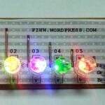
Dr Simon Monk (who has written a book on the Pi and Python – check it out on Amazon) has come up with a really useful idea: a bit of paper you can install over the GPIO pins of your prototyping Pi (and leave there) to remind you which pin is which.

The simplest ideas are the best, aren’t they? Visit Simon’s site to download and print your own version for free.


69 comments
NickMon68
LOL thats so simple it’s brillant.
ColinD
Yes it is *lol*. Almost as good as the tension sheet…
stephen
lol, but then i tried to simple, and found post-its are a bit bog for all 20 pins in a small space
canibalimao
What a basic and excellent idea! But there is a problem: the link is offline :(
liz
Oh dear – the Pi effect strikes again. Happens sometimes when we blog or tweet something; his servers will have been overwhelmed. Wait a while and try again – and sorry, Simon!
Fritz Katze
One might ask:
Rev.1 and Rev.2 versions needed?
What version was used?
Vincent Willcox
I too would like to know this!
Can somebody let me know? Mine is a REV1 board and I want to make sure it is correct.
Thanks.
Andrew Scheller
Well that’s confusing! Checking his image against http://elinux.org/RPi_Low-level_peripherals shows that he’s used the GPIO numbers for the Revision 1 board. And yet looking at his photos, his Pi has mounting holes, which indicates he actually has a Revision 2 board.
:-/
psergiu
Even on the Rev.1 boards, some of those pins marked as N/C are actually +5V or GND.
Brilliant idea, waiting for an updated image.
killor
The legends of the template are the REV 1.
See source link. http://elinux.org/RPi_Low-level_peripherals
RaTTuS
http://webcache.googleusercontent.com/search?q=cache:http://www.doctormonk.com/2013/02/raspberry-pi-and-breadboard-raspberry.html <- cached version
liz
Thanks Rattus!
KentGeek
This is absolutely genius. Just printed one off and put it on my old style model B. Looking forward to not having to count tiny pins down with my silly long-sighted eyes any more!
Tom
great idea!
Looks like you slashdotted his website, though. Or Rasperry Pi’ed in this case :)
Jim Manley
I like this so much that I’ve made similar tags for the HDMI, USB, Ethernet, power, audio and SD card interfaces … not for the pinouts, just the ports so I know which cable to connect to what. Old age is such a pain … what did I come in here for, anyway? :D
Patrick
Great idea, but it won’t fit inside a case.
Rich Kavanagh
What a brilliantly simple idea!
Don Isenstadt
Fantastic idea.. What % do you print it at to get the right size?
Maarten Cammaert
Great idea!
… and I ordered my Pi cobbler kit a week ago :D
Davisnz
Nice idea! Maybe someday I will try it, Original! Thanks.
JBeale
Note that there are no GPIO pins which are genuinely “N/C” (no connection or No Connect) on any version of the Pi. The Rev.1 documentation originally had several marked that to allow for possible future pinout changes, but on the PCB itself they were always Ground or +3.3 or +5V, and are now officially labelled as such. For more detail see http://elinux.org/RPi_Low-level_peripherals
omenie
Some of us have 2 iPads on the desk, open at all times, one with the Pi pinout on screen, the other with the pinout of the 16F688! The PIC for the discerning Pi interfacer!
Or possibly the only PIC I have in the house in large numbers …
CleverEngineer
That is SO smart. Very very clever Dr Simon Monk!
Homer hazel
I think I will try to print this on photo paper to make it a little more durable.
Luke McCarthy
The site is still down but Google has a cached version
http://webcache.googleusercontent.com/search?q=cache:http://www.doctormonk.com/2013/02/raspberry-pi-and-breadboard-raspberry.html
winkleink
I’ve made up a UK A4 page of these after scaling in Inkscape.
With all the extra space I placed 8 each of the Rev1 and Rev2 pinouts on the page.
So, fit to page A4 should work.
Link to the Google+Entry where you can download the file.
https://plus.google.com/u/0/107414156853105102585/posts/BGKhCHzMiHg
Diomedes
Thanks – makes good sense as I have several Rev 1 & Rev 2 boards.
Manxam
Thanks for this update but isn’t GPIO 21 now GPIO 27 on the rev2 boards or am I mistaken?
Andrew Scheller
Yeah, and the GPIO numbers for the I2C pins are different on Rev2 as well… check the wiki link I posted earlier.
M5
So simple and yet so smart. Well done brilliant!
But are the pin outs rev1 or rev2
Mark Symons
Great idea, but Is the REV2 image showing port 27 as 21?
Carson EVans
Paper? near my electronics? I like the idea… but not with paper.
Colin Cameron
What’s wrong with paper+electronics? You never had one of those annoying talking birthday cards?
Benoit Lachance
I might be wrong,
but I believe that
ON REV2 Pin 21 is now pin27…
So the REV2 sticker need to be corrected..
See page 10 of:
http://www.element14.com/community/docs/DOC-51727/l/assembled-gertboard-user-manual
Simon D
I am working on an improved version of this template. However it a) fits the pins, b) it includes rev2 boards.
It is written in LaTeX and results in a PDF. The LaTeX sources aren’t needed unless you want to modify the template. Otherwise just print the PDF, cutout et voila.
winkleink
Thank you Simon for a great idea. With a bit of free time last night I did an updated version with 10 of each type on a single A4 as my expectation is that these things will get mangled when in amongst all the wires so replacements will be need.
Each one is identified as rev 1 or rev 2 and uses the pinout details from http://elinux.org/RPi_Low-level_peripherals
This version also includes pin numbers as sometimes instruction say attach to pin 11 rather than GPIO 17.
Available to download from Picasa
https://picasaweb.google.com/lh/photo/CXpHArbdlZpk5F6l_2jlH9T5abReFwIL0MDnXkIiG4E?feat=directlink
If you print and there is a problem let me know and I can modify.
I love the power of Inkscape
Andrew Scheller
Great work winkleink, you just need to fix the typo on pin 21 – you’ve labelled it as “10 MISO” when it should be “9 MISO” and pin 23 should be “11 SCLK” (on both revisions).
And while you’re at it, if you wouldn’t mind adding CE0 and CE1 labels to pins 24 and 26… ;-)
winkleink
Thanks Andrew.
It’s amazing how you read what you expect to see and sometimes not always what’s there.
Fixed Pin 21 and Pin 23 and added CE0 and CE1 to pins 24 and 26
New Page:
https://picasaweb.google.com/lh/photo/k3vN3HsxB-XmIiVFzzn8jdT5abReFwIL0MDnXkIiG4E?feat=directlink
NOTE: I delete the previous version from Picasa as it is wrong so it will give an error.
Andrew Scheller
Almost perfect now… ;-)
You just need to fix pin 21 on the rev.2 pinouts, and for the sake of consistency I think you ought to change the CE0 and CE1 so that you list the GPIO number before the label.
And if you could get rid of the odd grey circles (make them black) and make the 3.3V labels be orange…
Oh, and a couple of the GNDs on rev.1 aren’t shown in blue.
winkleink
Andrew – thank you so much for looking at this and making sure it’s OK.
As you say almost there, more coffee before starting this type of thing in future…
Again – I have deleted the old link (as it is wrong)
Here is an update version:
https://picasaweb.google.com/lh/photo/YrSLigWPI5ErUpiUrptZ4tT5abReFwIL0MDnXkIiG4E?feat=directlink
rev 2 Pin 21 sorted. and changed order of labelling for CEO 0 and CE 1 to keep it consistent. Also you’re comment below about the transparent background. Now on a White background.
Andrew Scheller
And it looks like you might have exported the PDF with a transparent background, instead of a white background? Not a problem if you’re printing onto white paper, but when I click on the Zoom button on your Picasa page, it all goes black?!?
Andrew Scheller
That was meant to be a reply to my earlier comment to winkleink, and of course when I said “PDF” I actually meant “PNG”, doh!
Andrew Scheller
Thanks for your updates winkleink. You just need to make sure all the rev.1 GNDs are coloured blue ;-)
winkleink
Pooooooooooooooooooo………!!!!!!!!! Thanks again.
Previous one again deleted.
Fingers crossed all sorted this time…
PDF:
https://docs.google.com/file/d/0B23BvTk93HRYOXVwbjVrWHRjbDg/edit?usp=sharing
PNG:
https://docs.google.com/file/d/0B23BvTk93HRYMW9DVnZZNEJ2QkU/edit?usp=sharing
Original SVG (Inkscape):
https://docs.google.com/file/d/0B23BvTk93HRYMHFIY0tMN1ZnclE/edit?usp=sharing
Andrew Scheller
Yup, looks spot on now! Just printed it out :-)
Simon D
Now got a test version of the card for revs 1 & 2.
The issue is that I am working from the wiki which contains some ambiguous stuff; hopefully I have interpretted correctly.
http://www.getthingsfixed.co.uk/raspberrypi
stubright
Hi Simon,
I’ve done a similar one, inspired by your work, in an Open Office spread sheet.
Here’s an enlarged preview, not for printing.
and here’s the ods file
You can edit the pin colours and labels easily without messing up the layout, Since it’s Open Office you can print a PDF directly from it.
Feel free to use it, if you want to.
Stu
stubright
That messed up a bit, the links are there. Just not where I thought.
Preview
https://docs.google.com/file/d/0B5XNQrR9yh_4cXRjUEQ3MmwtZ1k/edit?usp=sharing
ODS File
https://docs.google.com/file/d/0B5XNQrR9yh_4MndNNktuMzN5aVE/edit?usp=sharing
Stu
Mark Symons
Hi Simon, looking at the P5 header in your PDF, the 3v3 and 5v pins appear tranposed. Should p1 be 5v and pin2 3v3?
Simon D
According to the wiki P5 is on the bottom of the board (if you bother to solder it on), so I assumed that the pins would appear reversed.
Simon D
I checked the photos of a rev2 board: and yes the pins are mirror image, cos you are looking from the bottom of the board.
Pin1 is identified by having a square surround hole. See the P1-01. So too is P5-01. However you are looking from the underside so it is reversed.
Andrew Scheller
You’ve got GPIO30 twice on the P5 header?!
Simon D
Oh, yes. Will correct in tomorrow’s version.
One thing that possibly needs correcting is the colour on P1-07. I connects to GPIO 4 and to “CLK0”. The wiki says “GPCLK0” which I read as GPIO, and so should be GPIO colour. So that would make the Rev2 colour for that pin wrong.
In the final version I can lay out a page of multiple Rev1 and another of Rev2s. Depends on what people want.
Any other corrections?
Mark Symons
Hi Simon, I see what it is now. in the PDF the P1 tag is on the left, should be on right with pin 1? It seems it is pins 3 & 4 are transposed.
* Pin 3 – should be GPIO28
* Pin 4 – should be GPIO29
Cheers!
MS
Andrew Scheller
…or maybe the “P1” shown on the P5 pinout should actually be “P5” ?
And it looks like most of the P5 labels are in the wrong places.
Regarding GPCLK0 – the BCM2835 datasheet linked to from http://elinux.org/RPi_Hardware#Components just says “General purpose Clock 0” with no indication of how to use it, so maybe it shouldn’t even be included on your PDF?
And I wonder if the (tiny) pin-numbers are too close to the crosses so that they’d become unreadable when the pins are poked through?
What’s the P.D(IN) about?
Andrew Scheller
Note that I’ve just made some corrections and additions to http://elinux.org/RPi_Low-level_peripherals
Simon D
I think I have read the new wiki correctly, so here’s the new version:
http://www.getthingsfixed.co.uk/raspberrypi
So far as P5 is concerned: I will get a new guide dog, and not mirror things when not necessary.
The P1 or P5 text is now placed roughly where you would find it on the board relative to the card.
The tiny pin numbers are for initial reference to help you get the card the right way round. Once it is in place then it should be “obvious”.
Otherwise do we think we’ve got it now?
Andrew Scheller
Looks good, except you’ve unfortunately got 5V and 3.3V the wrong way around on P5.
And IMHO you should either remove P.Dout from the P1 labels (AIUI it can’t be used by itself), or add P.Clk, P.FS, P.Din & P.Dout to the P5 labels.
I’m liking the positioning and orientation of the P1 and P5 markers :)
I reckon it would be more paper-efficient to have a mix of P1(rev1), P1(rev2) and P5 templates all on the one page, rather than separate pages for each.
Mark Symons
Hi Simon, output values of pins 1 & 2 in latest ‘rpi_gpio.pdf’ are transposed. pin 1 (square pad) should be 5V and pin 2 should be 3v3. I’ve confirmed this with meter. 4.88v at pin1 and 3.29 at pin 2.
All brilliant otherwise as far as I can see.
MS
Simon D
Err, I think I have got the layout right now (see gpio*20130222b.tar.gz).
Also
* tidied up the color boxes so they all line up nicely.
* pages of each version in color and mono versions so covers most bases
Err that’s it?
Andrew Scheller
“Err that’s it?”
I think so :-) Nice work with getting the colour boxes lined up – I didn’t ask about it because I didn’t know how difficult it would be.
If I was being super-nitpicky, I’d point out that the GND boxes get overlapped by the green boxes of 17, 23, & 25. But it’s only noticeable when you zoom in, so I’m not gonna be that picky! ;-)
… actually ignore that – if I zoom in further it looks like it’s merely a PDF rendering issue at certain sizes.
And IMHO a direct web link to a PDF (which you can then open in-browser) is much easier to use than a PDF buried inside a .tar.gz (especially for Windows users!)
Andrew “eye for detail” Scheller ;-)
Simon D
Now done.
Little bits of overlap at high magnification are common-ish. But here doesn’t matter cos at the desired res (100%) and printed on an inkjet you won’t see it. So you get the nerdy highscore today
Also now got the naked PDF for guys that can’t handle tarballs.
Global changes are quite easy with LaTeX cos the document is a program.
OT: LaTeX works as a compiler: feed it a file of text and macros, it whirs and spits out a PDF. The new version includes a lua interpreter so you can do some pretty cool stuff: you get a “proper” language and access to C/C++. For example make a document that does your daily reports: it reads from an SQL database or other log, creates some typesetting codes and outputs a pretty PDF.
LaTeX available for RPi. If you get the texlive DVD you can update it independent of the .deb mechanism of the rest of your distro.
Simon D
Now done.
Little bits of overlap at high magnification are common-ish. But here doesn’t matter cos at the desired res (100%) and printed on an inkjet you won’t see it. So you get the nerdy highscore today :-).
Also now got the naked PDF for guys that can’t handle tarballs.
Global changes are quite easy with LaTeX cos the document is a program.
OT: LaTeX works as a compiler: feed it a file of text and macros, it whirs and spits out a PDF. The new version includes a lua interpreter so you can do some pretty cool stuff: you get a “proper” language and access to C/C++.
For example make a document that does your daily reports: it reads from an SQL database or other log, creates some typesetting codes and outputs a pretty PDF.
Or more conventionally you write a big document with references. It will automatically goto online databases, recover the references and tuck them in the document.
LaTeX available for RPi. If you get the texlive DVD you can update it independent of the .deb mechanism of the rest of your distro.
Andrew Scheller
Here’s the direct link to Simon D.‘s PDF, for people new to this thread:
http://www.getthingsfixed.co.uk/raspberrypi/gpio_template__20130222c.pdf
OT reply: I’ve never delved into LaTeX, but I have used python, LibreOffice and Uno to automatically generate PDFs (in this case business invoices).
Haven’t thought to try getting it working on the Raspi, but as it’s the weekend soon… ;-)
Simon D
Here’s the direct link to the current PDF, for people new to this thread:
http://www.getthingsfixed.co.uk/raspberrypi/gpio_template.pdf
Andrew Scheller
For people new to this thread, also note that “Simon D.” and “Dr Simon Monk” mentioned in the original article are actually different people! ;-)
Simon D.‘s Raspberry Leaf PDF looks slightly different to the one shown in the main article, but works just as well.
Idleman
Great idea !!
I have made similar leaf wich integrate wiring pin port + mini doc on my blog :
http://blog.idleman.fr/?p=2218
It’s in french but the PSD file is online too for modifications
Philip Ashmore
I created a project in SourceForge () to store files and track changes.
The “payload” is an Asymptote file you can use to generate a PDF document, the idea being to print a v1 pinout on the front and a v2 pinout on the back, so you save on paper.
I got as far as the actual leaf, but laying them out is, apparently, beyond my pay grade.
Anyone who can spot the problem can join the project!
Once that’s solved the only remaining issue is if a Rev 3 ‘PI comes out, ’cause then I’ll need three sided paper.
Philip Ashmore
That’s the last time I’m posting with Firefox – I’m using Google Chrome for this post.
The project is .
Comments are closed