Raspberry Pi Pico-powered fibre optic display
This unique Raspberry Pi Pico-powered display produces some amazing arty effects. Phil King shared this mesmerising project in the latest issue of The MagPi.
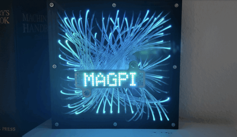
We’ve seen a wide variety of displays used in projects, but none quite like this. With a standard 16×16 NeoPixel LED matrix board connected by optic fibres to a grid of tiny holes in a smaller 35×7 front plate, it results in some cool colour effects from the light leaking from the sides of the fibres. To get the full impact, check out the video on ElliotMade’s YouTube channel.
Elliot tells us the concept is a natural extension of the word clocks he’s made previously. Having been introduced to Raspberry Pi Pico on a course at teachmepcb.com, he opted to use it for this project: “It fit the requirements for this display, plus all of the other good reasons: it’s cheap, easy to get, runs CircuitPython, really easy to use, and has pretty great coverage in the community online.”
After spending a year or two thinking about the idea – in which time he learned to use the SolidWorks CAD software, which came in useful – Elliot set about building the innovative display. “I spent a week of evenings and one weekend to knock out the mechanical construction and to get some basic code running.”
Sandwiched plates
The build comprises a number of plates, designed in SolidWorks, sandwiched together. At the very front, held by two metal rods, the main display grid has 35×7 tiny holes connected with optic fibres via a front plate to the LED matrix board behind, whose rear is supported by a middle plate. An optional back plate is used to mount the electronics, including Pico.

One of the main challenges was plugging all of the optic fibres in place: “They were not completely uniform in thickness,” says Elliot, “so some fit easily, some were loose, and some didn’t fit at all – by the end of it, my fingertips were pretty sore from threading them all in.”
Always up for a fun challenge, he opted to make the plates on a CNC machine, milling their shape and drilling every small hole, which wasn’t without its difficulties. “I used the same kind of solid carbide drill bit that is used in PCB manufacturing, which in hindsight was probably not a great choice for aluminium – they are very easy to break, particularly if the flutes fill up with chips in a hole. My CNC mill tops out at 3800 rpm as well, which isn’t the best for small-diameter tools like this.”

However, he says that anyone wanting to replicate the project could 3D-print the plates instead. “In fact, another user on Instructables took my files and printed his own version and it looks like it turned out great! This design is also quite easy to make with a laser cutter.”
Coding the matrix
With the hardware assembled, Elliot set about creating the Pico firmware to run it in CircuitPython, which he found challenging. “I code at a hobbyist level, so it takes a lot of effort to get what I want to actually happen. CircuitPython was a big help: it makes it super-fast to test changes by simply saving a file on the device and letting it reboot.”

An array in the code is used to map 245 of the LEDs on the matrix to the corresponding positions in the 35×7 front display panel, as connected by the optic fibres. This makes it easy to adapt to show any text or pattern. So far, Elliot has used the display as a digital clock (with an RTC) and for scrolling text/graphics and animated effects, but “it can do just about anything you want, only limited by your imagination.”
Get The MagPi #118 NOW!
You can grab the brand-new issue right now from Tesco, Sainsbury’s, Asda, WHSmith, and other newsagents, including the Raspberry Pi Store in Cambridge. You can also get it via our app on Android or iOS. And there’s a free PDF you can download too.

You can also subscribe to the print version of The MagPi. Not only do we deliver it globally, but people who sign up to the twelve-month print subscription get a FREE Raspberry Pi Zero 2 W!


No comments
Comments are closed