Creating the camera board
Liz: We’re very close to being able to release the $25 add-on camera board for the Raspberry Pi now. David Plowman has been doing a lot of the work on imaging and tuning. He’s very kindly agreed to write a couple of guest posts for us explaining some more for the uninitiated about the process of engineering the camera module. Here’s the first – I hope you’ll find it as fascinating as I did. Thanks David!
Lights! Camera! … Action?
So you’ve probably all been wondering how it can take quite so long to get a little camera board working with the Raspberry Pi. Shouldn’t it be like plugging in a USB webcam, all plug’n’play? Alas, it’s not as straightforward as you might think. Bear with me for this – and a subsequent – blog posting and I’ll try and explain all.
The Nature of the Beast
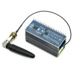
The camera we’re attaching to the Raspberry Pi is a 5MP (2592×1944 pixels) Omnivision 5647 sensor in a fixed focus module. This is very typical of the kinds of units you’d see in some mid-range camera phones (you might argue the lack of autofocus is a touch low-end, but it does mean less work for us and you get your camera boards sooner!). Besides power, clock signals and so forth, we have two principal connections (or data buses in electronics parlance) between our processor (the BCM2835 on the Pi) and the camera.
The first is the I2C (“eye-squared-cee”) bus which is a relatively low bandwidth link that carries commands and configuration information from the processor to the image sensor. This is used to do things like start and stop the sensor, change the resolution it will output, and, crucially, to adjust the exposure time and gain applied to the image that the sensor is producing.
The second connection is the CSI bus, a much higher bandwidth link which carries pixel data from the camera back to the processor. Both of these buses travel along the ribbon cable that attaches the camera board to your Pi. The astute amongst you will notice that there aren’t all that many lines in the ribbon cable – and indeed both I2C and CSI are serial protocols for just this reason.
The pixels produced are 10 bits wide rather than the 8 bits you’re more used to seeing in your JPEGs. That’s because we’re ultimately going to adjust some parts of the dynamic range and we don’t want “gaps” (which would become visible as “banding”) to open up where the pixel values are stretched out. At 15fps (frames per second) that’s a maximum of 2592x1944x10x15 bits per second (approximately 750Mbps). Actually many higher-end cameras will give you frames larger than this at up to 30fps, but still, this is no slouch!
Show me some pictures!
So, armed with our camera modules and adapter board, the next job we have is to write a device driver to translate our camera stack’s view of the camera (“use this resolution”, “start the camera” and so forth) into I2C commands that are meaningful to the image sensor itself. The driver has to play nicely with the camera stack’s AEC/AGC (auto-exposure/auto-gain) algorithm whose job it is to drive the exposure of the image to the “Goldilocks” level – not too dark, not too bright. Perhaps some of you remember seeing one of Dom’s early camera videos where there were clear “winks” and “wobbles” in brightness. These were caused by the driver not synchronising the requested exposure changes correctly with the firmware algorithms… you’ll be glad to hear this is pretty much the first thing we fixed!
With a working driver, we can now capture pixels from the camera. These pixels, however, do not constitute a beautiful picture postcard image. We get a raw pixel stream, even more raw, in fact, than in a DSLR’s so-called raw image where certain processing has often already been applied. Here’s a tiny crop from a raw image, greatly magnified to show the individual pixels.
 Surprised? To make sense of this vast amount of strange pixel data the Broadcom GPU contains a special purpose Image Signal Processor (ISP), a very deep hardware pipeline tasked with the job of turning these raw numbers into something that actually looks nice. To accomplish this, the ISP will crunch tens of billions of calculations every second.
What do you mean, two-thirds of my pixels are made up?
Yes, it is imaging’s inconvenient truth that fully two-thirds of the colour values in an RGB image have been, well, we engineers prefer to use the word interpolated. An image sensor is a two dimensional array of photosites, and each photosite can sample only one number – either a red, a green or a blue value, but not all three. It was the idea of Bryce Bayer, working for Kodak back in 1976, to add an array of microlenses over the top so that each photosite can measure a different colour channel. The arrangement of reds, greens and blues that you see in the crop above is now referred to as a “Bayer pattern” and a special algorithm, often called a “demosaic algorithm”, is used to create the fully-sampled RGB image. Notice how there are twice as many greens as reds or blues, because our eyes are far more sensitive to green light than to red or blue.
The Bayer pattern is not without its problems, of course. Most obviously a large part of the incoming light is simply filtered out meaning they perform poorly in dark conditions. Mathematicians may also mutter darkly about “aliasing” which makes a faithful reconstruction of the original colours very difficult when there is high detail, but nonetheless the absolutely overwhelming majority of sensors in use today are of the Bayer variety.
Now finally for today’s posting, here’s what the whole image looks like once it has been “demosaicked”.

My eyes! They burn with the ugly!
It’s recognisable, that’s about the kindest thing you can say, but hardly lovely – we would still seem to have some way to go. In my next posting, then, I’ll initiate you into the arcane world of camera tuning…


132 comments
Texy
First!
Can’t wait ;-D
Texy
Rune
It is the last day of April.
Where can I get one?
Erik Teichmann
Will this be released within six months or so? I have a project that I need to complete before next year and am wondering if this would be a good option, or if I should go with a USB webcam…
liz
We’re planning on an April release.
Erik Teichmann
Great! Will look forward to ordering my Pi with the camera!
Sancho
Be aware, that the USB webcams do not like Pi a lot – most of them do not work correctly, or at least do not work at higher resolutions/framerates.
wei wang
Great~! How can I get the source code? Because I’d like to add a lot kind of camera based on Raspberry Pi platform.
Thanks~!
sunil
Hi Wang,
Do you have access to ISP source code. We in one of our project are also planning to use a Sony Imager , but due to lack of documentation not able to move ahead.
Will appreciate your help.
Thanks
James Hughes
No-one outside Brcm or the Foundation has access to the source code, the ISP documentation, the compilers/assemblers (The GPU has a custom scaler/vector core) or indeed the knowledge base required to do camera work.
Andrew Scheller
Cool article! I read the “At 15fps (frames per second) that’s a maximum of 2592x1944x10x15 bits per second (approximately 750Mbps)” and thought “hang on a minute, hasn’t he forgotten to include all 3 colour channels”, but then reading on I found this was explained by the Bayer pattern.
The Raspberry Pi is continuing to be surprisingly educational, please keep it up! :-)
Will the camera software be able to provide a monochrome version of the raw Bayer pattern? (if I’m understanding this right, a monochrome version would still be “correct” and would avoid the demosaicking and aliasing steps?)
bernd71
You have to create a monochrome version out of the color image. Because of the (Bayer) color filter on top of the sensor you can’t get a valid monochrome image.
bernd71
But if I remember right it should be possible to get the raw image without debayering. But this is not a monochrome version af the captured image, it is color filtered.
Andrew Scheller
Yeah, I think you’re right. A monochrome version of the Bayer pattern would only be correct if everything the camera was looking at was itself monochrome (i.e. equally ‘bright’ in all 3 colour channels), which is obviously extremely unlikely!
Here’s what the above raw image looks like when converted to monochrome http://www.andrewscheller.co.uk/raw_mono.png
Andrew Scheller
I’ve just managed to work out that the raw.png image actually corresponds to the lower-left corner of the white square on the colour testcard in the demosaiked.png image :)
JamesH
I’ve put an option in the provided apps to store the raw bayer data in the jpeg metadata, you can play with that as much as you like. What I don’t have is an app to extract it though…that will need to come from the community I think.
Andrew Scheller
There’s lots of info on Wikipedia…
https://en.wikipedia.org/wiki/Bayer_filter
https://en.wikipedia.org/wiki/Demosaicing
Having had a look at some of the “External links” it turns out there’s a lot more to demosaicing than I realised!
David Plowman
I think you’d need to “demosaic” (or “debayer”) and then turn to greyscale. If you really want highest quality greyscale images you’d want a sensor without the colour filter array (the microlenses) at all. I know Raspberry Pi is all about having a go for yourself, but removing the CFA with a scalpel and tweezers might be a step too far!! :-)
aaron
removing the CFA basically can’t be done (though i regularly remove focusing optics and cover plate with hot plates and a razor blade), but there are some pretty accurate equations to turn bayer patterns into greyscale images (dont have the reference at home, but could provide it if necessary, the opencv routine is pretty robust so you could start there). I’ve done some work with converting monochromatically illuminated usbcam bayer images to monochrome with opencv and uvc (with other similar ov sensors so likely the same filters), and as long as you dont push the red edge of the detectors too much (greater than ~900-950 nm) it performs pretty well (nearly linear with exposure). it’s really the only way to get a cost effective greyscale image for processing.
George Hampton
Great explanation about the complexity of getting this finished. I’d add a box of crayons spread out in your images. They’re a lot more fun than the standard color test cards.
Cloom
Can’t wait for this camera but I am afraid there will be zillions of orders and thus it will take ages to get it :(
Too bad I already have several ideas for this little monster :) I will have to wait a bit!
fsphil
Is there a V4L2 driver being released for the camera or might that come later?
JamesH
Later, we’ve not had time to do anything but some command line applications.
Gordon
There is a couple of people thinking of writing one, but it’s hard work and takes a long time / money!
Are you offering?
fsphil
I’d love to, although I don’t know how much help I could be. I’m normally on the userland side of things, except for the occasional bug hunt.
Mike Kopack
Looking forward to this, and hoping there will be ways to use the GPU to do image processing for things like computer vision type tasks (edge detection, blob detection, etc.) without having to rely upon the CPU…
JamesH
Actually, you may as well do them on the Arm. That’s running up to 1Ghz, whereas the GPU CPU runs at 250Mhz. If you did have access (you don’t) then you could write vector code to take advantage of the 16way SIMD, but that’s pretty difficult stuff.
Gordon
Actually James, they do…
Herman Hermitage has reverse engineered the VPU vector code from the various bits of information available on the web and in the patents and written a compiler and there is a way of getting the videocore engine to execute those blobs…
So in that case you can execute 16 parallel instructions on 2D data at 250MHz! that’s a lot faster than the ARM!
Gordon
ridgelift
“The Pixel Processing Units ( PPUs ) execute the same operation in parallel ( SIMD ) on the 16 element pairs. D[i] = A[i] op B[i] for i=0…15. Despite the name they may be used for a variety of purposes in addition to graphics.”
https://github.com/hermanhermitage/videocoreiv/wiki/VideoCore-IV-Programmers-Manual
That concept will take a few days to sink in.
Definitely the deep end of the computer science swimming pool.
ridgelift
After a bit more reading on accessing the videocore, I am going to have to agree with JamesH.
You don’t have access.
Unless Broadcom goes all open source on the Pi community, the current state of videocore access is akin to grappling hooks thrown over the parapet wall for a peek into the courtyard.
Gordon
Well it is available and does work…
I can’t help the fact that its difficult to understand, unfortunately that’s the order of the day for vector processing, its just complicated by the 2 dimensional register file.
Gordon
JamesH
Hadn’t realised he had got so far with the reverse engineering….I wonder who Herman is…..
That should get people’s dander up!
ridgelift
As always, cheers to the Raspberry Pi for providing a wonderful teaching tool and springboard for the study of various areas of the computing world!
coppermine
Nice post! Explains more internal workings of a camera! Looking forward to see similar style explanations for further stages and up to V4L2 driver layer if I may :)
kolloth
Can you ask the software guys if they can expose an API for the CSI port so it can be used as an external completely self contained bus?
Essentially what i want to do is hook the CSI port (including the I2C bus) up to an FPGA and use it to input data into the rasppi.
All low level stuff, no need for any processing of the data in the pi, just get the data in from the CSI.
Andrew Scheller
Is SPI not fast enough for what you want to do then?
AIUI only the “GPU-side” is fast enough to handle the data-rates from the CSI port (the ARM may not be able to keep up?), and obviously us mere mortals are unable to write code for the GPU-side.
JamesH
I don’t think that will be possible. The CSI port is on the GPU, there simply isn’t the data rate available to then get that to the Arm.
Gert
Not simply possible I am afraid. The CSI interface requires a special analogue front end which the Xilinx does not support. You need to add a special parallel to CSI converter chip. Those are not cheap neither simple to setup and control.
rickman
What do you mean the CSI requires an analog front end? The CSI interface is purely digital. From the spec I have seen it is also one way with the camera driving both the clock and the data (not counting the I2C control port).
renambot
I see that the chip has support for ‘frame synchronization’. Is it going to be exposed to some API ?
I have a project that needs multiple cams to be sync’ed accurately. Supporting this would be very nice.
Gordon
Its possible, but how are you going to communicate between the Pi’s ? Are you guaranteed a low latency between the different Pi’s? If not the sync signals are not going to be accurate.
If you do have acurate syncs then you can adjust the blanking intervals on each camera to synchronise them (that’s what I did on the 3D camera’s I blogged about recently)
Gordon
renambot
I was wondering if one could wire all the sync signals between the cam modules themselves (indeed without going through the Pi). Otherwise though wired ethernet maybe.
How does one adjust the blanking intervals ? That seems interesting (I had indeed seen it in the previous post, but you were going through a USB communication).
Luc
Andrew Scheller
Would just using regular GPIOs (with interrupts) be fast enough for this? i.e. have the ‘master’ Pi with GPIO as output connected to ‘slave’ Pis with a GPIO as input? If GPIO is fast enough, could you have one GPIO from the master feeding several slaves in parallel, or would each slave need a separate GPIO pin from the master?
Gordon
Yes,
Basically that’s the way it is done… When I was doing it over USB I was using the GPU USB drivers which are far less latency hit! But the latency in linux is a bit random and could mean pretty poor performance…
I’m just not sure if the MMAL api will allow you to adjust the blanking intervals (I did it on the GPU!) Might have to add an interface…
Gordon
Riccardo
The Ribbon cable..will it be detachable on the camera side?
if we would like a longer cable what would we order from RS/Farnell/element14?
How many pins and at what pitch are the pins?
JamesH
15 way, not sure of the pitch – small! But going much longer than 15cm may well not work, as the signal will degrade. 30cm might be possible.
It is detachable at both ends.
Jevan
Will that tiny ribbon cable between the PCB and the camera be detachable? I’m interested in separating the camera from the board and connecting the two with a longer cable.
JamesH
No, that cable is very firmly attached to the camera!
liz
We’ve only tested the length of cable the camera will come with – as James says, you risk signal degradation with a longer one, but you’re very welcome to try!
Jevan
Thanks James, Liz.
I was worried that was going to be the answer :-/ I think I might leave it where it is!
ridgelift
Visual odometry for outdoor ground vehicles.
C’mon on li’l Pi Image Signal Processor! We know you can do it in real time!
Paul
I just did a bit of schoolbook math (1920x1080x10x24/1024/1024) and came out with 474.6Mbps. Can the camera/RPi support HD video recording speeds? Is there a pipeline through the RPi that can say encode the image in the GPU on the fly and be able to write the resultant stream to storage media of some form? Is the USB2 bus fast enough to record at this rate? Could you also encode a compression codec in the GPU at the same time as doing Bayer interpolation and maintain a rate of 24fps? I know that HD cameras are getting cheap but the thought of building one around an RPi just has my mind reeling.
JamesH
Yes, on release you will be able to record up to 1080p30 video to H264 to the SD card at up to about 30Mbits/s data rate.
Paul
Ok, my mind is now blown. I can’t wait to get my hands on this little beastie (me and half a million other people). Thank you so much for your hard work.
Gordon
half a million, I certainly hope not or my release plan is screwed!
Gordon
Jim Manley
Outstanding info – can’t wait for the next episode of “As the Camera Turns”! Now I know what it was like for my parents to wait breathlessly to listen to the next episodes of radio serials in the 1930s …
For the few speed-readers who might make the same mistake, at first I was thinking 30 M_BYTES_/s and how can the SD card interface handle that without the high-speed transfer mode? Then my visual and semantic synapses finally synchronized and I realized that 30 M_BITS_/s only about 3.75 MB/s, well within even most slowpoke SD cards’ transfer speeds. Whew! That made me do the dog-tilts-his-head maneuver for a second! :D
Micha1982
Hi, only want to mention that the Bayer-sensor is not the only way to take photos – there are others like Foveon, too ;)
But great projekt, your cam would be a fine piece to play with :)
Rob V
yeah, +1
i researched this about 10year ago, and each sensor well measured electron count as the temperature of the colour and an overall reading was taken independently for a black-and-white exposure level.
i didnt know about Bayer. there must be a reason why that technique ha s become prevalent. quality? speed? cost? who knows?
David Plowman
I think Bayer wins for the usual reason – cost. Foveon sensors have tended to be restricted to a few high end niches, Sigma perhaps the most obvious example. Foveon certainly has some technical advantages – lack of colour aliasing problems for a start – but the Bayer sensors are generally able to cram way more pixels (in the sense of single-colour-value pixels) on which helps their resolution.
If you search “Foveon versus Bayer” you’ll find some comparison articles, such as this one: http://www.dpreview.com/articles/7262838870/foveon-verses-bayer-sensors
The author seems to like the Foveon sensor, though it seems to me it may be for reasons other than the fundamental sensor type, namely colour reproduction and the general tone of the processing. More on this sort of thing in my second (and final!) blog post on the subject of the Pi camera!
GGraham
“fixed focus module” – I am considering using an RPi with camera for imaging through microscopes and telescopes. Can the lens be removed? Is there an IR filter as well?
liz
No and yes: this is the sort of camera you’d find on a mobile phone.
Tom Reader
I’m hoping to use it for that too – I have an active project ‘on the go’ in astronomy, and had thought about using it for microscopes (focus stacking, for example). It had occurred to me that as a very small (physical size, I mean, not resolution) sensor, it might avoid some of the problems of barrel distortion etc that can happen when trying to use a DSLR for photomicroscopy. But I’m not an expert.
Unfortunately I don’t tend to get any lower-level than OpenCV, so I’ll have to wait until driver support gets up to that level, and I’m not sure I’m going to be able to help much in the process.
David Plowman
Using a sensor as tiny as this for astronomy sounds challening, to say the least, so microscopy is probably a better bet! Another catch is that these sensors can have defect pixels (a bit like flatscreen monitors and tellis can) only in the case of image sensors there can be *thousands* of them (though the ov5647 seems pretty good to me in this respect). In low light the processing chain works pretty hard to spot and remove them… which could have rather damaging effects on astro-pictures! Who stole the Milky Way?
Andy
Hmm. 2952×1944 is well more than 5M – actually 5738688 so I assume we lose some round the edges otherwise they’d call it 5¾M. But what we really get is only half that, depending on how the microlenses are placed over the photosites, and half again for chroma information – only 738 pixels per line, barely more than SD in 4,4,4 (though rather better than you can squeeze out of PAL or NTSC)
We once took a professional (three-tube) SD camera to a disco, with a light show that went red-green-blue-red-green-blue in time to the music. The picture went naff-sharp-naff-naff-sharp-naff in time to the music
Though I bet the lens will be a greater limitation on quality. And my eyesight will remove any last vestiges of focus
JamesH
On the other hand, the pictures look fine at 2592×1944. (which is indeed the native resolution). And although chroma information is indeed half, the actual pixel resolution is as specified.
I sometime feel that if people actually just used this sort of thing rather than analysing it to death, they would be much happier.
David Plowman
Oops, I think that might be a typo. It should be **2592** not 2952. I’ll ask Liz to correct.
Apologies!
liz
Fixed!
Andy
“if people actually just used this sort of thing rather than analysing it to death, they would be much happier” I could argue with that, but I won’t here – it’d go better over a pint.
So are there 2592 green pixels per line and 1296 each of red and blue (5184 total), or only 1296 and 648 respectively?
David Plowman
Every line has 1296 green pixels and *either* 1296 red *or* 1296 blue pixels. They alternate like this:
RGRGRGRGR…
GBGBGBGBG…
etc.
Andy
Thank you.
Particularly for not making me look stupid by saying “look at the picture”
Who said something like “keep quiet and you’ll be thought a fool. Open your mouth and you’ll prove it”
James
Any word on how much power the camera board will require?
JamesH
Never been measured, but I did find that using my 0.85A Kindle charger, when I plugged in the camera I started getting keyboard repeats, whereas I didn’t without. So there is a drain. A 1A charger seems OK.
David Plowman
I’ve run the Pi + Cam (no keyboard or HDMI) quite happily from my laptop USB when out and about taking test shots!
liz
As JamesH says, we’ve not measured it yet – we’ll do that when the release software is finalised, but not before.
James
Thanks. I’m looking to drive the cam and probably a Model A board via solar power, along with a USB Wifi interface, so this is going to be an important question for me.
JamesH
I was using a Model B 256MB, I would think a Model A would be fine with my 0.85 charger.
JamesH
Now have some power figures. Very approximate, but the camera seems to take about 210mA during preview display, whilst the H264 encoder takes about 80-90mA at 5v. Not been able to capture the instantaneous current at stills image captures as its too quick for my equipment,
Darryl
Interesting article. However, as a non-engineer (I’m not even going to pretend to understand fully anti-ailiasing and de-mosaicking and stuff like that) , I’m still not clear on why this new camera takes longer to implement than plug-in USB cameras? (Not that I’m being critical, just inquisitive). Is it because USB camera’s already have the drivers developed, whereas the development of this camera’s drivers is where the effort is?
JamesH
Imagine the development time to be the equivalent of actually designing, building and then writing the software for the USB camera. Not that I know how long it takes to design and develop a USB camera. Which would probably be of a lower quality than this one tbh.
Andrew Scheller
I’m only guessing, but I think in USB webcams all this de-mosaicking etc. is already done in the webcam’s firmware, and the USB interface simply sees the already-processed image data (which means there’s no opportunity for the USB host computer to do anything ‘cleverer’ than what the firmware provides).
As James says, USB webcams are generally low quality (I expect/hope we’ll see more about this quality aspect in the followup ‘camera tuning’ article).
epaperflip
The blog was absolutely fantastic! Lot of great information which can be helpful in some or the other way. Keep updating the blog, looking forward for more contents.
LKO
This is going to be very exciting to work with! I’ve got some robotics/OpenCV, smart dashcam, and other ideas just waiting for me to get my hands on some of these cameras. I’m gonna need some more Pi’s, too…. Gads, all this Raspberry Pi stuff is like tinkerer’s catnip.
Michael
let me know how it goes with OpenCV, I’ve been using it with an ip camera to detect simple features and the Pi is slow as molasses.
Gordon
Yes,
Depends on your definition, is the Pi too slow or the software too inefficient?
You can’t do anything about the first… (except overclock)
Gordon
LKO
I figure the camera module/GPU will take a lot of load off the Pi, since the module will enable the Pi to record 1080px30 easily, and I haven’t heard anyone getting anywhere near that with a USB or IP camera. The dashcam project won’t need as much processing (motion detection) as the robotics (object recognition). If need be, with the robotics stuff I could still use the Pi for the robotics controller, and offload the computer vision processing to another computer, perhaps. If it weren’t challenging it wouldn’t be as much fun to try to do!
In the end, it’s not as much the result but the adventure that counts with me. I’ll have learned something no matter what. If the Pi can’t handle the load, I’ve got plenty other ideas to try out with a Pi. Already pressed my first Pi into service as the web server/data collector for our weather station, and it’s handling that job excellently.
fastmapper
For those of us who are interested in capturing image acquisition timing, will the vertical sync and horizontal reference signals from the camera be made available to the ARM?
IvanRoulson
Looks like a healthy lunch in that demosaic picture… and it’s already better quality than my webcam. But won’t it be harder to tune the image as it slowly goes mouldy? ;-)
Thanks for all of the effort, folks!
Andrew Scheller
Haha, another project for TimeLapse! http://www.raspberrypi.org/archives/3464
Michael
So how do we access the camera? Will it be in the
/dev/video0
list?
Andrew Scheller
Nah, access via /dev/video needs a V4L2 driver that people have been asking about above.
https://en.wikipedia.org/wiki/Video4Linux
Dimitri R.
Is there a mailing list I can get a notice the second it is available for purchase? Really looking forward to get my hands on one.
bluseychris
What about the DSI connector, will we see a screen for that?
JBeale
I have done some tests on other cameras (eg. http://www.bealecorner.org/red/test-080108/index.html ) and I look forward to the release of this one so I can play with it!
Sriram
What is the dimension of the module?
Andrew Scheller
If you click on the “camera board” tag at the top of this page, you’ll find several other relevant blog posts, including this one where the dimensions are mentioned in the comments :)
Devangini
Is it possible to upload the images captured by the camera to some server through a rest service?
Andrew Scheller
Of course it is – just write some code in your favourite programming / scripting language telling the yet-to-be-released command-line-utilities JamesH is working on to take a picture, and then do whatever you want with the captured image (including uploading it to some server through a rest service).
JamesH
Now I’ve got the hand of the camera code by way of the command line apps, I’m probably (if I have time) going to write a C library to provide access to the camera system which should then be wrappable in Python or whatever.
Or if I don’t have time, I have very specifically made the command lines apps as easy to understand as I could, with doxygen comments etc. Running through pccabe (a complexity analyser) shows the code is well within understandable limits. So it sound be a relatively simple job to modify the code to your own purposes.
Gareth Jones
Will the command line apps be similar to gphoto2? That’s pretty much the standard for controlling cameras over usb. Having something that’s syntactically similar would minimise the learning curve to get the attached camera doing similar things to a tethered camera
JamesH
Nope, I wrote them from scratch with no previous knowledge. They are pretty simple to understand though, and I have written some basic documentation.
For example,
RaspiStill -o image.jpg -t 2000
will take a picture calls image.jpg after 2000ms, using a full screen preview. Don’t want a preview?
RaspiStill -o image.jpg -t 2000 -n
Or
RaspiVid -o video.h264 -t 10000 -fps 10
will take a 10s video calls video. h264 at 10 fps using default bitrate.
So all pretty simple. There’s loads more options, if you want more complexity.
Gareth Jones
James, can’t seem to reply to your latest comment – guess I’ll have to wait and see what you’ve written and how we can use it – meanwhile, I’ll stick to my D3!
JamesH
Also, one of the reasons for writing them as they are was to make them as simple as possible so others could take the code and modify it as they wish. Adhering to an existing interface might have made that more difficult.
Art Gibbens
I must confess I did not read all the comments – but if nobody has asked yet, will this camera be tethered or hard mounted? I ask, because if it was tethered/wired and able to be positioned/mounted in a small tiny capsule/bay I have a 3 inch diameter mid-powered rocket that would like to stream live video to a receiving laptop at the launch sight. If it’s hard mounted at a 90 degree angle on a board, then it’s not so ideal. If it is on the end of a cable that could be strapped/mounted at any given angle – it would be a much nicer add-on. Looking forward to what you come up with.
rod holland
Listen…can anyone use this camera product in conjunction with the raspberry pi to help us make a simple colour videophone that will work over a network. We have a market for it. We have ideas for other products as well. We are sales guys not programmers so we need your expertise and we are happy to pay if you product can be figured out.
Andrew Scheller
Once (if?) Video4Linux2 drivers get written for the camera board, you’ll be able to use it with *any* video-phone / video-conferencing / instant-messaging software that runs on Linux. (might be easier/cheaper to wait for a VFL2 driver than to develop some custom protocol/application that works with the current camera driver?)
Don’t forget that you’ll also need to hook up a USB microphone too.
JBeale
The camera board is separate from the R-Pi and quite a bit smaller than it. They are connected via a flex cable. Have a look at the photo: http://www.raspberrypi.org/phpBB3/viewtopic.php?f=43&t=32605#p279863
For a rocket big enough to contain the R-Pi itself, I’d think there would be plenty of room to tilt and swivel the smaller camera board, which appears to be less than 25mm in the long dimension.
Zap Andersson (@MasterZap)
Please please let us get to this sensor as RAW AS POSSIBLE. I work in image processing and would ideally want the sensor data untouched, or if anything, the debayered thing in full bit-depth. PLEASE DO NOT MUCK AROUND WITH EXPOSURE CURVES AND DYNAMIC COMPRESSION IF I DONT WANT THEM!! THIS IS MY JOB!!! Gimme ALL teh bits! :)
/Z
JamesH
Tell you what, you stop shouting, and read some of the comments, and you will be able to find all the answers to your questions…
But because I’m in a good mood, I can tell you now that there is an option in the apps I’ve written to add the very RAW bayer data to the JPEG metadata.
The GPU itself does a very good job at processing the image (that’s its job..), and does it in real time which will not be possible when processing on the ARM, so as long as you don’t mind the slowness, you can process away to your hearts content.
JL
Is there an option to connect 2 of these cameras to one PI? E.g. to process stereo images?
JamesH
No, only one CSI port is exported on the Raspi. (The GPU supports two)
Andrew Scheller
So, now that we’re getting more details about the camera board, could you explain (in context) the reason for the I2C channels being swapped over on the Rev2.0 Pis? http://www.raspberrypi.org/archives/1929
Does this mean some things regarding the camera will “work differently” on Rev1.0 boards?
JamesH
Don’t think so, I’ve been developing the Linux software on board #0000000001 but others have been using the camera on much more recent ones than that!
liz
Not at the moment – there’s only one CSI connecter. You’d need to link two Pis if you wanted to do that.
liz
Snap!
Andrew Scheller
LOL :)
Andrew Scheller
Nope, while the BCM2835 has 2 CSI interfaces, only one of them is exposed on the RaspberryPi board, and the other one is inaccessible.
More in the comments on http://www.raspberrypi.org/archives/3376
Iyanus C. McKanovich
May I ask what stock the various suppliers will have access to?
Having searched for many years for ways to do a sub 500 UKP megapixel camera that doesn’t involve USB horrible-ness and 0.5 FPS, a low cost e.g. 100 UKP 5MP intelligent CCTV camera unit (pi, case, camera, storage) is “quite simply, terribly splendid!”
Hardware motion detection on GPU would be a nice to have, but without that, I still have plans to buy at least 50 cameras for various projects I have (and the resultant Pi sales).
I predict that the likes of Swann / Axis / GeoVison will seriously have to up their game if they are to compete with home / light commercial use case that this combo can so brilliantly address!
If you have over 1 million cameras per stockist, you may even not run out in under a week!
Good Luck (and thanks! – the camera signal de-coding sounds like less fun than angry ferret wrestling!)
-icm
JamesH
Lowest frame rate I have got so far is 2fps encoding direct to H264. I’ll need to modify the camera settings to get lower than that. But you could just take snapshots every couple of seconds to JPEG for a security camera, and splice them together later.
As to quantities, I do know (well, I did hear one figure that may be wrong of course) how many are being manufactured, and it ain’t 1M/stockist, that would require in excess of £10M (estimate – I don’t know the BOM cost) to manufacture up front!
Gordon
Yeah sorry the initial build quantity is as usual a slow build up, we don’t have the capital of Apple / Sony / Microsoft / etc. to create a million cameras…
James, seriously underestimated the costs!!!
But we are intending on building up the supply quickly!
Gordon
Taz
April is nearly over. Can you tell more details about the release in april?
Pranav
Hi,
It will not have manual control for shutter speed & aperture, right?
JamesH
Correct at this stage – it’s fixed aperture btw, so that could not be changed.
Dan Hudgins
If you email me I can correct the color or Bayer data in my free de-Bayer program that works with my freeish DI software that is up for download on my web site. There are two ways to shoot with sensors, having the analog gain equal for R, G1, G2, and B, or using different analog gain values for red and blue and holding the green gain constant to correct the white balance (at high or low K you may need to add green gain it depends on the color of your IR filter). If you enail me I can tell you what to do, I helped with the corrections and LUT for the KineRAW ™ and some other cameras. Dan Hudgins tempnulbox (at) yahoo (dot) com
Dan Hudgins
I can also measure the Bayer data to figure out what red and blue analog gain values are needed from a white subject like the white patch on the color checker. The exposure should put 90% white subject at no more that 45% ADC linear signal. Using 12bit data mode will give fewer histogram gaps at higher ISO. Panavision ™ puts 100% white subject at about 16% ADC signal level in their digital cinema cameras.
Dan Hudgins
My software supports “raw” data in three formats currently, I could add more options, 16 bit data per pixel, 8 bit data per pixel, and 12bits packed data with two pixels packed in three bytes, 12 bits packed is popular for DNG frames used in Digital Cinema Cameras like Acam dII ™ and Black Magic ™ as well as KineRAW ™.
Dan Hudgins
I can help you figure out the DNG header tags, as the XYZ to RGB and some other tags can be confusing. Really you just need a 512 byte array and to store various headers in files to load for the various resolutions, and then just load the right header for each resolution etc. and the rest of the DNG is just the data, 16bit, 12bit packed, or 8 bit etc. Email me and I can talk you through the details.
JamesH
By setting raw mode in raspistill, the JPEG file produced will have the very raw bayer data in its metadata. This is the data directly off the sensor, nothing done to it at all. Bayer order is BGGR, 10 bit.
Dan Hudgins
Someone sent me some sample JPG with raw data. The problem is that there seems to be padding at the end of each scan line so it does not come out even with five bytes per four pixels, on a horizontal resolution of 2592 it seems to use 3264 bytes per line, and that doen not work out even (?) is there a document for the rule used in the raw data for end of line padding? Also is there a document for the bit order and endian in the five byte per four pixel bit backing format used in the camera’s raw data? In addition to that, is there a rule for the placement in the JPG file for the raw data, and is there a simple way to compute the data block size and it offset from the JPG file header? Another issues is that in time lapse mode, the frame set only has raw data in the first frame, so how do you get raw data in all frames?
liz
You’re more likely to get an answer from the developers if you ask your question in the forums; they’re monitoring those more closely than they will be monitoring this post.
Dan Hudgins
Thanks, I see a thread now that has some information, but there are two problems: 1) The image data is always full sensor image area so it cannot shoot windowed in raw mode to get 24fps at any resolution, 2) that only the first JPG in the time lapse sequence seems to have the raw data in it? So whats up with that…
Anmol Mishra
Hi Dan. I am using a USB3 vision camera – Flea3 in color RAW12 packed mode with RGGB Bayer.
Windowed resolution is 3104 x 1744. Frame rate is 25fps but it wont matter for DNG.
The crop is 496 from X and 208 from Y.
496×208
I have wasted a couple of weeks trying to get a DNG header working.
Would you mind generating one so I can pop it in and test ?
Slava
How can I adjust the exposure time and gain applied to the image that the sensor is producing ?
I am using the uv4l, Video4Linux framework and “raspicam” driver and there is not such option like “gain”. However there is something near that: the
--exposure=night and --awb=autooptions, but these doesn’t seem to do the trick and give a better image during night.Scott MacIntosh
I recently purchased the camera and have been trying to access the raw bayer layer data. What is the best way to extract the raw data that has been embedded into the jpeg meta data?
Thanks!
Comments are closed