Raspberry Pi Compute Module 4 on sale now from $25
It’s become a tradition that we follow each Raspberry Pi model with a system-on-module variant based on the same core silicon. Raspberry Pi 1 gave rise to the original Compute Module in 2014; Raspberry Pi 3 and 3+ were followed by Compute Module 3 and 3+ in 2017 and 2019 respectively. Only Raspberry Pi 2, our shortest-lived flagship product at just thirteen months, escaped the Compute Module treatment.
It’s been sixteen months since we unleashed Raspberry Pi 4 on the world, and today we’re announcing the launch of Compute Module 4, starting from $25.
Over half of the seven million Raspberry Pi units we sell each year go into industrial and commercial applications, from digital signage to thin clients to process automation. Many of these applications use the familiar single-board Raspberry Pi, but for users who want a more compact or custom form factor, or on-board eMMC storage, Compute Module products provide a simple way to move from a Raspberry Pi-based prototype to volume production.
A step change in performance
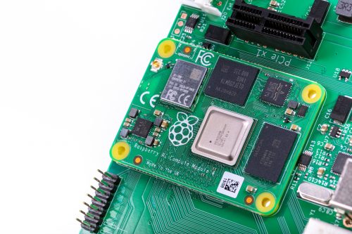
Built on the same 64-bit quad-core BCM2711 application processor as Raspberry Pi 4, our Compute Module 4 delivers a step change in performance over its predecessors: faster CPU cores, better multimedia, more interfacing capabilities, and, for the first time, a choice of RAM densities and a wireless connectivity option.
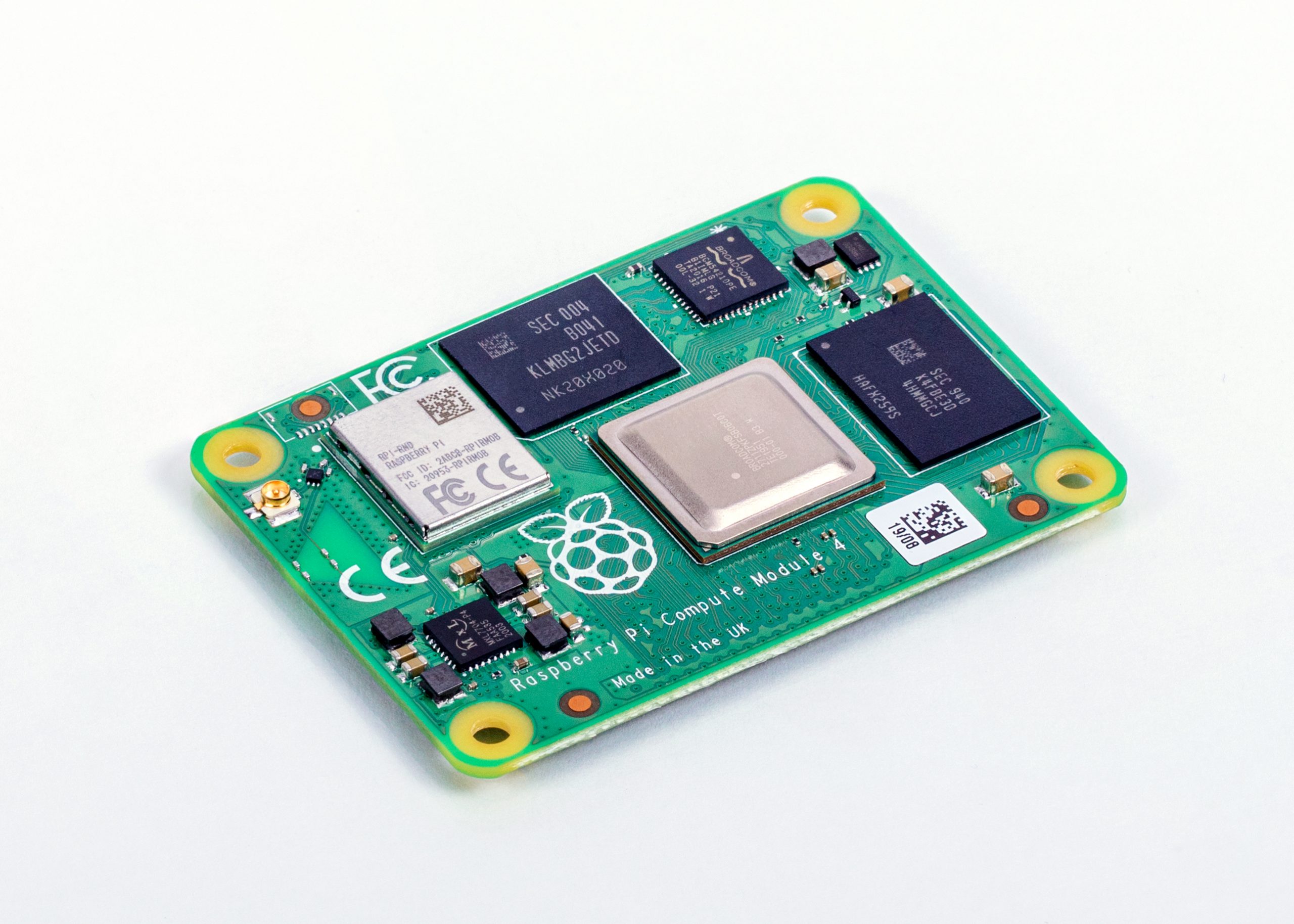
You can find detailed specs here, but let’s run through the highlights:
- 1.5GHz quad-core 64-bit ARM Cortex-A72 CPU
- VideoCore VI graphics, supporting OpenGL ES 3.x
- 4Kp60 hardware decode of H.265 (HEVC) video
- 1080p60 hardware decode, and 1080p30 hardware encode of H.264 (AVC) video
- Dual HDMI interfaces, at resolutions up to 4K
- Single-lane PCI Express 2.0 interface
- Dual MIPI DSI display, and dual MIPI CSI-2 camera interfaces
- 1GB, 2GB, 4GB or 8GB LPDDR4-3200 SDRAM
- Optional 8GB, 16GB or 32GB eMMC Flash storage
- Optional 2.4GHz and 5GHz IEEE 802.11b/g/n/ac wireless LAN and Bluetooth 5.0
- Gigabit Ethernet PHY with IEEE 1588 support
- 28 GPIO pins, with up to 6 × UART, 6 × I2C and 5 × SPI
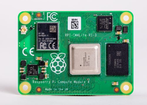
New, more compact form factor
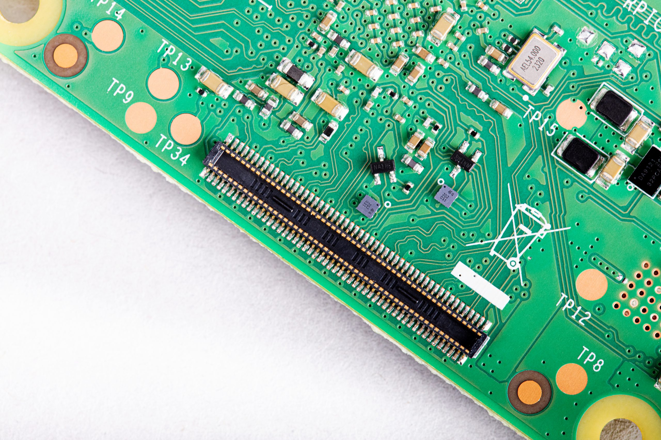
Compute Module 4 introduces a brand new form factor, and a compatibility break with earlier Compute Modules. Where previous modules adopted the JEDEC DDR2 SODIMM mechanical standard, with I/O signals on an edge connector, we now bring I/O signals to two high-density perpendicular connectors (one for power and low-speed interfaces, and one for high-speed interfaces).
This significantly reduces the overall footprint of the module on its carrier board, letting you achieve smaller form factors for your products.
32 variants
With four RAM options, four Flash options, and optional wireless connectivity, we have a total of 32 variants, with prices ranging from $25 (for the 1GB RAM, Lite, no wireless variant) to $90 (for the 8GB RAM, 32GB Flash, wireless variant).
We’re very pleased that the four variants with 1GB RAM and no wireless keep the same price points ($25, $30, $35, and $40) as their Compute Module 3+ equivalents: once again, we’ve managed to pack a lot more performance into the platform without increasing the price.
You can find the full price list in the Compute Module 4 product brief.
Compute Module 4 IO Board
To help you get started with Compute Module 4, we are also launching an updated IO Board. Like the IO boards for earlier Compute Module products, this breaks out all the interfaces from the Compute Module to standard connectors, providing a ready-made development platform and a starting point for your own designs.
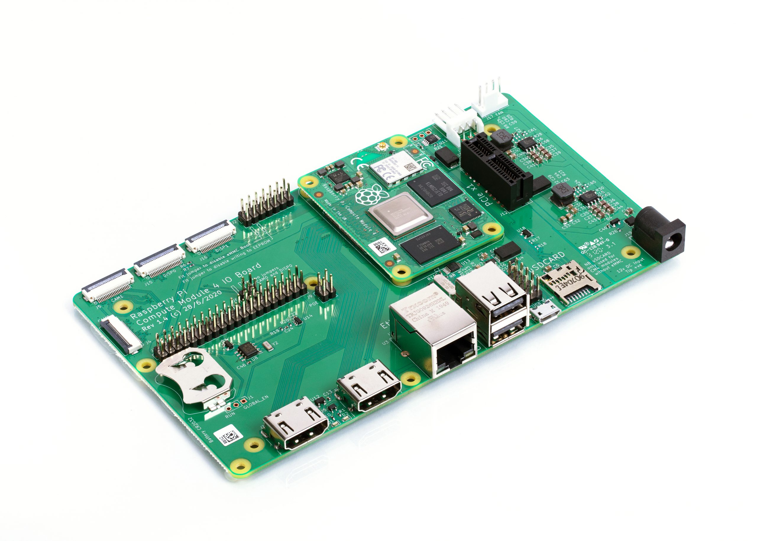
The IO board provides:
- Two full-size HDMI ports
- Gigabit Ethernet jack
- Two USB 2.0 ports
- MicroSD card socket (only for use with Lite, no-eMMC Compute Module 4 variants)
- PCI Express Gen 2 x1 socket
- HAT footprint with 40-pin GPIO connector and PoE header
- 12V input via barrel jack (supports up to 26V if PCIe unused)
- Camera and display FPC connectors
- Real-time clock with battery backup
CAD for the IO board is available in KiCad format. You may recall that a few years ago we made a donation to support improvements to KiCad’s differential pair routing and track length control features; now you can use this feature-rich, open-source PCB layout package to design your own Compute Module carrier board.
In addition to serving as a development platform and reference design, we expect the IO board to be a finished product in its own right: if you require a Raspberry Pi that supports a wider range of input voltages, has all its major connectors in a single plane, or allows you to attach your own PCI Express devices, then Compute Module 4 with the IO Board does what you need.
We’ve set the price of the bare IO board at just $35, so a complete package including a Compute Module starts from $60.
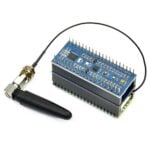
Compute Module 4 Antenna Kit
We expect that most users of wireless Compute Module variants will be happy with the on-board PCB antenna. However, in some circumstances – for example, where the product is in a metal case, or where it is not possible to provide the necessary ground plane cut-out under the module – an external antenna will be required. The Compute Module 4 Antenna Kit comprises a whip antenna, with a bulkhead screw fixture and U.FL connector to attach to the socket on the module.
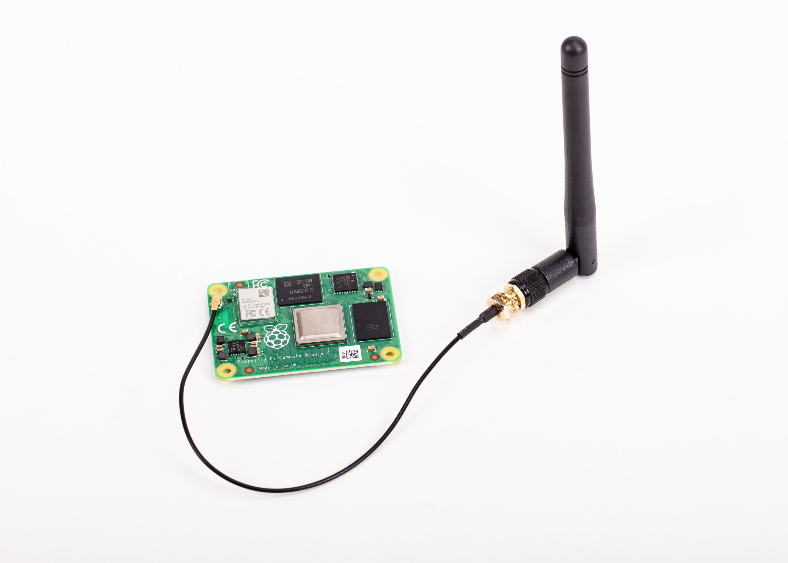
When using ether the Antenna Kit or the on-board antenna, you can take advantage of our modular certification to reduce the conformance testing costs for your finished product. And remember, the Raspberry Pi Integrator Programme is there to help you get your Compute Module-based product to market.
Our most powerful Compute Module
This is our best Compute Module yet. It’s also our first product designed by Dominic Plunkett, who joined us almost exactly a year ago.
I sat down with Dominic last week to discuss Compute Module 4 in greater detail, and you can find the video of our conversation here. Dominic will also be sharing more technical detail in the blog tomorrow.
In the meantime, check out the Compute Module 4 page for the datasheet and other details, and start thinking about what you’ll build with Compute Module 4.


163 comments
Realizator
Wow! Thank you for this great upgrade!!!
Bruce Tulloch
Woo hoo! For deeply embedded designs that need full PCIe with all the bells and whistles of the latest Raspberry Pi, for us it’s the only game in town :)
Looking forward to building with this little beauty.
Jeff Geerling
This is exciting news! With earlier models, there were always some significant limitations when it came to features or performance, but with this model, there’s really no downside besides maybe a little extra power draw (I haven’t tested it yet).
I spent some time playing with a pre-production model and posted about it on my blog, but basically, the Compute Module 4 is _twice_ as fast as the 3+ in CPU testing, and with an NVMe, storage is 6-7x faster than the eMMC (which is also twice as fast as in the 3+ due to its expanded 8-bit bus!).
The Pi Foundation really knocked it out of the park, while keeping the price approachable. I’m excited to see if integrators like Turing Machines can get some new boards out to take advantage of the vastly improved performance and onboard gigabit networking on the CM4.
Alexander
Hey, Jeff.
As an TuringPI user, what are your thoughts on the new layout? Looks like it’s gonna be WAY harder to implement the backplane for multiple CM boards now.
Jeff Geerling
That is true; it’s definitely going to require some creativity. I only know that I asked the same questions and the folks at Turing Machines said they had some ideas, and would still target the Mini ITX form factor for their V2 board!
Keith Lee
If I remember correctly the Turing Pi has a right-angle SODIMM slot for the CM3. You can easily use a Gumstix CM4 Uprev board to replace the CM3 with a CM4 in those slots. Check out https://store.gumstix.com/manufacturer/raspberry-pi/cm4-uprev.html
Julian
NVMe-storage how? There’s no M2-port right. Are you using an adapter in the PCI Express en 2 x1 socket?
Peter Green
Yes he used an adapter in the x1 slot to test the NVMe drive. I’d imagine any production design that wanted NVMe would use a custom baseboard with a M.2 slot instead of the x1 slot.
Keith Lee
Yes, a carrier with M.2 already exists: https://store.gumstix.com/manufacturer/raspberry-pi/cm4-development-board.html
Peter Green
They did, but they priced it at a point where people are going to regard it purely as a dev-kit, not as something they can use as a module in their system.
Nick
Jeff, which PCIE adapter works with this board? We need to build a compatibility list for this new board. :) And does it really support NVMe or it’s actually SATA?
Michael Horne
404 errors from the links to more info about the module by the way
Helen Lynn
We know – fixed now! Something just needed another cup of coffee.
Tobias
Cool… Which WiFi-Chip is used on the compute module.
Raspberry Pi Staff James Adams
Same as Pi4 – BCM43455
CooliPi
Can both antennae work together in MIMO configuration? I mean, use an integrated antenna and an additional one, with different polarization. Could be limited by its IO bandwidth though, but signal quality wise, it would be better than a single antenna.
Petr
How is it connected to the SoC? The datasheet says it can be over PCIe or SDIO, if I read it correctly…
Wouldn’t it be better to use the PCIe for other purposes?
Thanks!
Pallav Aggarwal
This is very exciting news, happy to see an option for eMMC/RAM/Wireless although not a big fan of too many variants to pick from, customer’s find it difficult if too many options are presented moreover I can foresee some variants will become popular and more available and others will die down.
I am not happy with a single USB interface, this creates an issue as in today’s designs we need more than 1 USBs anyway, could have been better to have a USB HUB on the module itself if direct USB connections were not possible.
Do you mean we cannot use SDIO interface if eMMC version is used?
Best Regards, Pallav Aggarwal
Gordon Hollingworth
Not everyone requires more than one USB interface, so the addition of silicon to provide that would be better placed on the host board. The sdhost interface is still available on GPIOs 22-27 so you can add a second SD card or eMMC device to those pins.
Pallav Aggarwal
YEs, got it, but all the projects I have been in discussion with needed more than one USB, always. Anyways there is always be something missing for a particular usecase, thanks for your comment. on SDIO as well.
Mike Edwards
Look closer at the board pic next to the USB ports. There’s a 10 pin header there and a micro usb port, with a silkscreened label which reads ‘USB Slave’. It’s unclear which of those the label refers to, but it seems pretty obvious that there is some form of expandable option for USB on this board.
Mike Edwards
And, further down in the comments, someone linked to an overhead shot of the board on hackaday.
https://hackaday.com/wp-content/uploads/2020/10/DSCF1930_thumbnail.png
It appears the 10 pin header is indeed a separate pair of usb ports, while the micro is the usb slave.
Petr
Hi Gordon!
If using the Lite version, is it possible to use the SD_* interface as GPIO? And are those GPIO34-43 or GPIO48-53+40-43? (I would probably need all of the 6 SPIs and the 6th of them may possibly use the same pins as the SD* interface… Really pitty You didn’t document in the datasheet which signal is which GPIO for all the signals…)
And: is it possible to boot from NVMe without any SD/MMC/eMMC?
Thanks!
bensimmo
I see it that a hub chip takes up a lot of space.
Then you need to decide, do you do the old style B and run of the usb2 connection or 4B style and run of the PCIe connection for USB3 ports.
Either than mean you can’t break that channel out to the pins.
carriers then lack choice, every one get the extra cost and board size increase. If you really need it, then integrate a 4B board…
W. H. Heydt
The SoC only has a single USB port. This is true of *all* SOCs used by Pis to date. In the interest in not putting extraneous items on the CM board that may not be needed by all users, the CM should *not* have an on-board hub. Note that WiFi on the CM4 is optional.
Alex Willmer
There are some unpopulated pads by the FCC logo. What are they for?
Gordon Hollingworth
JTAG debug connector we use to bring up the hardware
AntonPlakhotnyk
Does JTAG connector routed to CPU and allow debug it? Does JTAG conected to GPU WIFI (broadcom IC) or something else then main CPU?
AndrewS
That’s only the JTAG connector for the VPU.
The CPU JTAG connector is available on the standard GPIO pins https://elinux.org/RPi_BCM2711_GPIOs
Anders
Good news, I’m really hopeful now that we’ll see a nicely packaged Raspberry Pi laptop on the market.
Matthew
A laptop with one USB 2 port? No thanks. I’ll wait for the CM5.
mahjongg
The compute modules supports up to 4 USB-2 connections, two through USB-2 connectors, and two though pinheaders
Gray
It’s 2020, so I almost never use the USB ports on my laptop. But, the designer of the laptop could choose to implement a PCIe USB3 bridge if they wanted – though I’d rather see it broken out as an M.2 bay for internal storage, or a TPU, or whatever.
aBUGSworstnightmare
Great news! Like the fact that on-board WIFI is available as an option. Also like the price point of the new CM4IO as it is a must for getting started with the new CM4 lineup.
Maico
Oh man… it’s so exciting. I foresee a lot of interesting stuff based on this module.
Richard Brooksby
Please add current draw and/or wattage to your specs.
Richard Brooksby
w00t, here it is https://datasheets.raspberrypi.org/cm4/cm4-datasheet.pdf#consumption-table
Thanks.
John King
Wondering why this is not available for sale in the UK yet?
Alex Bate
Check out the Farnell website. You should find Compute Module 4 there.
Aaron Shaw
Is it just out of stock? Or is it only available for pre-order?
As Farnell shows them all on backorder
fanoush
Excellent – both the module and the $35 IO board – together that makes it to be a Pi4 with PCI express slot for good price – amazing! Thank you.
BTW I wonder how those USB 2.0 ports are done, is there a hub on board?
Idris
There is a USB 2.0 hub on the IO board with two USB 2.0 connectors and headers for other external ones See:
https://hackaday.com/wp-content/uploads/2020/10/DSCF1930_thumbnail.png
Andrew
Hi
Great release, well done all concerned!
Can you please confirm the following:
* Are there going to be OrCAD files for the CMIO4?
* Are there going to be Gerbers for the CMIO4?
* What is the modular approval CE/FCC status for the on board wireless?
* is the CM4 really not rated to sub zero operating temperatures?
* So we can design a suitable power supply What kind of power draw @5V can we expect at max/min/average of operating range
Thank you!
Andrew.
Sulfuroid
Can you point me to the KICAD footprint files ? They are mentionned on the article, but no link seems to be available
Helen Lynn
They’re linked from https://www.raspberrypi.org/products/compute-module-4-io-board/, and are at http://datasheets.raspberrypi.org/cm4io/CM4IO-KiCAD.zip.
Chris Stagg
Was a particular build of kicad used?
Using the latest version 5.1.7, comes up with multiple errors, due to the latest kicad being out of date.
Alex Bate
The CM4IO KiCad design files require features not present in the current stable release of KiCad. Please install the latest nightly build. Nightly builds for your operating system are available from the KiCad Downloads page
Peter Francis
As far as I can see, the UK doesn’t feature in the country list if one selects the Buy Now button. What am I missing?
Alex Bate
Check out the Farnell website. You should find Compute Module 4 there.
Ben
Great upgrade – thanks! Hopefully somebody integrates the CM4 into a laptop – I think it would work really well with SATA and USB 3 coming off the PCIe (yes, I know there’s not enough bandwidth to saturate SATA and USB 3 – but I’m sure that would be fine in the real world).
crumble
gumstix has an evaluation board with M2 interface connected via one PCIe lane. It’s not cheap, but may be an option for your diy notebook.
Love to see a benchmark of sd-card, USB3 and M2 in the next MagPi.
Alex
Great news!
However sad to not have USB3 in the IO Board :(
Will it be possible to have the schematics used to include USB3 through the PCIe (as in the RPi 4)?
Alex
Roger
I would be also interested in a simple USB3 implementation over PCIe for at least 2 ports. But othewise it is a great product!
qxsnap
The BCM2711 only has a single lane of PCIe 2.0. If you want both PCIe and USB3 (which requires a PCIe lane for the VL805 host controller), then you would need to add a PCIe switch to expand the number of lanes. This of course adds cost & power, and the total bandwidth would still be limited by a single PCIe 2.0 lane.
Petr
And that’s exactly what Alex is asking for – to have a schematics he can embed in his own design…
Andy
Is it me, or is ‘UK’ not listed for places you can buy the cm4? Or ‘Rest of the World’.
Alex Bate
Check out the Farnell website. You should find Compute Module 4 there.
Gordon Grun
Hello Mates,
one (stupid) Question; what exactly is the Compute Module 4 used for? Can you give me 1 or better 2 application examples for a better understanding !? Thanks in advance … Cheers! Greetz Gordon! :)
W. H. Heydt
All CMs are–generally speaking–for industrial and embedded applications. As some have said in this thread, a consumer use could be a Pi-based laptop.
thagrol
A NAS. Use the IO board and a PCIe x1 SATA card instead of a bunch of USB SATA dongles.
crumble
Some Samsung TVs used the CM for their smart part.
Kunbus used the CM for a PLC (control system for industrial plants)
You have access to 2 ports for camera and display, even with the older CMs. So you can experiment with stereoscopic devices.
Bill
what no USB 3 ?
bensimmo
USB3 on the Pi4 is implemented using a VLI hub chip attached to the PCIe lane.
You now have the choice to use that as you wish, either USB3 via a hub, SATA, direct PCIe as a link to talk to instrumentation, M2 connectors.
their carrier board has just chosen to make it a slot connector. If you design your own, you can do as you wish like a USB3 setup.
Fathur
Wow! This is a surprise! I hope it can be marketed in Indonesia?
thagrol
Any idea whether the IO board will mount straigh in to a PC case with the PCIe slot correctly aligned to the slots or will case mods be needed?
And anyone know if RasPiOS will support PCIe SATA cards?
Alex
Can’t wait to get a CM4 in hands, exciting news!
But there’s one setback that I don’t quite understand: the temperature range has been downgraded to 0-80C (instead of -25-80C with CM3). That’s a showstopper for us who were planning to use the CM4 for automotive projects. Any ideas which component to blame for not going below 0C?
CooliPi
RPI4 can go below -88C. Won’t measure lower temperatures.
https://www.coolipi.com/Liquid_Nitrogen.html
Perhaps eMMC storage is to blame here? All other components seem to be the same. Please note that heavy (not distilled) water condensation may cripple the functionality of it. Only in situations where the module is powered off and then on (with the condensation). Tested in a fridge’s freeze compartment. All OK, but condensation on air stopped the board from starting up (most likely the PMIC).
I’d be a bit scared of the fine connectors’ pitch in an industrial environment…
mahjongg
Probably cold tests had not been done at the moment of launch, but there was an update of the datasheet just now, and now it list a minimum temperature of minus 20 degrees celsius.
wuxiekeji
Just put it inside a container and the heat dissipation will keep the temperature of the container well above 0C.
wuxiekeji
And smear on tons of conformal coating to avoid condensation problems
Pavan Pitchaimani
Will the raspberry pi compute module 4 available in India
Christos Georgiou
Was “a step change” meant to be “a steep change” in the article?
Helen Lynn
No: https://dictionary.cambridge.org/dictionary/english/step-change :)
Marc
What about heat?
James Schappert
There’s a PC industry standard 4-pin fan header on the I/O board, so you have much better cooling options to choose from, and will even be able to use standard PC fan splitters for more than one fan.
Aaron Shaw
Is this only available to backorder? When will it actually be available?
Farnell website shows backorder on all CM4 products?
Xavier
Hello, Kicad files seems to not working with 5.1.7 (latest release) :
“KiCad was unable to open this fil, as it was created with a more recent version than the one running.
To open it, you’ll need to upgrade KiCad to a more recent version.
Date of KiCad version required (or newer): 08/29/2020”. Thanks for helping.
Jeremy
I’m Having the same issue.
Helen Lynn
The design files use features that aren’t in the current stable release – you’ll need the latest nightly build from https://kicad.org/download/ (I’ve added a note saying so to the link on the CM4 IO Board page now). [edited to update link]
Xavier
Perfect, thanks a lot for the clarification. Best regards, Xavier.
James
You need to download a nightly build of KiCad, version 6 iirc.
WinHtut(GreenHackers)
Pls do more flexible hardware to combine.And pls more cheap , more powerful and more tiny.
Phil Atkin
This looks pretty immense. It will make a hell of a good music synthesis platform.
Aaron Shaw
Thought about certifying the IO board with OSHWA? https://certification.oshwa.org/
Would be cool to see Raspberry Pi supporting the initiative :-)
Sylvain
Why is the CM4108032 only available in bulk of 200?
It is the fastest and most complete version but no individual can possibly buy a single board…
Grimwood Builds
Yes!!! The portable market is about to see a boom…
Noxmiles
Where can I get the High-density connector for my hardware-design? Is that a standard? Can I integrate it on every pcb? …
Michael
I haven’t been able to view the IO board schematics properly (kicad version?). From snooping through the files manually, I think these connectors are Hirose DF40C-100DS-0.4V(51) . Digikey (H11615CT-ND) currently lists US$1.75 each.
Helen Lynn
You need the nightly builds – note added to the page to say so now!
Atul
NOOB here :)
How can I connect 4 of these modules together using minimum hardware over ethernet cable network? This is an amazing card that has option of no Wifi/BT.
I wish the NVMe connector is available in coming up models.
B P Simmons
it is on this, just buy a PCIe M2 nvme small adaptor.
and you have an PCIe Nvme ‘stick’, limited to the slow speeds here.
W. H. Heydt
NVMe is a mass storage device standard. The BCM2711 (SoC for the Pi4B and CM4) has a single PCIe lane. So what you want is a PCIe to NVMe adapter.
Henk
Datasheet cm4io,, 2.11. Dual CSI-2 display connectors ( 22pin 0.5mm pitch cable). Must that be camera connectors?
Gray
I mean… you could use them for Display In?
https://www.amazon.co.uk/dp/B08B1CCNS7
Randy
What version of KiCad was used for the CM4IO Board? I’m using the version 5.1.7 Release and the file extensions don’t seem to match up.
Helen Lynn
Sorry – you need the nightly builds. I’ve just added the missing note to the page to say so!
Edu
Hi, pls pls use the same form factor for a new RPi Zero,
we need a new RPi Zero!!!
Jorge
Not USB3?
Unfortunately, I have to say that the lack of this feature is a deal breaker for me, I’m developing an application for computer vision using a Coral USB EdgeTPU, but those USB 2 ports will not be enough for me.
Mike Hooper
You can plug a usb3 board into the PCIe slot in the IOBoard or design your own board. Watch the youtube video.
Gray
Or use a PCIe Coral TPU, or use one of the Gumstix carrier boards with a TPU soldered on already!
Jorge
Hi Gray, would you mind to share some link or information about the compatibility of the CM 4 IO board´s PCIe port with the mini PCIe edgetpu Accelerator?
I’ve been looking for that info, but, no luck until now.
Richard collins
Very nice, more inline with the kind of SOMs I have used at work. Although they tend to be a stepping stone to a custom single board system. Design your based board, prove design with low number run and deploy a few in the field. If all works turn it into a more compact single board design. And so this leads to an obvious question this is the wrong place to ask, if someone built a base board would the SOC be available for building into ones own design?
MW
It is not feasible to purchase the SoC separately, hence why the Compute Module family exists
W. H. Heydt
Go through the Element 14 custom Pi program.
Dan3008
When I saw the photo I thought fir a second we were getting a pi4 version of the pi zero :/ ah well, I can wish
Gray
I’s be interested in a version of the Pi 0 with the old SoC and a single A53 (pi 3) CPU core. But the 0 can only exist affordably because that same chip already is used for the CM1, the Pi 1 and other uses. But I’d be curious – if Broadcom were convinced to make a CPU based on the 2835 but swapping the ARM11 core for a single A53 (pi 3) core, would that be feature compatible with the older chips for industrial users? Because doing an in place upgrade on all the legacy pi’s with bcm2835 is probably the only way to get enough production to make a Pi 0.2 viable – similar to the way all Pi 2’s sold since about 2016 ship with the Pi 3 64-bit CPU.
Steve
I’m not an expert at this level of hardware, but I’m wondering…why was USB 2.0 included instead of USB 3?
MW
The SoC only has a USB 2 Bus…
You can use a PCIe USB3 Card if you want this feature:
https://www.jeffgeerling.com/blog/2020/raspberry-pi-compute-module-4-review
Fabio
Can it also boot from an NVME drive that’s in the PCE4 connected?
W. H. Heydt
Did you watch the video interview with Eben and Dominic? The answer you seek is in there….
Jonathan Pallant
I managed to open the KiCad project – you need to grab the latest KiCad nightly, as the project uses features that aren’t in the latest stable release (5.1.7). You also need to rename the folder CM4IO.3dshapes to CM4.3dshapes after you unpack the ZIP but before you open the project, otherwise it won’t find the 3D models.
Andrew Johns
When I can actually buy one (or 4) ? – I’m in Australia – no worldwide distributors
Sam
Lack of physical backwards compatibility effectively rules out the Pi Compute module for integration with industrial systems.
Most of what I work on requires a viable lifespan of 10+ years and there was expectation that the compute modules would continue to operate from a standard SODIMM connector even after the CM3 EoL in 2026.
I’ll be curious to see how projects like Revolution Pi react to the change.
Jairo
Turing Pi Compute Module with Raspberry Pi 4 support
https://turingpi.com/turing-pi-2-announcement/
W. H. Heydt
It has been known for over a year that the CM4 wouldn’t be form factor and connector compatible with the prior CMs. That said, there is nothing to prevent you from designing an interface board that takes a CM4 and connects to the previously used SODIMM connector. You’ll just have to drop a bunch of the CM4 interfaces.
aBUGSworstnightmare
CM4 data sheet seems to be lacking some essential electrical data. As CM4 has internal DC/DC for 3.3V/1.8V it would be good to add the max ratings (current available to user HW) to the spec. Current consumption on 5V supply rail is also missing.
aBUGSworstnightmare
Found it burried in the text:
3.3V and 1.8V DC/DC can supply up to 600mA to external electronics
Peter Strong
Is that 600mA on each rail or total? What page number did you find it on and on what document please?
Kumar
Operating temperature range (0-80 deg C) limits the usage of board for industrial & automotive applications.
James
Could you get it certified for a greater temperature range after the fact? I’ve run Pis down to about -10 and up to about 100 with no issues so perhaps it might be possible to test it in a wider range of temperatures.
CooliPi
I have tried it (actually RPI4) below -88˚C. Worked. Couldn’t measure lower temps internally.
https://www.youtube.com/watch?v=RbzKM5XxlOA
mahjongg
The latest CM4 datasheet now lists a minimum
operating temperature of minus 20 degrees celsius.
Rolf
I haven’t found a place where one can actually buy the CM4, they’re either out-of-stock or on back order.
When will the CM4 be shipped to the distributors?
aBUGSworstnightmare
PIMORONI website mentiones availability e/o November
SnTns
Amazing compute unit. Cool combinations. Io board is a bit of a letdown without sata and/or usb3 on board or cardreader available only for lite versions … what’s the point of having a pci express port compared to rpi4b+ if you have to use it for usb3/sata.
Gray
I have no interest in USB3 or SATA. I intend to connect to Fibre Channel storage with a Pi, so why would I need USB or SATA?
And that’s just one example. Other people want to use NVMe, or iSCSI over a second NIC, or skip storage entirely and attack a TPU or other AI accelerator to it. Or a SCSI film scanner, or a super fancy sound card, or a HDMI capture card.
You are not the only person buying this, and yours is not the “normal” use case.
Al
Wow, this a great news. Can’t wait to get my hands on both the Raspberry Pi compute 4 and IO board. Hopefully it will be available here in the Philippines soon.
Chris Stagg
Mmm… would it be worth making a pcie bridge to connect 2 modules together or just stick with ethernet, so faster storage can be used?
Gray
Turing Pi say no – they explored it for their CM4 based cluster and rejected it.
You could try adding additional ethernet bandwidth, a 2.5gbps card should (theoretically) get most of it’s bandwidth, or you could pick up a 4-port gbe card and bond the ports for a similar effect. Probably easier than trying to make Infiniband or something work for you.
Sean
Is the eMMC in a slot or is it soldered on? I hope it is the former rather then the latter. So you can use eMMC programmers and up/downgrade for the product.
I would have skipped the 1gb version just to drop the number of SKUs down especially given the lifetime of the product. I realize it draws slightly more power, but I don’t think that is a show stopper.
Petr
Theoretically you can connect to the eMMC through the SD* interface signals which is out on the connector while holding the SoC in Reset condition. Theoretically…
Steve
Have you got a list of board ids?
https://github.com/OneOfTheInfiniteMonkeys/moreinfo
jim turner
Conceptually the compute module sounds like a great IoT solution, but it would be more applicable if there was a version of the Pi4 compute module that was assembled with industrial-rated (up to 85c) components — is this on the roadmap?
mahjongg
the latest datasheet says this about the thermal range
“Operating temperature range: -20°C – +85°C Non-condensing. NB Optimal RF Wireless performance is between -20°C and +75°C .”
Esbeeb
Kudos on this great new product! Thanks for putting that ethernet chip on there! And the choice of eMMC modules: that’s something I’ve moaned about the lack of in the past. Very nice! Gradually, the MicroSD card is being moved beyond.
I’m optimistic that one of the primarily-linux-friendly hardware vendors like, say, System76 or ADAfruit will make a well-polished touchscreen tablet which this module snaps onto the back of. Or perhaps, maybe even the Raspberry Pi foundation…
Keith J Wakeham
I can’t find anywhere, but with the change from the earlier compute modules edge connector to the CM4 new dual board to board, is the raspberrypi foundation expecting to stick to this new standard for a few generations, or should we expect it to change. I understand the reasons the Sodimm design was orphaned. It’s risky to launch a product that is designed for using the Compute module design with intention of this being a “Brain” upgrade path in the future if the design isn’t intended to be carried forward for pi 5/6/7.
Shoe
Any chance of a case for the io board??
Walt
I can find no mention of I2S. This is a feature of the Pi 4 so I would hope would be available on the CM4 too.
AndrewS
I2S is available on the standard GPIO pins (PCM function) https://elinux.org/RPi_BCM2711_GPIOs so yes it’ll work on the CM4 too.
Matthias Jauch
I do not like the second antenna-port on the cm4 on it self, maybe it will a better idea to implement this on the IO Board.
aBUGSworstnightmare
So you want to route HF signal through this connector and your baseboard?
proLƎO
TIDC-CC3ANTENNA-SELECTION
Maybe there should be option to add 2nd external antenna .(just like on some LTE routers you can select between internal and up to 2 ext)
Mike
Where is the Buy button for brazilian people?
Raspberry Pi Staff Ashley Whittaker
Select ‘Rest of the world’ in the drop down menu of countries to purchase from.
Biju.K
CM4 IO gives a ease of flexbility to the end user for upgrading future computing module powers(CPUs) with common IO interface. It would be more helpul to all the customers, if you could add an LED & a Switch or combined one to know the Power and Wifi connectivity status and an Infrared circuitary/IR Blaster in the future/revised Compute IO Module. Addtion to the above, onboard SMA Female Connector (To connect the Co-axial cable from a Sattelite Dish Antenna) in the future Computer IO module, and a decoding circuitary chip in the main Compute Module/PHAT module, for decoding the DVB T/T2/S/S2/S2X will be very great, in terms of reducing e-waste and saving energy, as the usage of seperate Set Top Box(STB) is not required to view FTA Channels. This can be a great change, in enhancing the Digital Literacy and Education to masses Anywhere Anytime. Some of the technology and computing power required already exists in your current compute module. The rest needs to be added/integrated. Thanks in advance. Sorry for more expectations.
AndrewS
The things you ask for would be more suitable for a CM4 baseboard, than for the CM4 itself.
Also, you may be interested in https://www.raspberrypi.org/products/raspberry-pi-tv-hat/
Biju.K
Dear Andrewji,
Thanks for the reply. The one you mentioned in the link has only DVB T/T2, which doesn’t include DVB S2/S2X. As majority FTA TV Channels are based on Satellite DVB, an integrated circuitary in the Compute Module can be explored, with the existing CPU & GPU compuring power OR 3rd party would be great. My main request is only, to include, some common standard Legacy(PS/2, RJ-11, Parallel, eSATAp ports) and new IO ports viz., GPON (Gigabit Passive Optical Networks) port, and importantly USB 3.1/3.2/4 (C-Type), which may be going to be a defacto standard, for external I/O connectivity) in the Compute I/O Module, depending of Technical feasibility, so that the old hardware doesn’t become obsolete nor the exsiting/future can be used optimally, and help reducing e-waste. This elminates the need of designing/having sepeate IO connectors in the HAT as customised Enclosures. Sorry for the mistakes, expressing and expecting more in advance.
Biju.K
This elminates the need of designing/having sepeate IO connectors in the HAT OR customised Rapberry Pi Enclosures. My request for RJ-11 & GPON I/O ports as an additional feature in future Raspberry Pi Compute I/O modules, is to use for Broadband facility. Hope the future relased Compute modules, will be having inbuilt Broadband Modem IC not 5G. Other manufactures of Pi type boards have SIM modules, integrated. Its easy to desire more. Greed only defeats Self, but Right usage of Technolgy, Helps others..! Sorry for the mistakes, expressing and expecting more in advance.
Aslak Raanes
The fan on the Raspberry Pi PoE HAT seems a bit unnecessary on the Compute Module IO board?
Gray
Feels like it bears asking given the PCIe slot – Is the IO board designed in such a way that it could be mounted in a standard ATX case? Neo-ITX or similar?
Arafat BOUCHAFRA
WoW, now we’re ready to setup interesting things, thank you for those upgrades. Congratulations from Morocco.
pierre-louis boyer
It would have been great to include a lipo battery manager into the IO board.
I understand that the different use of the raspberry pi means each user would require different kind of battery. But a reference schematic for a standard 3.7V lipo would be great as it’s the most used one.
AndrewS
If it’s a feature that a lot of people want, I’m sure 3rd party IO boards will get designed with that functionality included.
Pierre
What is the total thickness of the board + components when connected to the IO board? If you can provide details about each thicknesses. I found that the IO board is 1.56mm
Nicholas Weaver
Very very nice: I’m currently doing a project with a custom hat for an RPi-4 and the compute module might be even better for actual production.
One question: In the standard form what is the clearance underneath the compute module when mounted on a carrier board? In particular for passives.
Thanks.
Pierre
The choice of interface for the CM4 does not make sens to me.
Why having 2 DSI interfaces when they are not usable? And the datasheet (https://datasheets.raspberrypi.org/cm4/cm4-datasheet.pdf) clearly state the obvious : those are useless but you can use the DPI interface!
And while the DPI interface is indeed great, if you use it, you have exactly 0 GPIO left as it takes them all. (ok if you use 18 bits you can still keep fews. Yepee!)
Also there are not any ADC… I mean just ONE would be most usefull for people who want to monitor/use a battery. But 6 would be much more appreciated for various sensors, axis and so on.
What about the 2 CSI interfaces? Who use 2 cameras in their projects? What is the % of people who use [b]2[/b] cameras VS the % of people who use battery in their project? Yet those two DSI interfaces take 22 traces. While not [b]one[/b] can be used for a single ADC.
Even the dual HDMI. Ok it’s a nice have. But how many embedded projects actually use two HDMI displays? I just can’t see any application for that… Oh wait I see one! Plugging in a embedded display with a HDMI interface because the DSI are not usable and the DPI takes all the pins. So instead of just packing in your project a bare LCD, you pack a LCD + HDMI driver board + HDMI cable. Just great, cheap, easy and intuitive. And bonus it produces more e-waste in the end.
It just feels like you are not even trying.
Gray
I also find the lack of support and documentation on the DSI interface to be frustrating. However; this is a dev board, and it’s entirely possible that some of the people this is intended for (NEC as a last-gen example) have the contracts with Broadcom necessary to get that. And the DSI is usable by hobbyists. Yes, only for three relatively low res displays. It would make my YEAR if the RPF could make the 4-lane DSI output support something like a PS8640 or SN65DSI86 bridge chip (these convert DSI to eDP) – because that would be the last missing component for building an elegant (no HDMI-LVDS hacks) laptop motherboard with a CM4. It could even be sold as an expansion board for the Pi 4, operating at a lower resolution.
As for the rest of the board? It’s a breakout of everything on the Pi 4 CPU. It has two camera ports, so you get two camera ports. It has two DSI ports, so you get two DSI ports. The RPF have included some useful extras like PoE support on the hat connector, an RTC and a USB hub. These are handy to have and I appreciate them. If you have a need for a battery controller, build a carrier board that incudes it – that’s what the Compute Module is for. It ALSO HAS two Analog inputs, which are even broken out as pins 5-7 on the J2 connector at the top of the IO board. So you’re also flat wrong about your key complaint.
daBee
I’m completely lost. It has an Ethernet chip, but no Ethernet port. Can they run alone, or do they need the breakout IO board? I’m confused. I’d like to employ many of these (Ethernet cluster?), but it’s unclear how it’s accomplished.
David
Any news on the CM4IO availability??
It’s impossible to find at the moment
Joe
Are we going to be able to get hold of them in the UK in 2020?
NETGEEK
Is it possible to boot from NVMe without any SD/MMC/eMMC?
James Dawson
Can’t wait to get my hands on one of these with the IO board although they seem to be out of stock at most places :(
[skaarj]
This is fake news.
Farnell / Element14 is the biggest electronic parts distributor in the UK. It is written on their web site that CM4IO is scheduled to be delivered starting from January 3rd, 2022. Also, buying a single CM4 with 8GB RAM is forbidden. You must buy at least 200 pieces. Of course you have to wait a lot. So nobody will buy them.
So stop giving us false hope. These two are not available for purchase this year. And be serious, who wants 1 GB when 8GB is available for a few more $?
Instead, please use this time break to make some of those great features modular, for example: separate controller+pinout module for camera interface, separate controller+pinout module for dsi interfaces and so on. Expose the microcontroller pins so other useful controller interfaces can also be connected, for example: at least one sata (everyone has been expecting that for years) and/or at least one nvme.
What hardware is supported on that PCie? Does it support… let’s say a sata (raid), a scsi (lvds type), ide, serial or parallel controller?
Comments are closed