expEYES and Raspberry Pi – an open experimentation platform from India
Liz: Alex Bradbury, one of our volunteers at the University of Cambridge Computer Laboratory (he posts on our forums as ASB), has been talking to other universities about their plans for the Raspberry Pi. I asked him to write a bit for us about one project he’d been telling me about in particular: a hardware/software framework for young hackers and experimenters being developed in India. Over to Alex – and thank you to him and to Dr Ajith Kumar.
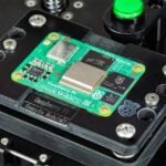
Dr. Ajith Kumar of the Inter-University Accelerator Centre, New Delhi recently got in touch with us to share his progress on interfacing the next revision of the expEYES device with the Raspberry Pi. The expEYES (“experiments for Young Engineers and Scientists”) aims to provide a low cost platform for experimentation and education in electronics and physics. The device has 12 bit analog Input/Output, Digital I/O, time interval measurements having microsecond resolution, and several other features accessible from Python. It is packaged with a number of accessories which, with the expEYES software can be used to perform a large number of experiments. For example, the device can be used to study electromagnetic induction, the conductivity of water, to measure gravity by time of flight, alongside many other applications. It aims to enable anybody with elementary Python skills to develop new experiments in addition to the ones already documented.

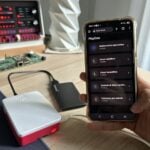
Ajith and his colleagues at the PHOENIX project have been working on low cost hardware designs to be used in education over a number of years, and all their projects have open, royalty-free designs. The pictures in this post show a new version of expEYES currently under development, aiming for an even lower price point than the original price of $25, or even less under volume production. Their team has been looking for lower-cost alternatives to netbooks for use in conjunction with expEYES, and settled on the Raspberry Pi as a solution. It connects via USB, and Ajith has also designed a version which interfaces through a serial interface using the Raspberry Pi’s GPIO pins.

Much more information about expEYES is available on the project’s website. In particular, see here for a more in-depth description of the new device and here for more pictures of the expEYES with the Raspberry Pi. The PHOENIX team
are now working on producing a larger test batch, doing further development on the micro-controller code and then continuing to seek out a path to mass production and global distribution.

Ajith is keen to hear your comments and questions, and will be monitoring and responding to the comments of this post.


38 comments
Peter
Interesting…I lived in Tamil Nadu for several years, working with a ngo there…however I have to ask…how many mAh does the board use as my raspberry pi is gonna run on batteries
Ajith Kumar
80 to 100 mA from the 5 volts supply. uC takes only 12 mA but there 10 channels of op-amps taking 20mA at +/- 8 volts.
ajith
Adam Jones
It does look very interesting! Out of interest, does it have a RTC? Just a thought because it currently appears to log via a PC and I guess that switching over to using a Pi instead means that you lose the ability to record experiment timestamps.
Rek
Unless the Pi is connected to the internet. Where the current time is readily available.
Ajith Kumar
The kind of experiments done with expEYES does not require absolute time, but the time interval between readings. In fact the uC used has built-in RTC, that I have not used.
Oli
Time for your habitual “don’t forget to resize massive photos before putting them on a website” reminder, I think :)
liz
Argh – sorry about that. (Not actually me, but a WordPress bug – and my Mac is smart and resizes the pics when looking at the post, so I hadn’t noticed.) Fixing now.
liz
Note to self: do not promise to resize pictures when the only device you’re near is a mobile phone. Sorry that took a while; had to scramble to find a machine with some image editing software on it.
YungBlood
Yea, it’s probably better to have lower res images on the home page. But I know I for one would appreciate being able to click the images, and see the full sized image.
I know I absolutely hate all these websites that say “click for larger image”, but it ends up being the exact same file at the same size!
Juan
looks nice
reiuyi
As long as the price is low and the software interface is good, nothing can go wrong really :D
I also don’t remember hearing anything about the measurements mentioned in this news article, while I did take advanced physics at high school.. Perhaps they were too expensive back then
alex
Looks great. Is it at the stage where interested parties can get hold of one or still too early?
Ajith Kumar
The current version, for PC USB, is already available. Small quantity of the new version by June end. Beyond that it all depends how many are interested.
Bjorn
This is genius! Keep up the hard work. You will be a big part of helping these kids learn at a low cost. Just genius.
Eli B.
Love it! This is what we’ve been waiting for
William H. Bell
Hi,
The boards and the concepts mentioned look very interesting. Will it be possible to self assemble these boards?
Concerning a time stamp within the DAQ setup, would it be possible to build a board with a clock chip and a FIFO? In this manner one might be able to make many samples quickly and then read them out.
Often slow control for experimental setups is required to control high voltage or high current outputs. For example, electric heaters (high current) and bias for detectors (high voltage). Some similar functionality may prove useful. A typical array of sensors might be thermocouples, humidity sensors, photo diodes, pH probe, silicon panels, GEM detectors etc..
Best regards,
Will
Ajith Kumar
At present they are hand-assembled. It does read upto 1800 samples, limited by RAM, and sends to PC for displaying. You do not need RTC for that, one of the Timers are used. It is very easy to configure it as a control system or data logger, in a way this is a spin off from a particle accelerator control system.
Marvin
When we can get is from a store? It is already months passed.
Let go with beagleboard. I cannot wait any more.
Chris
All we need now is a well priced HDMI Monitor that we can use with our RaspberryPi’s…
I have yet to find one new for under $50!
Wombat
Buy an Android Tablet and use it for a screen and keyboard (vnc or write a web page hosted on the Pi to display the resulte). Brand new 7in ones can easily be picked up for under 40 UKP and 9in ones for approx 60 low spec is fine for this purpose.
Mark Readman
Lots of exciting possibilities for signal processing and control using the Raspberry Pi and expEYES.
David Hardman
May I make a plea for future versions to include some galvanic isolation somewhere in the communication connection “string”. Apart from the safety issues the “system” ultimately connects through the TV/Monitor ground connection, that is if it has one (My 32″ LED/LCD Samsung TVs do not). Without a grounded TV you will have the permitted leakage (at some high frequency) from the switch mode power supply in the TV. This could/will play havoc with some A/D measurements.
In the lab it is very easy to put a battery operated DMM across a voltage source to measure it. The DMM is isolated so no problem. TV (or monitor)+RASPi+expEYES is not isolated.
I have several 6.5 digit DMM that are driven from the mains supply and they go to a fantastic length to:
(a) provide safety isolation from the mains (CAT II 300/600/1200 volts)
(b) negligible leakage.
OK so these are high end devices (£700 a time) but none the less the same principles apply.
TVs and monitors are not intended to be hooked up to real world experiments so there may be risks with some “el cheapo” brands.
Not to be to alarmist about it but we have a friend whose young daughter was killed by an inadequately earthed shop till.
So make it safe for the kids to use and make the measurements mean something.
Ajith Kumar
This is a very important point, we need a ground point somewhere that is connected to the actual ground potential. Galvanic isolation will not help since the concern is the entire ground floating. The power supply is the issue. If expEYES is powered by a battery, it is just a matter of putting opto-isolators on the Rx-Tx lines of the serial port, we have done this for our STM electronics board to reduce noise.
One option I can think of is to power the Rpi from a DC supply with actual earthing. The normal cell phone chargers are floating type but that is one possibility.
In fact the same amount of risk is there with using a laptop also, I
once got electric shock from the USB connector of a laptop plugged into a socket without proper earth connection.
To be very safe one can take a wire from one of the ground terminals and connect it to the earth point of the electrical socket.
Mike
David. For the low-level amateur like me, whats a ‘DMM’ – digital multimeter? (excuse my ignorance – I have a near horizontal learning curve)
David Hardman
Yep Digital Multi Meter.
I can not excuse your ignorance since you are not ignorant!! Each to their own, I am sure that you skill and expertise lies in other areas. This is my stamping ground.
Even an exponential learning curve starts off pretty flat and ends up at infinity!!
Kind regards
David H
Nico
I love the idea of RaspberryPi + expEYES
Will RS sell it as well?
Shane
I would love to get an ExpEYES here in the US. Any possibility of finding a distributor here?
Steve
Not just kids, Bjorn!
I’m looking for something similar for a humidity control system for my damp-ish basement.
I’ll need to calculate whether air pumped from the exterior at a given temp and humidity will actually absorb humidity from the basement walls for expulsion, or actually – when its temperature is dropped to that of the basement – actually condense water out and worsen the problem.
Numerous humidity and temperature sensors will be required, plus control of fans, etc. Early days, but this is a really encouraging find.
David’s point about earthing and safety is essential. Earthing, grounding, 0V refs are nothing like as simple as they sound, and safety must be the first priority
There should be very clear documentation about this with the product, preferably with clearly explained and illustrated dos and don’ts.
Best wishes,
Steve
David Hardman
Ajith
The shock you got from the laptop was probably the leakage from the laptop power supply. The output of most notebooks/laptop power supplies consists of two wires and usually neither of these are earthed. They rely on “double insulation” for their CE/UL safety approval. As they are switching power supplies they generate a high frequency leakage current across the internal safety barrier (ie the switching transformer). These currents have to be within a permitted range. This leakage current will flow through your body to ground and can cause some “tingling”. From memory the permitted current is ~2mA (I could be wildly wrong so do not rely on that figure)
How do I know this – well the same happened to me and I was responsible for shipping many thousands of note books, mild panic resulted until I had checked it out!!!!
Many monitors/TVs have similar issues.
So there is a safety issue if the leakage current is too high.
However there is another issue and that is where this current finds a way to ground/earth through the experiment. You are using a 12 bit A/D so even micro-amps of leakage can mess up the readings.
What I would humbly suggest is that you were to put two opto isolators in the Tx and Rx lines to the AVR microcomputer. Power the USB side of the unit from the USB host and power the rest from a separate power supply such as a wall wart with a traditional 50/60Hz transformer (you power demand is minimal) or at least one that you can insure is connected to ground/earth. That way you would remove yourself from earth leakage issues from laptop/monitor/TV power supplies.
This will probably slow the whole thing down (I do not know what baud rate you are using for the AVR) unless you use quite expensive opto isolators (10 Mbits/sec 6n317 100+ price ~0.40 GBP). They need to be quite fast as the AVR UART can not tolerate much distortion (<3%) [ 10 Mbits/ sec sounds fast but in this case you could be limited to ~<50 Kbaud once you take account of worst case rise, fall and propagation delays]
Hope that helps
BRGDS
David H
mgb
Not only a replacement for the BBC micro – but a VELA (http://www.retro-kit.co.uk/VELA/) for a new generation
david
I want this to go with my Raspberry Pi when it arrives although learning how to use it will take ages for me!
Bhagyesh
Sir, i want to interface temperature sensor to the expEYES ,i cant interface it directly so pls tell me how to interface.tell me the ckt diagram.
Ajith
http://expeyes.in/temperature-sensors
shows howto use LM35 temp sensor.
Using PT100 is given in the user manual, http://expeyes.in/sites/default/files/Documents/eyesj-a4.pdf
Ajith
expEYES Junior USB version has been tested with Raspberry Pi. It now works perfectly fine.
http://expeyes.in/sites/default/files/Experiments/rpi-eyes.png
Olivier
Hi,
Is expEYES RoHS compliant ? Or is planned to be ?
Thanks
JamesH
This is a pretty old blog post, it’s likely no-one is monitoring it any more – I suggest you approach the people behind the project directly.
A.K.Jain
Dear Sir,
Here at physics department we are interested to introduce for M.Sc students. We have your expeye kit and Rpi board and 12″ LCD. I have downloaded OS and display is OK.
I need to know port pins to be used for interfacing Rpi with expeye kit.
liz
I don’t think this post is being monitored any more by the expEYES team: could you please leave your requests in our forums at http://www.raspberrypi.org/phpBB3?
Comments are closed