Build an internet radio
This tutorial features in Raspberry Pi Press’ book, Simple electronics with GPIO Zero. Updated for the latest Raspberry Pi devices, this book has all the info you need to start creating electronic projects using Raspberry Pi’s GPIO pins. Coded in Python with the GPIO Zero library, projects include LED lights, a motion-sensing alarm, a rangefinder, a laser-powered tripwire, and a Raspberry Pi robot.
In Raspberry Pi Official Magazine #167, we used a trick with a capacitor to get a reading from an analogue sensor. The best — and most reliable — way for Raspberry Pi to detect analogue inputs is by using an analogue-to-digital converter (ADC) chip, such as the MCP3008, which offers eight input channels to connect sensors and other analogue inputs. This not only eliminates the need for the capacitor, but it allows you to get more precise and instant readings across the entire range of the sensor’s outputs.
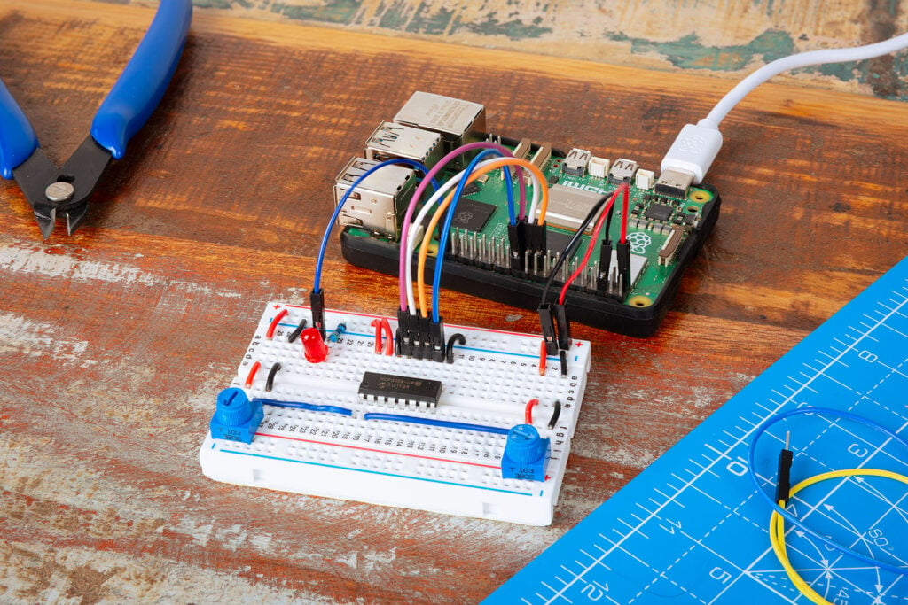
In this tutorial, we’ll hook up a potentiometer to an MCP3008 to control the brightness of an LED by turning the knob. We’ll then add a second potentiometer and create an internet radio, using the two potentiometers to switch the station and adjust the volume.
Enable SPI
The analogue values from the ADC chip will be communicated to the Raspberry Pi using the SPI protocol. While this will work in GPIO Zero out of the box, you may get better results if you enable full SPI support. First, make sure the Python spidev package is installed (it should be by default). Open a terminal window and enter:
$ sudo apt install python3-spidevNext, click the Raspberry Pi menu, choose Preferences, and open the Control Centre, then enable SPI in the Interfaces section. Click OK and reboot your Raspberry Pi. You can also use the command-line tool by running sudo raspi-config from the command prompt, going to Interface Options, enabling SPI, and rebooting your Raspberry Pi.
Connect the ADC
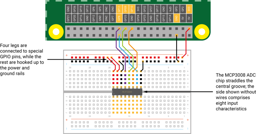
As usual, you need to turn off the Raspberry Pi while creating the circuit. As you can see from Figure 1, there’s quite a lot of wiring required to connect the MCP3008 ADC to Raspberry Pi’s GPIO pins.
First, place the MCP3008 in the middle of the breadboard, straddling its central groove. Now connect the jumper wires as in the diagram. Two go to the ‘+’ power rail, connected to a 3V3 pin; two others are connected to a GND pin via the ‘–’ rail. The four middle legs of the ADC are connected to GPIO 8 (CE0), 10 (MOSI), 9 (MISO), and 11 (SCLK).
Read the value
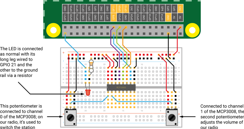
With the ADC connected to Raspberry Pi, you can wire devices to its eight input channels (numbered 0 to 7). Here, we’ll connect the first (leftmost) potentiometer, which is a variable resistor: as you turn its rotary knob, Raspberry Pi reads the voltage (from 0V to 3.3V). We can use this for control of other components, such as an LED. As shown in Figure 1, connect one outer leg of the potentiometer (bottom-left) to the ‘+’ power rail, the other side to the ‘–’ ground rail, and the middle leg to the first input of the MCP3008: channel 0.
We can now read the potentiometer’s value in Python. Create a new file, then save the following code as test_pot.py, and run it.
from gpiozero import MCP3008

pot = MCP3008(channel=0)

while True:

    print(pot.value)
At the top we import the MCP3008 class from GPIO Zero, then set the pot variable to the ADC’s channel 0. A while True: loop then continuously displays the potentiometer’s value (from 0 to 1) on the screen; try turning it as the code runs to see the number change. Press CTRL+C to exit.
Light an LED
Next, we’ll add an LED to the circuit as in Figure 2, connecting its longer (positive) leg to GPIO 21, and its shorter leg via a resistor to the ‘–’ ground rail. Create a new file, enter the following code, and save the program as source_values.py.
from gpiozero import MCP3008, PWMLED

from signal import pause

pot = MCP3008(0)

led = PWMLED(21)

led.source = pot.values

pause()
The code imports the MCP3008 and PWMLED classes, as well as the signal module’s pause function. The MCP3008 class enables us to control the brightness of an LED using pulse-width modulation (PWM). We create a PWMLED object on GPIO 21, assigning it to the led variable. We assign our potentiometer to channel 0, as before. Finally, we use GPIO Zero’s clever source and values system to pair the potentiometer with the LED, to continuously set the latter’s brightness level to the former’s value. Run the code and turn the knob to adjust the LED’s brightness. Press CTRL+C to quit the program.
Add a second pot
If you haven’t already, add a second potentiometer to our circuit as in Figure 2, with its middle leg connected to channel 1 of the MCP3008. We’ll now use both potentiometers to control our LED’s blink rate. In Thonny, create a new file, enter the following code and save it as two_pots.py.
from gpiozero import MCP3008, PWMLED

pot1 = MCP3008(0)
pot2 = MCP3008(1)
led = PWMLED(21)
while True:
    print(pot1.value, pot2.value)
    led.blink(on_time=pot1.value)
off_time=pot2.value, n=1, background=False)
Here, we create two separate pot1 and pot2 variables, assigned to the ADC’s channels 0 and 1 respectively. In a while True: loop, we then print the two values on the screen and make the LED blink, with its on and off times affected by our two potentiometers. Run the code and twist both knobs to see how it changes.
Install VLC
We’ll use the same circuit to create a simple internet radio, with one potentiometer used to switch the station and the other to adjust the volume. If it’s not installed by default, you’ll need to install the VLC media player to be able to play M3U internet radio streams. Open a terminal window and enter:
$ sudo apt install vlcMake the radio
Create a new file, enter the code shown in the radio_new.py listing above, and save it under that name.
At the start, we import the MCP3008 class, along with Popen, run, and time; Popen will enable us to start and stop VLC. We create variables for the station and volume dials, on ADC channels 0 and 1 respectively. We then assign variables to two radio stream URLs (we’ve used SomaFM Groove Salad and Indie Pop in this example).
Next, we create a couple of functions. The first, set_volume, uses wpctl (the command-line control tool for WirePlumber, the PipeWire session manager) to control the volume. The second, change_station, includes an if condition so it only triggers when the station set by the first potentiometer position is different from the currently selected one (current_station). If so, it stops the current stream and starts playing the new one, before reassigning the current_station variable to it.
Finally, in a while True: loop, inside a try … except block, we read each potentiometer in turn and use if conditional statements to call the related functions, set_volume and change_station, when required.
Run the code and try turning both potentiometers to switch the station and adjust the volume. To keep things simple, we’ve only used two radio stations in this example, but you could easily add more, adjusting the station.dial.value thresholds accordingly.
Thanks to the try … except block, pressing CTRL+C stops the radio stream before exiting the program.
Simple electronics with GPIO Zero

This tutorial features in Raspberry Pi Press’ book, Simple electronics with GPIO Zero. Updated for the latest Raspberry Pi devices, this book has all the info you need to start creating electronic projects using Raspberry Pi’s GPIO pins. Coded in Python with the GPIO Zero library, projects include LED lights, a motion-sensing alarm, a rangefinder, a laser-powered tripwire, and a Raspberry Pi robot.


7 comments
Jump to the comment form
Andrew Beasley
The code for the two pots is not correct – it is just a duplicate of the first pot read code.
Raspberry Pi Staff Ashley
Whoooopsie poopsie. Fixed it now. (I think). Thanks Andrew!
Andrew Beasley
Thanks – that makes more sense :-)
Brian
How do you get VLC to start on boot up?
DistroEx
“Create a new file, enter the code shown in the radio_new.py listing above,…” There is no radio_new.py listing above. If one wants to see it, you have to go to the Github site given under the “Download the full code” link and navigate to ch09 there.
DeeJay
“Create a new file, enter the code shown in the radio_new.py listing above”
There is no listing of ‘radio_new.py’ above. Or anywhere else in the article.
The ‘two_pots.py’ listing looks ‘broken.’ The off_time assignment is outwith the while loop so will never be executed, and it has mismatched parentheses.
darmco
The MCP3008 is a great choice when you need reliable analogue readings from a Raspberry Pi. Using SPI also makes the setup much more practical for projects where several analogue inputs need to be monitored at the same time.