Animate a Halloween skeleton — Raspberry Pi Book of Making 2027
Not since the seminal 1993 film Hocus Pocus has there been a more iconic book than Raspberry Pi Book of Making 2027, and we thought it timely to share this project from its pages, which are packed with our favourite maker projects from the past year. You can get your copy at an introductory price of £9.99, but for now, let’s animate a Halloween skeleton with a $4 Raspberry Pi Pico.

As October draws close, the veil between the worlds of the living and the dead grows thin, allowing spirits to cross. At least, that’s what watching too many horror/comedy films has taught us. Since the real world is rarely as interesting as Hollywood depicts, we’re not going to rely on the dead rising up, and give Halloween a helping hand by creating our own animated skeleton. You can build your own by following along, or adapt the techniques to animate whatever spooky (or not spooky) decorations you like.
Our build starts with a 90cm glow-in-the-dark skeleton that we purchased from AliExpress. The key part of this build relies on it being a ‘2D’ skeleton where all the joints move in the same plane. There are some 3D skeletons available that are more anatomically accurate, but also harder to animate. Unfortunately, it can be a little hard to work out from the listing whether it’s a 2D or 3D skeleton, but if it’s 90cm, glow-in-the-dark, and about £3, then it should be the right one.
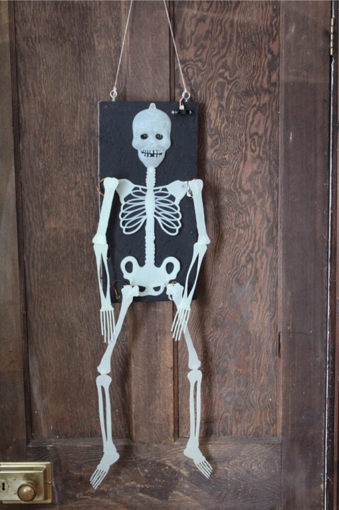
The skeleton came as ten separate parts: two for each limb, one for the body, and one for the head. We’re going to add control to the hip and shoulder joints, meaning that our skeleton can perform a few moves. The knees and elbows we’ll leave loose to flail around.
Before we get to all that though, we need a few additional parts. The skeleton is very flimsy, so we need a firm backing that we can place it on to keep everything in place. We used Oriented Strand Board (more commonly known as OSB) because we happened to have some available, but plywood would also work well. It needs to be at least 45 × 21cm, though if it’s bigger, that’s fine (and might protect your skeleton a bit more). We painted ours black to blend into the dark night.
For the motion, we used servos. Servos are a little like motors in that you send a signal to make them turn, but unlike motors, they are used for turning a particular amount and usually operate a range of about 180 degrees. You send the servo a signal to let it know the angle you want, and it turns to that angle.
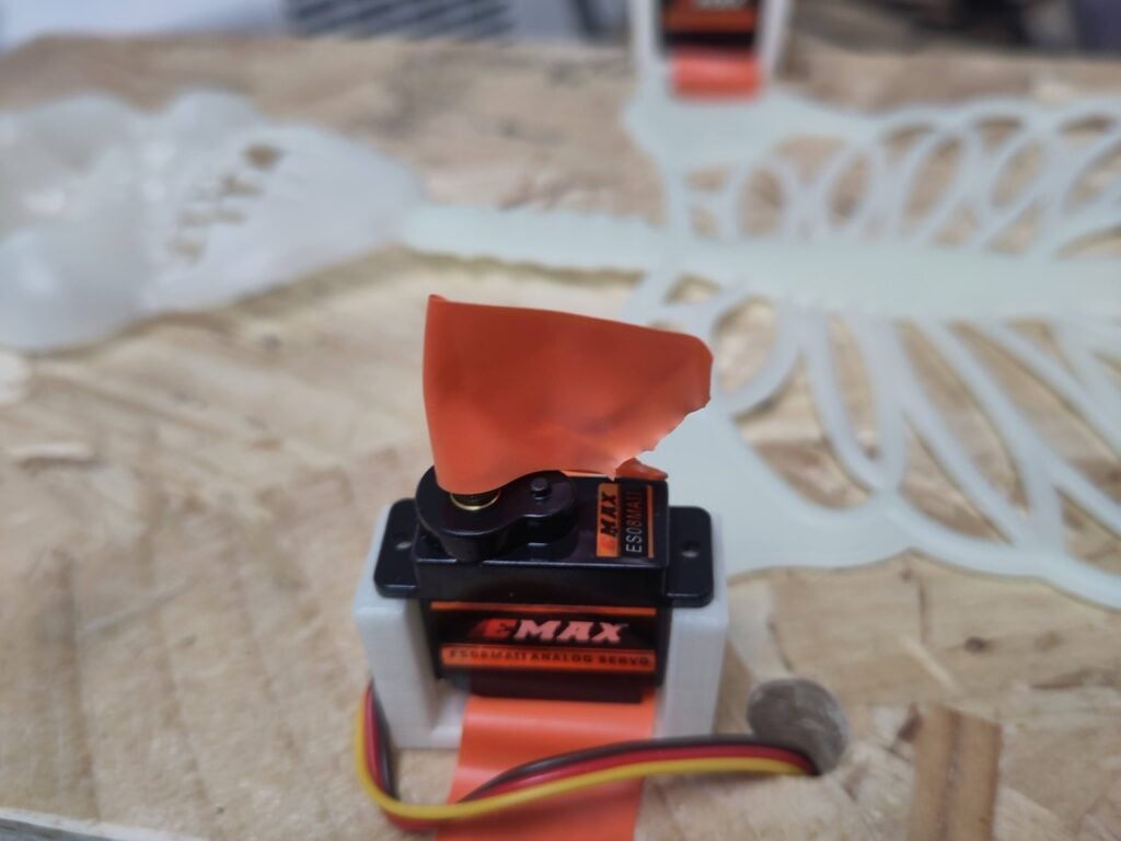
Servos come in different sizes and strengths, and we opted for 9g servos, which are just about strong enough for this. If you use anything bigger, you might find that they draw too much current, so we’d recommend sticking with little ones unless you want to add an external power supply.
We wanted our skeleton to react to people around it, so we added a distance sensor to detect when someone is close to it.
Finally, we need a controller to make everything do what we want it to. A Raspberry Pi computer will do the job, but for simplicity, we’ve used a Raspberry Pi Pico. Ours is a Raspberry Pi Pico W, but we’re not using the wireless interface, so any model should do just fine.
You’ll also need a few 3.5mm-wide screws that are smaller than your board is thick, some mounting hardware, and a cable tie.
Bare bones
Our skeleton came with moveable joints with a pin-and-socket connector. Our first thought was to keep these as hinges and then hook up an actuator to the limbs to pull them into the position we want (like making a puppet). However, we found that the flimsy plastic of the skeleton had a habit of twisting rather than rotating properly at the joint, so we needed a different plan.
The first step is to disconnect the limbs from the skeleton — they should simply pop out. We’re not going to join our skeleton directly, but rather have the servos mounted to the limbs and held in place near the joint on the main body.
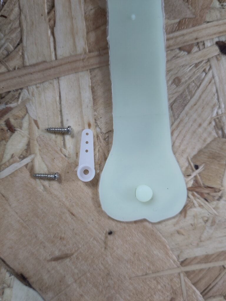
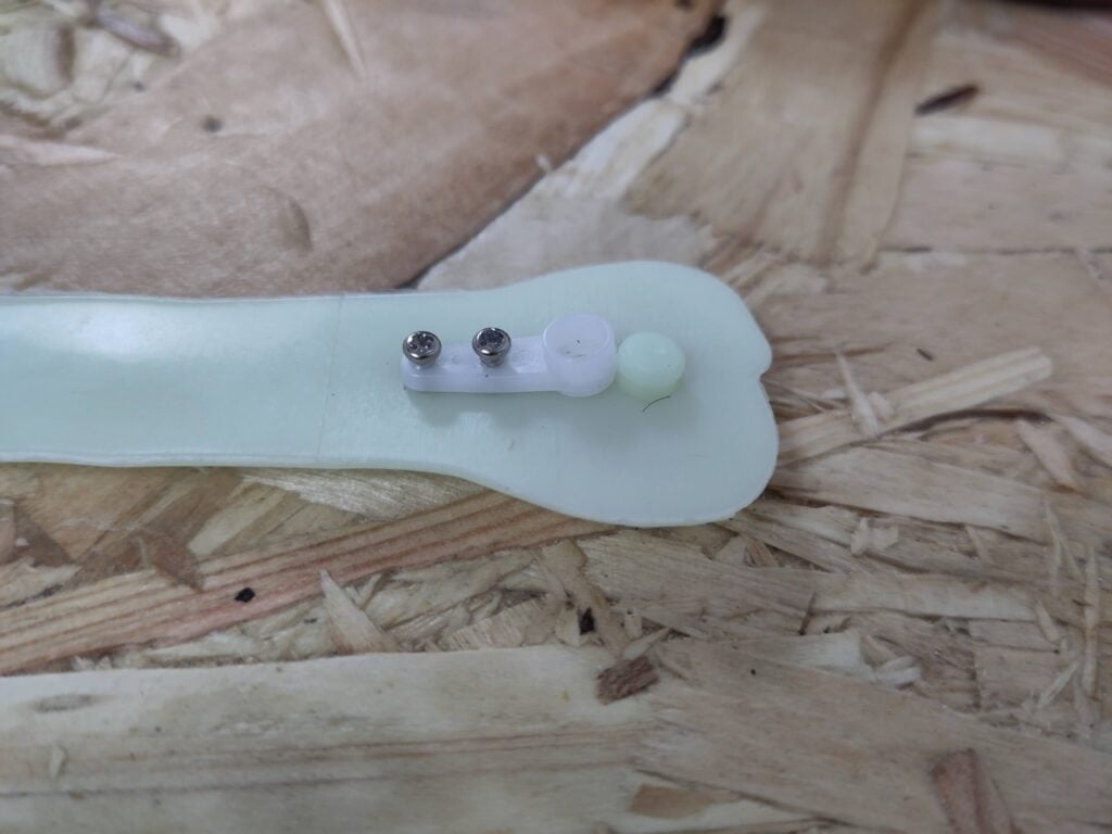
We now need a way of attaching a servo to each limb. Servos have a press-fit drive shaft that connects tightly to ‘horns’, and you usually get a selection of different-shaped horns with your servo. We used the single horn and screwed it close to the original joint.
Your servos should come with screws that go through the holes on the horn. The only problem with these is that they poke through the thin plastic of the skeleton and could scratch someone who gets too close. You can use a blob of hot glue or attach a small bit of plastic or wood to the end of the screws if you’re worried about this.
Once you have the horns attached to each limb, you now need to worry about the other side of the servos. Servos do have mounting screws, but these are usually higher up the servo, designed for a recess, so we need some form of mount to hold them in place.
If you have access to a 3D printer, then the easiest option is to print one. We used this one, but depending on your servo, you might need to use a different option. The important thing is that it holds the servo vertically.
If you don’t have access to a 3D printer, it should be possible to create a hole in your backing wood — either by chain-drilling or by drilling a starter hole and using a jigsaw — then mount the servo in there (perhaps with a liberal amount of hot glue).
Once you have your servo mounts, you should have all the key pieces of your motion-control hardware.
Eye lights
It’s well established in cinema that scary things have red eyes. We’re not really sure why this is, since the only thing this author has ever seen with red eyes was an albino rabbit, and that little ball of fluff was the least scary thing in existence. However, since that is the established trope, our skeleton should have red eyes.
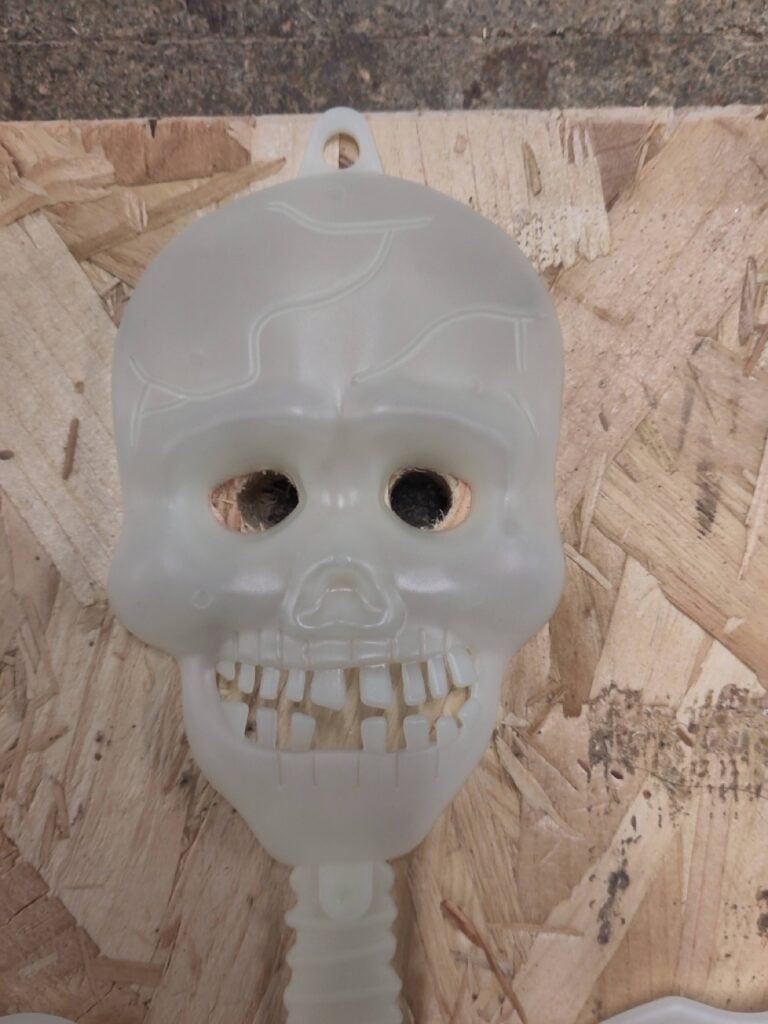
There are a couple of options for this: we could use red LEDs, or we could use RGB LEDs and just neglect two of the three colours. Although the latter option might seem a bit wasteful, it simplifies the build a bit and gives us options for the future, so we’ll go with it. The specific LEDs we’ll use are 12mm WS2811 LEDs. These come in chains (usually of 50) running at either 5V or 12V. We want the 5V version, and we just need two of the LEDs, but we can cut these from a chain.
Dark as the night
The physical setup of the skeleton is based around the back board. This should be a rectangular sheet of engineered wood strong enough to hold everything in place. The skeleton comes with a mounting hole at the top, and you can also use the holes from the shoulder and hip joints to screw it down securely.
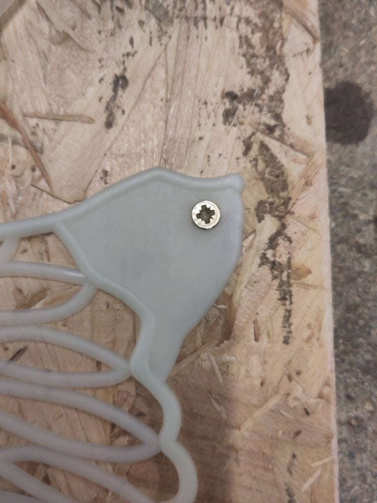
Additionally, it’ll need 12mm holes in the eyes for the LEDs, and 10mm holes near each joint to allow the wires from the servos to be tidied out the way.
At this point, you might also want to paint the board black so the skeleton stands out.
Zero in
We’re now ready to attach the servos, but before we do this we need to set up the electronics a bit. Servos don’t rotate a full turn. Typically, they can turn about 180 degrees. Because of this, we have to know their position before we attach the arms and legs, otherwise we might not be able to rotate them into the correct position once they are attached. So, before we can continue with the physical build, we need to wire them up and rotate them into a known position.
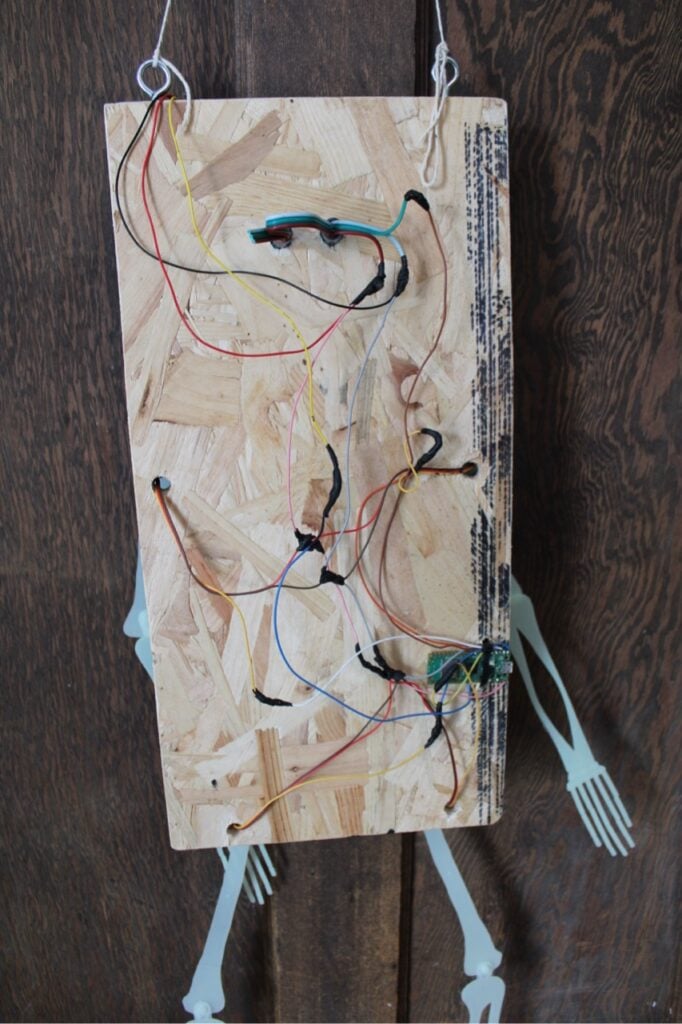
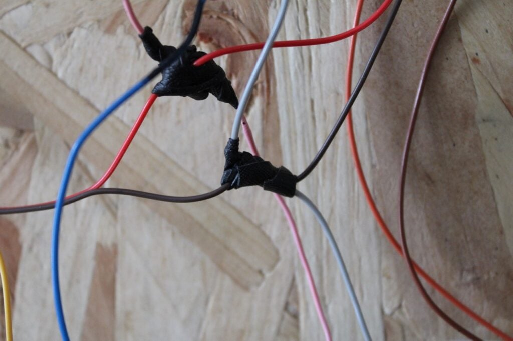
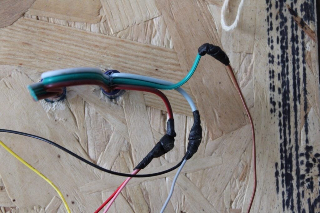
We’ve got four servos, but they all need to be connected to the same power pins, so some creative wiring is needed. We wired it up as shown above. This requires soldering a four-way joint. You might need to solder some extra bits of wire onto the servo wires for extensions. Make sure that the servo wires go through the holes in the board to allow the servos to be mounted properly before they’re soldered together.
Once you’ve got the servos soldered up, you can find out what state they’re in. For this, we’ll need to program Raspberry Pi Pico.
Code configuration
If you’ve not used MicroPython before, take a look at the getting started guide. The short version of this is that you need to install Thonny and then install the MicroPython firmware on your Raspberry Pi Pico. At this point, you can use the Thonny IDE to write code and send it to the microcontroller board.
You’ll also need the servo library. Using Thonny’s file manager, create a folder called servo on your Raspberry Pi Pico and copy the __init__.py and __main__.py files into it.
Attach something easily removable to the drive shafts (we used flags made of electrical tape) and run the test code below.
import time

from servo import Servo

left_hip = Servo(pin_id=0)

left_shoulder = Servo(pin_id=1)

right_hip = Servo(pin_id=2)

right_shoulder = Servo(pin_id=3)

servos = [left_hip,left_shoulder, right_hip, right_shoulder]

down_angle = [180,180, 0,0]

up_angle = [90,90,90,90]

while True:

    print("down")

    for i, servo in enumerate(servos):

        servo.write(down_angle[i])

    time.sleep(2)

    print("up")

    for i, servo in enumerate(servos):

        servo.write(up_angle[i])

    time.sleep(2)
This alters between two different states: down and up. You should be able to adjust the flags so that down points down and up points at 90 degrees. This then tells you the angle you want to add the limbs at. In other words: once the flags are adjusted so they point in this direction, you can then add the limbs so they point in the same direction as the flags.
However, before we add the limbs, let’s add the final two parts of the electronics: a distance sensor and the LEDs.
There are a few options you could use to detect people. Passive infrared (PIR) sensors are a popular choice for triggering things like this, and one could certainly work in this project. However, they can be triggered very easily, and we prefer our skeleton to activate when someone gets closer.
It is possible to do something advanced with a camera and some form of machine-learning person detector, but these don’t always work well in the dark (particularly with changing light), so aren’t a great choice for night-time installations.
We’ve used a plain distance sensor. Specifically, a Sharp GP2Y0A02YK. This outputs an analogue voltage that corresponds with the closest thing to it (up to about 1.5m). It’s easy to work with, as we just have to hook it up to an analogue input. The one downside is that there’s quite a small field of view, so it doesn’t always trigger when you hope it would. Our search for a perfect person detector continues, but for now, this works well enough.
Wiring the sensor requires 5V, ground (both of which are built off the power chain for the servos), and an analogue input (we used A0 on GPIO 26).
The final part of the electronics is the LEDs for the eyes. These should come as a string, and you’ll need to cut two off. Each LED has six wires attached to it: two for power, two for ground, one for data-in, and one for data-out. This means that the string has three wires for input and three for output, but it’s not always obvious which end of the string is input and which is output. If you look very closely at the string, you should see an arrow on the PCB that points to the data-out line. The data-in line is opposite this. Power should be red and ground should be white.
Power requires 5V, so along with the distance sensor, that’s another two devices that need to be connected to the single VBUS connector on Raspberry Pi Pico, so you’ll need to extend the chain of wires built off this pin. We connected the data-in to GPIO 5, but any should work.
It might be tempting to add more than two LEDs to the display. You could certainly add more to act as lightning or any other effect. However, we recommend that if you do this, you add an additional power supply, as we’re stretching the USB power supply about as far as we should really push it.
Eye, eye
Now let’s finish up the assembly. The LEDs push into their holes — just. Although they require 12mm holes, they have barbs to hold them in place. With a bit of force, you should be able to push them in far enough for them to hold in place. If you can’t, then the best option is to use a 12mm drill bit and wiggle it in the hole to enlarge it slightly.
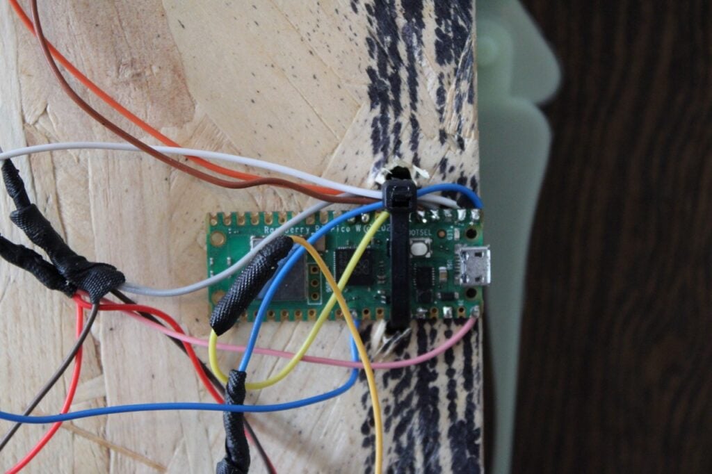
Mounting Raspberry Pi Pico is a bit tricky, as it’s hard to find wood screws that fit through the M2.5 holes. The most secure option is to use a case with mounting points. However, a quicker and easier method is to drill two 5mm holes, one either side of your Raspberry Pi Pico, and use a cable-tie to hold it in place. It’s a bit of a hack-y solution, but good enough for a prop that’s going to be out for a few days a year. Just make sure that the USB port is at the edge of the backing so you can plug in a cable, and also make sure that the cable tie doesn’t go over the BOOT button.
Finally, you need a way of mounting your skeleton, and this will depend a little on where you want to display it. We fastened two eye screws into the top of the backing, which will allow us to hang it up. You could also drill through the backing and screw it into place, or just G-clamp where you want it to be.
Ready for action
That’s our skeleton fully set up and working; let’s program it. The following MicroPython code will test out all the components. It’ll use the distance sensor to trigger the eyes lighting up and the limbs moving.
from machine import Pin, ADC

from time import sleep

import neopixel

from servo import Servo

left_hip = Servo(pin_id=0)

left_shoulder = Servo(pin_id=1)

right_hip = Servo(pin_id=2)

right_shoulder = Servo(pin_id=3)

servos = [left_hip,left_shoulder, right_hip, right_shoulder]

down_angle = [0,0, 180,180]

up_angle = [90,90,90,90]

np = neopixel.NeoPixel(machine.Pin(4), 2)

distance = ADC(Pin(26))

legs_down = True

while True:

    print(distance.read_u16())

    if distance.read_u16() > 10000:

        np.fill((0,255,0))

        np.write()

        dancing = True

    else:

        np.fill((0,0,0))

        np.write()

        print("off")

        dancing = False

    if dancing:

        if legs_down:

            legs_down = False

            for i, servo in enumerate(servos):

                servo.write(down_angle[i])

        else:

            legs_down = True

            for i, servo in enumerate(servos):

                servo.write(up_angle[i])

    sleep(1)
If you save this to your Raspberry Pi Pico as main.py, it will launch automatically when you power up the board, so you just need to connect a USB power supply (capable of at least 2A) and your skeleton should activate.
At this point, we have a fully working person-activated skeleton, but there’s one bit that you might need to change.
Let’s work out the right distance value to trigger the action. This will depend on the place you want it physically set up. If it’s in a corridor, alleyway, or other area where there’s a wall opposite, then you might need to make the number higher so that it’s not triggered by the wall. Other than this, it’s really up to you how close you want people to get before it activates. The closer people are, the scarier it might potentially be to them, so you might want to take this into account, especially if there are likely to be young children.
In either case, the number you need to change is the one in this line:
if distance.read_u16() > 10000:As the method suggests, it’s an unsigned 16-bit number, so the maximum possible value is 65,535.
That’s our animated Halloween skeleton set up and ready to scare the local trick-or-treaters.
New from Raspberry Pi Press: Raspberry Pi Book of Making 2027
Each month in Raspberry Pi Official Magazine, we strive to bring you an eclectic mix of DIY electronics, 3D prints, microcontrollers, sensors, motors, and other fun things to do with Raspberry Pi. This year, we’ve once again taken a selection of our favourite builds and gathered them in one place: the Raspberry Pi Book of Making 2027.

Order a copy from our store for just £14 £9.99 (introductory price). It’s also available from online retailers such as Amazon US and UK, and from other booksellers who have exceptional taste in books. If you’re interested in an electronic version, we’ve got several ways you can get your hands on a PDF or ePUB.
After adding this new book to your shopping cart, be sure to check out the many other books we offer in our online shop.




No comments
Jump to the comment form