$ ssh <username>@pi-webcam.localPlug-and-play Raspberry Pi USB webcam
All tutorials
note
This tutorial was written for Raspberry Pi OS Bullseye and has not yet been updated for our latest operating system, Bookworm. There have been major changes between these two OS releases, including changes to networking. You can still follow this tutorial, but you will have to download and install the "legacy" version of the operating system.
Many of us have become all too familiar with Zoom, Teams, Skype, and countless other video calling applications in recent years. They’re essential to see our coworkers when we work remotely. At times, they have been the only way to see our loved ones. Unfortunately, many laptops and USB webcams use cameras that are, at best, mediocre.
This tutorial helps you create a USB webcam using a Raspberry Pi and a Raspberry Pi camera. Plug it into any Mac, Windows, or Linux computer to use it as a video camera.
Supplies
-
Raspberry Pi
-
cable to connect your Raspberry Pi to your computer for power and data
-
microSD card
-
adapter to connect your microSD card with your usual computer
-
Raspberry Pi camera
-
Raspberry Pi camera cable
-
Raspberry Pi case with camera mount
-
laptop mount or tripod
For the initial SD card setup, you will need:
-
Another computer connected to your network. We’ll refer to this as your usual computer to distinguish it from the Raspberry Pi computer you are setting up as a webcam.
Choose the right Raspberry Pi
For this tutorial, we’ll use a Raspberry Pi Zero 2 W. Since this model supports USB On-The-Go (OTG), we can use one cable for both power and data.
Choose the right camera
For this tutorial, we’ll use a Raspberry Pi Camera Module 3.
You’ll also need a cable to connect your camera with your Raspberry Pi. For all Raspberry Pi Zero models, we recommend the Raspberry Pi Camera Cable.
Choose the right case
A Raspberry Pi case with a camera mount keeps your webcam safe from everyday wear and tear.
You could 3D print these Raspberry Pi Zero 2 W case files. This case requires a combination of M2 and M2.5 nylon hex spacers for assembly.
There are also many third-party Raspberry Pi cases available on the market, and some include a camera mount.
Since you’ll connect the entire setup to your computer as a webcam, you should also consider a laptop mount or tripod to make it easier to set up your webcam.
Configure your Raspberry Pi
To begin, follow the Getting Started documentation to set up your Raspberry Pi. For your operating system, choose Raspberry Pi OS (Other) > Raspberry Pi OS (Legacy) Lite to run headless (without a mouse and keyboard).
During the OS customisation stage, edit settings as follows:
-
Enter a hostname of your choice (we suggest
pi-webcamfor this tutorial) -
Enter a username and password; you’ll need these later to authenticate
-
Check the box next to Configure wireless LAN so your Pi can automatically connect to Wi-Fi
-
Enter your network SSID (name) and password; you can find these in your Wi-Fi settings or on a sticker on your router
-
-
Check the box next to Enable SSH so we can connect to the Pi without a mouse and keyboard
Remotely connect to your Raspberry Pi
SSH allows you to wirelessly connect to your Raspberry Pi, eliminating the need for a keyboard and mouse. It’s perfect if your Raspberry Pi is located in a hard-to-reach location, like behind a train times display.
note
To SSH into the Raspberry Pi, you’ll use the hostname you set in Imager. If you have issues connecting using this method, you may want to use the Raspberry Pi’s IP address instead.
For more information about finding your IP address and remote accessing your Raspberry Pi, see the remote access documentation.
Connect via SSH
Open a terminal session on your usual computer. To access your Raspberry Pi via SSH, run the following command, replacing <username> with the username you chose in Imager:
The first time you do this, confirm that you want to connect. When asked, use the password you created in Raspberry Pi Imager:
$ ssh <username>@pi-webcam.local
The authenticity of host 'pi-webcam.local (fd81:b8a1:261d:1:acd4:610c:b069:ac16)' can't be established.
ED25519 key fingerprint is SHA256:s6aWAEe8xrbPmJzhctei7/gEQitO9mj2ilXigelBm04.
This key is not known by any other names
Are you sure you want to continue connecting (yes/no/
[fingerprint])? yes
Warning: Permanently added 'pi-webcam.local' (ED25519) to the list of known hosts.

<username>@pi-webcam.local's password:
Linux pi-webcam 6.1.21-v8+ #1642 SMP PREEMPT Mon Apr  3 17:24:16 BST 2023 aarch64

The programs included with the Debian GNU/Linux system are free software;
the exact distribution terms for each program are described in the
individual files in /usr/share/doc/*/copyright.

Debian GNU/Linux comes with ABSOLUTELY NO WARRANTY, to the extent
permitted by applicable law.
Last login: Thu Oct 26 09:41:00 2023
<username>@pi-webcam:~ $
Now that you’ve connected to your Raspberry Pi, run two commands to make sure that all of your packages are up to date:
$ sudo apt update
$ sudo apt full-upgrade
Once the package update commands finish running, reboot your Raspberry Pi to allow all changes to take effect:
$ sudo rebootRunning this command will disconnect you from the Raspberry Pi SSH session. Wait a few seconds for your Raspberry Pi to reboot, and enter the ssh connection command again to reconnect to your device.
tip
On most terminals, press the Up arrow key, then the Enter key to re-run the most recent command.
Set up and install required software
Now that your Raspberry Pi is up and running, let’s instruct your Raspberry Pi to act as a OTG (On-The-Go) USB device when attached to another computer. We’ll do this by adding to the /boot/firmware/config.txt file. Append to the file with the following command:
$ echo "dtoverlay=dwc2,dr_mode=otg" | sudo tee -a /boot/firmware/config.txtOur next step is to install a few prerequisite programs:
$ sudo apt install git meson libcamera-dev libjpeg-devMeson is an open source build system that we’ll use to put together the camera software later. Libcamera and Libjpeg help your Raspberry Pi use your camera. Type y to confirm that you’d like to install the programs.
Next, download the UVC gadget software. This helps your Raspberry Pi stream video over USB:
$ git clone https://gitlab.freedesktop.org/camera/uvc-gadget.gitNavigate to the downloaded folder:
$ cd uvc-gadgetWe now need to make, build, and install the software with the following commands:
$ make uvc-gadget
$ cd build
$ sudo meson install
$ sudo ldconfig
The last command, ldconfig, typically runs after installing new libraries or updating existing ones. It helps Raspberry Pi OS properly link to new libraries.
Next, create a script that will run each time your Raspberry Pi is powered on in order to set everything up. Use the nano text editor to create a bash script:
$ sudo nano ~/.rpi-uvc-gadget.shCopy and paste the following code into the text editor:
#!/bin/bash

# Variables we need to make things easier later on.

CONFIGFS="/sys/kernel/config"
GADGET="$CONFIGFS/usb_gadget"
VID="0x0525"
PID="0xa4a2"
SERIAL="0123456789"
MANUF=$(hostname)
PRODUCT="UVC Gadget"
BOARD=$(strings /proc/device-tree/model)
UDC=`ls /sys/class/udc` # will identify the 'first' UDC

# Later on, this function is used to tell the usb subsystem that we want
# to support a particular format, framesize and frameintervals
create_frame() {
	# Example usage:
	# create_frame <function name> <width> <height> <format> <name> <intervals>

	FUNCTION=$1
	WIDTH=$2
	HEIGHT=$3
	FORMAT=$4
	NAME=$5

	wdir=functions/$FUNCTION/streaming/$FORMAT/$NAME/${HEIGHT}p

	mkdir -p $wdir
	echo $WIDTH > $wdir/wWidth
	echo $HEIGHT > $wdir/wHeight
	echo $(( $WIDTH * $HEIGHT * 2 )) > $wdir/dwMaxVideoFrameBufferSize
	cat <<EOF > $wdir/dwFrameInterval
$6
EOF
}

# This function sets up the UVC gadget function in configfs and binds us
# to the UVC gadget driver.
create_uvc() {
	CONFIG=$1
	FUNCTION=$2

	echo "	Creating UVC gadget functionality : $FUNCTION"
	mkdir functions/$FUNCTION

	create_frame $FUNCTION 640 480 uncompressed u "333333
416667
500000
666666
1000000
1333333
2000000
"
	create_frame $FUNCTION 1280 720 uncompressed u "1000000
1333333
2000000
"
	create_frame $FUNCTION 1920 1080 uncompressed u "2000000"
	create_frame $FUNCTION 640 480 mjpeg m "333333
416667
500000
666666
1000000
1333333
2000000
"
	create_frame $FUNCTION 1280 720 mjpeg m "333333
416667
500000
666666
1000000
1333333
2000000
"
	create_frame $FUNCTION 1920 1080 mjpeg m "333333
416667
500000
666666
1000000
1333333
2000000
"

	mkdir functions/$FUNCTION/streaming/header/h
	cd functions/$FUNCTION/streaming/header/h
	ln -s ../../uncompressed/u
	ln -s ../../mjpeg/m
	cd ../../class/fs
	ln -s ../../header/h
	cd ../../class/hs
	ln -s ../../header/h
	cd ../../class/ss
	ln -s ../../header/h
	cd ../../../control
	mkdir header/h
	ln -s header/h class/fs
	ln -s header/h class/ss
	cd ../../../

	# This configures the USB endpoint to allow 3x 1024 byte packets per
	# microframe, which gives us the maximum speed for USB 2.0. Other
	# valid values are 1024 and 2048, but these will result in a lower
	# supportable framerate.
	echo 2048 > functions/$FUNCTION/streaming_maxpacket

	ln -s functions/$FUNCTION configs/c.1
}

# This loads the module responsible for allowing USB Gadgets to be
# configured through configfs, without which we can't connect to the
# UVC gadget kernel driver
echo "Loading composite module"
modprobe libcomposite

# This section configures the gadget through configfs. We need to
# create a bunch of files and directories that describe the USB
# device we want to pretend to be.

if
[ ! -d $GADGET/g1 ]; then
	echo "Detecting platform:"
	echo "  board : $BOARD"
	echo "  udc   : $UDC"

	echo "Creating the USB gadget"

	echo "Creating gadget directory g1"
	mkdir -p $GADGET/g1

	cd $GADGET/g1
	if
[ $? -ne 0 ]; then
		echo "Error creating usb gadget in configfs"
		exit 1;
	else
		echo "OK"
	fi

	echo "Setting Vendor and Product ID's"
	echo $VID > idVendor
	echo $PID > idProduct
	echo "OK"

	echo "Setting English strings"
	mkdir -p strings/0x409
	echo $SERIAL > strings/0x409/serialnumber
	echo $MANUF > strings/0x409/manufacturer
	echo $PRODUCT > strings/0x409/product
	echo "OK"

	echo "Creating Config"
	mkdir configs/c.1
	mkdir configs/c.1/strings/0x409

	echo "Creating functions..."

	create_uvc configs/c.1 uvc.0

	echo "OK"

	echo "Binding USB Device Controller"
	echo $UDC > UDC
	echo "OK"
fi

# Run uvc-gadget. The -c flag sets libcamera as a source, arg 0 selects
# the first available camera on the system. All cameras will be listed,
# you can re-run with -c n to select camera n or -c ID to select via
# the camera ID.
uvc-gadget -c 0 uvc.0
Press Ctrl+X, then Y, and finally Enter to save the edited file with nano.
Use the following command to make the script executable:
$ sudo chmod +x ~/.rpi-uvc-gadget.shTo execute this script every time the device boots, add to the /etc/rc.local file. Raspberry Pi OS always executes this file after boot. Edit /etc/rc.local using the following command:
$ sudo nano /etc/rc.localAdd the following command to execute our script above the exit 0 line, replacing the <username> placeholder with the username you specified in Imager:
$ /home/<username>/.rpi-uvc-gadget.sh &tip
If you’re not sure what your username is, exit
nano with Ctrl+X, then Y, and finally Enter and run the whoami command. This command outputs your username.Press Ctrl+X, then Y, and finally Enter to save the edited file with nano. The file should now look like this:
#!/bin/sh -e
#
# rc.local
#
# This script is executed at the end of each multiuser runlevel.
# Make sure that the script will "exit 0" on success or any other
# value on error.
#
# In order to enable or disable this script just change the execution
# bits.
#
# By default this script does nothing.

# Print the IP address
_IP=$(hostname -I) || true
if
[ "$_IP" ]; then
  printf "My IP address is %s\n" "$_IP"
fi

/home/<username>/.rpi-uvc-gadget.sh &

exit 0
Finally, shut down your Raspberry Pi:
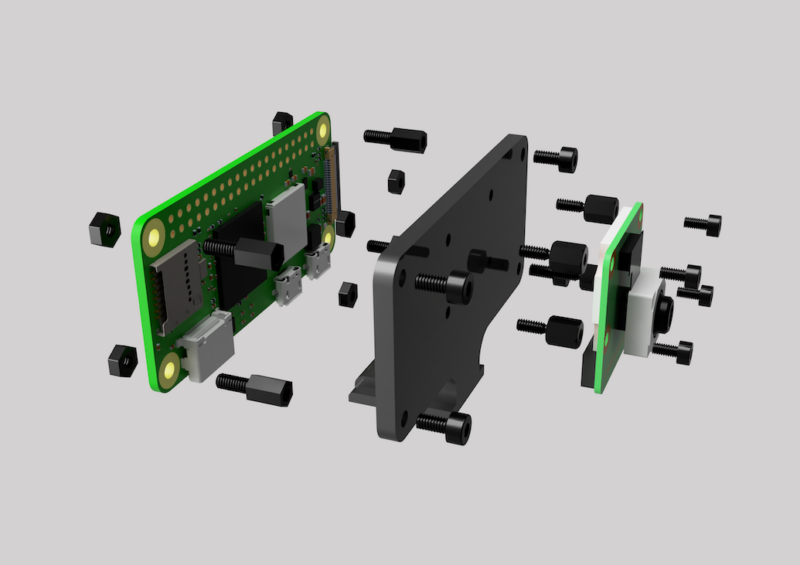
$ sudo shutdown -h nowPackage it all up in a case
Connect your camera to your Raspberry Pi with the ribbon cable (see here for how to do this).
Put your Raspberry Pi and the connected camera into your case. To assemble the case, fasten together the camera, Raspberry Pi, and 3D-printed case using M2.5 and M2 hex nylon standoffs, nuts and bolts, as this image shows:
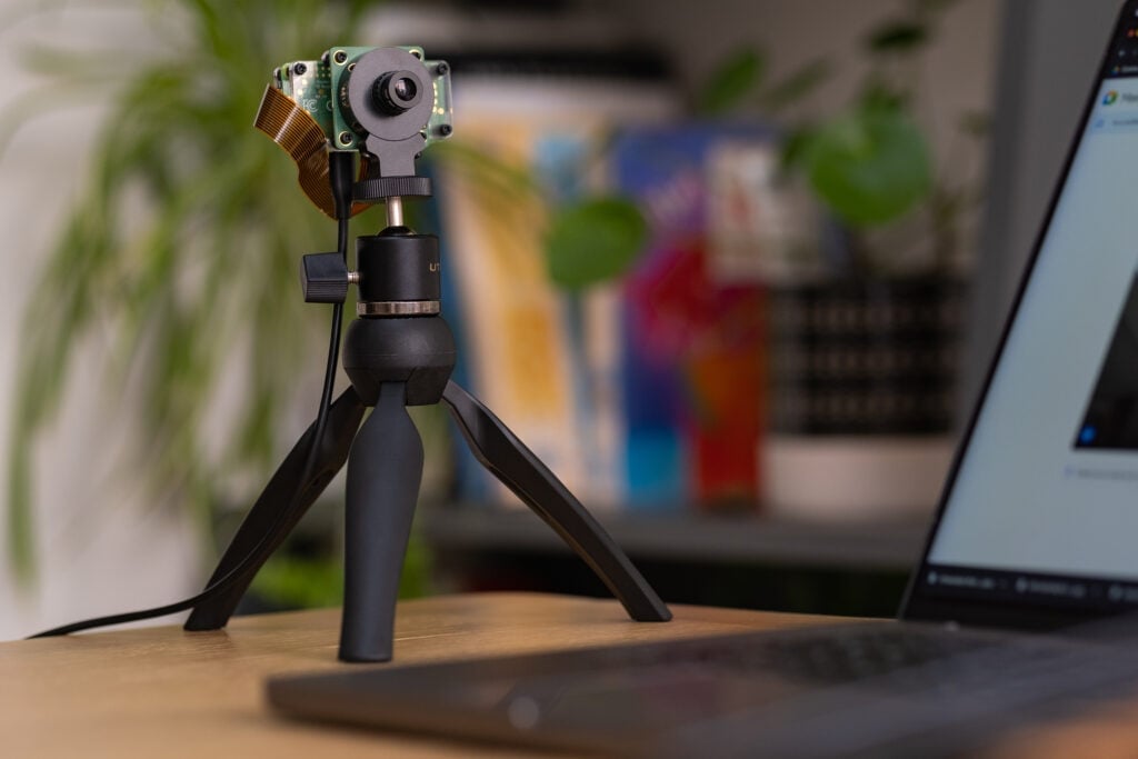
The 3D printed case fits any standard cold shoe camera mount:

Use your Raspberry Pi webcam
With your Raspberry Pi configured to run as a USB webcam anytime you plug it in to a computer, all that remains is to use it.
important
If you’re using a Raspberry Pi Zero 2 W, connect your microUSB cable to the microUSB data port on your Raspberry Pi, not the power port. The power port only supports power.
Plug your Raspberry Pi into your computer. Allow device access on any OS prompts that pop up. Open your favourite video conferencing software and start a meeting. Find your Raspberry Pi webcam in your video options, and set it as your camera. Congratulations — you’re now ready to use your new webcam for video calls!
Next steps
Looking to take your webcam to the next level? Check out these ideas to make your webcam even better.
Want to impress your friends with a crispy, high-quality camera feed? The Raspberry Pi High Quality Camera has a higher resolution and is compatible with any standard tripod:
Not happy with your webcam case? The piSight project by Max Braun uses the casing from the iconic Apple iSight. This project replaces the 25-year-old iSight’s innards with a Raspberry Pi Zero 2 W and Camera Module 3.


Check out our blog here to read all about it, and find all the necessary 3D print files available for free here.