Make a chord keyboard with Raspberry Pi Pico and CircuitPython
If you’ve ever wanted to be able to type without looking at the keyboard, this project is for you.
We’re going to make a USB keyboard you can use to enter text quickly and unobtrusively, even in the dark. The keyboard has a key for each finger, and you type by pressing down ’chords’ – combinations of different keys. There are lights in the keys to help you learn the combinations for each letter and a teaching game you can use to practice your typing skills. You can plug it into a USB port on a computer and use it as you would any other keyboard.

The PICO Chord keyboard
Figure 1 shows the device. Six illuminated keys are used to enter chords, and a four-character text display gives user feedback. The keyboard can be used to enter letters, numbers, and symbols. It has a teaching game that you can use to build your skills. It can also be used to type out its own documentation, in the form of a chart giving all the chord designs.
You can use any kind of switch in the keyboard, but this project uses the Adafruit NeoKey breakout board and individual key switches.
The keyboard is powered by a Raspberry Pi Pico device running a CircuitPython program that scans
the keys and sends them out over a USB connection to a computer.

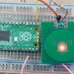
Figure 2 shows a couple of Adafruit NeoKey breakout boards connected to a Raspberry Pi Pico. The NeoKey contains a socket for a CHERRY MX-compatible key switch. It also contains a NeoPixel that can be used to illuminate the key.
If you look carefully at Figure 2, you’ll notice that there are two ground connections for each NeoKey. These are black wires at the bottom of the image. This is because a NeoKey board contains a diode that is connected in series with the key switch. This is useful if you want to use the boards in a keyboard matrix, but it slightly complicates our wiring because each key needs a ground connection for the power to the NeoPixel LED and another to bias the diode in the switch circuit.

Figure 3 shows the inside of the box. The keys are pushed into the outside of the case through square holes and the NeoKey boards are then plugged onto the back of the key inside the case. The Raspberry Pi Pico fits alongside the display to reduce the height of the case. The cables are colour-coded. Red and black wires provide the power, yellow wires transfer the signal for the NeoPixel, and the other colours are signals for the switches.
Figure 4 shows the complete circuit diagram for the keyboard. You can use different GPIO pins in your circuit, and even change the order of the LED colours by modifying the code that creates the keyboard object in the program.
keyboard = PicoChord (i2c_sda=board.GP0, i2c_scl=board.GP1,
            pixel_pin=board.GP17,
            key_switches=[
                Switch(pin=board.GP15,pixel=0,bit=1),  # control
                Switch(pin=board.GP14,pixel=1,bit=2),  # thumb
                Switch(pin=board.GP13,pixel=2,bit=4),  # index
                Switch(pin=board.GP12,pixel=3,bit=8),  # middle
                Switch(pin=board.GP11,pixel=4,bit=16), # ring
                Switch(pin=board.GP10,pixel=5,bit=32)  # little
                ])
The code above creates an instance of the PicoChord class by calling the constructor method for that class. The constructor sets the GPIO connections used for the I2C connection to the text display board, the NeoPixel display, and the individual switches. You can use this code to help you wire up the components to Pico.

The CircuitPython program and all the required libraries are available on the GitHub site for this project which you can find at here.
Chord Keyboards
The traditional QWERTY keyboard has been around for a very long time. But it does have its disadvantages. You need to use both hands to type quickly, and unless you are a skilled touch-typist, you will have to look at your hands while you’re entering text. When you use a QWERTY keyboard, you usually press one key to enter a character. The word ’chord’ is borrowed from music, when you play multiple notes together on a keyboard to make more interesting sounds. When you use a chord keyboard, you press a particular combination of keys to select a given character.
A chord keyboard can be used with one hand. Once you’ve learned the letter shapes, you can type without looking at the keyboard because your fingers never move off their ’home’ keys. A chord can be much smaller than a QWERTY device, making it more portable.

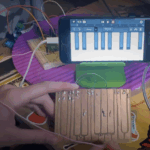
Figure 5 shows a ghostly white hand entering text on the keyboard. Chord keyboards don’t register characters when the keys are pressed. Characters are detected when the user takes their finger off the keys. This is because the keyboard can only detect that a complete chord has been entered when the user lifts their finger off one of the pressed keys. For example, you press three keys to enter a ’b’, as shown in Figure 5. These keys also form part of the letter ’m’, which is represented by four keys. The keyboard can only determine that the chord for a ’b’ has been entered when one of the three keys in the chord is released. The user must then lift all their fingers before entering the next key. The good news is that with a bit of practice, you can enter text surprisingly quickly. The keyboard contains chords for text, numbers, and a range of symbols.
The key at the far left of the keyboard is the ’control’ key. The thumb presses this key to enter chords that control the keyboard. Pressing the control key on its own will toggle the shift status of the keyboard so you can change between capital and lower case letters. When in shift mode, the keys light up yellow.

Reading the chords
The keyboard converts chords into character codes to be sent over USB to the connected computer. The first step in the conversion is to represent every chord by a unique numeric value. We do this by mapping each key in the chord onto a particular bit in that number, as shown in Figure 6. For example, the letter ’b’ that we typed in Figure 5 would be represented by 8 + 16 + 32, which gives the value 56. Each time a key is pressed, the keyboard adds the ’bit’ value of that key to a total that is stored in a variable called bits. When a key is released, the value in bits represents the chord that was entered. The program then uses a Python dictionary to look up the character that the chord represents.
self.text_decode = {
    12:'a', 56:'b', 10:'c', 14:'d', 4:'e', 30:'f', 48:'g', 34:'h',
    6:'i', 50:'j', 18:'k', 38:'l', 60:'m', 24:'n', 8:'o', 62:'p',
    40:'q', 22:'r', 16:'s', 20:'t', 32:'u', 36:'v', 54:'w', 58:'x',
    26:'y', 42:'z', 2:' ', 52:',',  28:'.'}
The code above shows the dictionary text_decode which is used to decode the keyboard chord values. The code for ’b’ is clearly indeed 56. You could use this dictionary to work out the key combinations for all the letters. Some letters, for example ‘s’, ‘e’, and ‘u’, are represented by a single key.
key = self.text_decode[bits]
The statement above uses the value in bits to access the text_decode dictionary and extract the character that the chord represents. The variable key would be set to the character that has been entered. The keyboard software contains two other dictionaries for symbols and command codes.
Once the keyboard has the key character, the next thing to do is send that character out from the keyboard over USB.
self.usb_layout.write(key)
The statement above writes out a string from the keyboard. The USB connection is managed by code from the usb_hid libraries in CircuitPython.
import usb_hid
from adafruit_hid.keyboard import Keyboard
# Import the keyboard layout description
from adafruit_hid.keyboard_layout_uk import KeyboardLayoutUK

self.usb_kbd = Keyboard(usb_hid.devices)
# Set the required keyboard layout
self.usb_layout = KeyboardLayoutUK(self.usb_kbd)
The statements above import the required libraries and then create the keyboard connection for use by the program.
Getting help
The chord for ’b’ is entered by pressing and releasing the rightmost three keys on the keyboard. We could work out the chords for the other characters by studying the text_decode dictionary above but what we really want is a document that gives the chords for every character and symbol. The best way to
get this is to generate it automatically from thetext_decode dictionary. This ensures the chord designs are only stored in one place, and if we change any of the chords or add new ones, the documentation updates automatically.
def print_key(self,symbol,bits):
    print("Printing:",symbol,bits)
    self.send_animated_text_to_keyboard(symbol)

    top_line = "        "
    bottom_line = ""
    for bit in (1,2,4,8,16,32):
        if (bits & bit) == 0:
            text="[ ] "
        else:
            text="[X] "
        if bit < 4:
            bottom_line = bottom_line + text
        else:
            top_line = top_line + text
    self.send_animated_text_to_keyboard(top_line)
    self.send_animated_text_to_keyboard(bottom_line)
    self.send_animated_text_to_keyboard("-----------------------")
The print_key function is given a symbol and a bit pattern. It prints out a tiny description of the chord for that key. It tests each bit in the bits value and selects [X] or [ ] based on whether or not that key is used in the chord for that character. The key information is added to the top or bottom line of the description depending on which bit is being processed.
self.print_key('b', 56)
The statement above would print out the chord for the character ’b’.
b [ ] [X] [X] [X]
[ ] [ ]
-----------------------
Above is the description of the chord for ’b’. The top line gives the character and the next two show which keys to press. This text is transmitted from the keyboard using the send_animated_text_to_keyboard function. This sends characters to the host computer, but also displays them on the keys on the keyboard. This means that if you want a document for all the chords, you just open an empty document, put the text cursor inside the document, and press the Help command. You can then watch as the keyboard magically types its documentation for you.

Figure 7 gives the chord designs for text entry. There are also tables for number, symbol, and command modes. You can download them from the GitHub site for the project.
Taking control
The keyboard uses control commands to set the input modes, trigger the help output, and play a training game that is used to learn the chords. Control chords are entered by pressing the leftmost key with your thumb and then typing the rest of the chord on the other keys:
del : Backspace and delete
        [X] [X] [ ] [ ]
[X] [ ]
-----------------------
This is the control chord that you can use to delete a character and move the cursor back. It is equivalent to pressing the BACKSPACE key. The control key is held down, along with the chord that makes up the letter ’d’ (for delete). The control keys are decoded in a similar way as the text keys using a dictionary. The program looks up the bits value in the command_actions dictionary and returns an object that is used to process that command.
1: ("caps", lambda x:self.do_toggle_caps_lock(),"Toggle CAPS lock"),
    13:("del", lambda x:self.usb_kbd.send(Keycode.BACKSPACE),"Backspace"),
    21:("text", lambda x:self.start_lower_case_text(),"Set text mode (blue)"),
    25:("num", lambda x:self.start_number_text(),"Set numeric mode (green)"),
    29:("for", lambda x:self.usb_kbd.send(Keycode.RIGHT_ARROW),"Right"),
    44:("ret", lambda x:self.usb_kbd.send(Keycode.ENTER),"Enter key"),
    57:("bak", lambda x:self.usb_kbd.send(Keycode.LEFT_ARROW),"Left"),
    33:("Help", lambda x:self.start_help(), "Type help information"),
    49:("Game", lambda x:self.start_game(), "Start the game")
    }
The code above shows the command_actions dictionary. This holds command descriptions in the form of a Python ’tuple’. A tuple is a lump of data that contains multiple values. In the case of the command, the tuple contains three things. These are the text that is displayed for the command, a reference to the function that will deal with the command, and a string that is displayed in the Help for that command. The command functions are expressed as ’lambda’ functions.
A lambda function is a lump of code with no name that can be dropped into a program anywhere Python expects a value. Some of the command functions just send a particular key from the keyboard (for example, the DEL key). Other command functions (for example, the Game function) call an internal function inside the keyboard class.
if bits in self.command_actions:
    # The dictionary contains a command for this bit pattern
    # Get the command description tuple from the dictionary
    command = self.command_actions[bits]
    # extract the name from the tuple
    name = command[0]
    # extract the function from the tuple
    function = command[1]
    # display the name
    print("Control:",name)
    self.display_text(name)
    # call the function
    function(self)
The code above shows how the command_actions dictionary is used to decode commands. The Python keyword ’in’ allows the program to determine if there is an entry for the bits value in the command_actions dictionary. If there is, the command tuple is obtained from the dictionary. The first item (the item with the subscript 0) in the command tuple is the name which is printed on the console and displayed on the LEDs. The second item (the item with the subscript 1) is the function that is to be called to perform the selected command action.

If you find this talk of tuples and lambdas confusing, just remember that the program needs to store three items (name, function, and description) in the command description (that’s what a tuple is for), and the command description needs to contain something to connect to the function that performs the command action (that’s what the lambda is for).
Games for learning
The keyboard contains a teaching game that you can use to learn the chords. Characters are displayed and you must enter the chord for that character. After a second, the keyboard displays the chord for that character on the keys. If you enter an incorrect chord, the game ends and your score is displayed. You get one point for every correct chord and five points for a correct chord entered before the help was displayed.
Fun with key codes
You must have had the experience where the key that you press on your keyboard doesn’t match the character that is displayed on the screen. You see it when you plug a keyboard from one locale (perhaps the UK) into a machine configured for another (perhaps the US). It happens because a USB keyboard sends out ’key code’ values when keys are pressed. Each key code is mapped to a physical key on the keyboard. The keyboard uses the CircuitPython USB library to send key codes to the host computer. The CircuitPython library uses a lookup table to map characters sent from the Python program to USB key codes. The layout table is imported into the program and then used to send key codes.
# Import the keyboard layout description
from adafruit_hid.keyboard_layout_uk import KeyboardLayoutUK

# Set the required keyboard layout
self.usb_layout = KeyboardLayoutUK(self.usb_kbd)
While chord keyboards might seem obscure,
with a bit of practice, they can be quick and easy ways to enter text. You should now have the knowledge to build your own chord keyboard and get typing!
HackSpace magazine issue 53 out NOW!
If you liked this tutorial, check out the latest issue of HackSpace magazine for a list of all the parts and equipment you’ll need. You can get HackSpace from the Raspberry Pi Press online store or your local newsagents.

As always, every issue is free to download in PDF format from the HackSpace magazine website.

8 comments
Valerian
Hi Ben, thank you for the project, but apparently you are not aware that a raspberry can’t be bought anymore by a normal person for quite some time already. And if you manage to find one, it’s way overpriced (even the used ones). All the produced raspberries are sold to companies.
Posting interesting raspb project now is pretty much rubbing salt into people who can’t buy it.
Tom
This is based on the Pico, which is readily available.
Fernando
I speak from my knowledge and it is still possible to find raspberry.
I liked the reading, incredible project.
Duncan
This looks really cool and I’m trying to think what I could use something similar for, however, as someone attempting to pick up stenography it feels like the worse of both worlds. I’d love to see how fast someone could get on this though.
John
The article should really include reference the prior art on this concept – and specifically that of the micro-writer (q.v. wikipedia)
tim Rowledge
I mentioned this on twitter but just for posterity I’ll add it here too –
https://www.thingiverse.com/thing:3433244
A related device with Arduino BUT a much more interesting case design, almost certainly more comfortable to use.
John Fisher
Seconding John’s comment- still have one of five Microwriters we used on our BBC computers.
Neal Nelson
This is similar in concept to a keyboard that I’ve been working on (on and off) for a while. My physical design, modelled in CadQuery, is quite different, but I am about to completely redesign it as it’s not ergonomic enough. I am using an ItsyBitsy Arduino and have had to greatly expand the MicroWriter key sequences in order to support almost every keypress capable from a normal keyboard. Maybe one day I will finish and publish it.
Comments are closed