Designing the Raspberry Pi Compute Module 4
Raspberry Pi Compute Module 4 designer Dominic Plunkett was kind enough to let us sit him down for a talk with Eben, before writing up his experience of bringing our latest board to life for today’s blog post. Enjoy.
When I joined Raspberry Pi, James, Eben and Gordon already had some ideas on the features they would like to see on the new Compute Module 4, and it was down to me to take these ideas and turn them into a product. Many people think design is a nice linear process: ideas, schematics, PCB, and then final product. In the real world the design process isn’t like this, and to get the best designs I often try something and iterate around the design loop to get the best possible solution within the constraints.
Form factor change
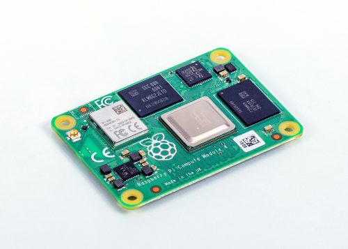
Previous Compute Modules were all in a 200-pin SODIMM form factor, but two important considerations pushed us to think about moving to a different form factor: the need to expose useful interfaces of the BCM2711 that are not present in earlier SoCs, and the desire to add extra components, which meant we needed to route tracks differently to make space on the PCB for the additional parts.
Breaking out BCM2711’s high-speed interfaces
We knew we wanted to get the extra features of the BCM2711 out to the connector so that users could make use of them in their products. High-speed interfaces like PCIe and HDMI are so fast coming out of the BCM2711 that they need special IO pins that can’t also support GPIO: if we were to change the functionality of a GPIO pin to one of the new high-speed signals, this would break backwards compatibility.
We could consider adding some sort of multiplexer to swap between old and new functionality, but this would cost space on the PCB, as well as reducing the integrity of the fast signals. This consideration alone drives the design to a new pinout. We could have tried to use one of the SODIMM connectors with extra pins; while this would give a board with similar dimensions to the existing Compute Modules, it too would break compatibility.
PCB space for additional components
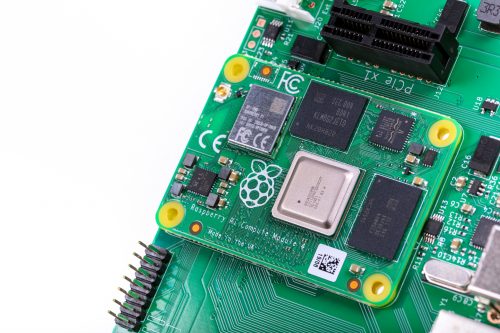
We also wanted to add extra items to the PCB, so PCB space to put the additional parts was an important consideration. If you look carefully at a Compute Module 3 you can see a lot of tracks carrying signals from one side of the SoC to the pins on the edge connector. These tracks take up valuable PCB space, preventing components being fitted there. We could add extra PCB layers to move these tracks from an outer layer to an inner layer, but these extra layers add to the cost of the product.
This was one of the main drivers in changing to having two connectors on different edges of the board: doing so saves having to route tracks all the way across the PCB. So we arrived at a design that incorporated a rough split of which signals were going to end up on each of the connectors. The exact order of the signals wasn’t yet defined.
Trial PCB layouts
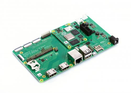
We experimented with trial PCB layouts for the Compute Module 4 and the CM4 IO Board to see how easy it would be to route the signals; even at this stage, the final size of the CM4 hadn’t been fixed. Over time, and after juggling parts around the PCB, I came to a sensible compromise. There were lots of things to consider, including the fact that the taller components had to go on the top side of the PCB.
The pinout was constantly being adjusted to an ordering that was a good compromise for both the CM4 and the IO Board. The IO Board layout was a really important consideration: after we made the first prototype boards, we decided to change the pinout slightly to make PCB layout on the IO Board even easier for the end user.
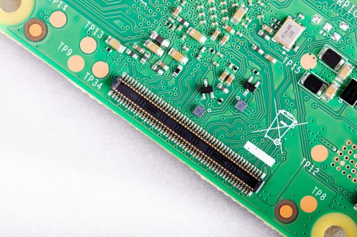
When the prototype Compute Module 4 IO Boards arrived back from manufacture, the connectors hadn’t arrived in time to be assembled by machine, so I fitted them by hand in the lab. Pro tip: if you have to fit connectors by hand, take your time to ensure they are lined up correctly, and use lots of flux to help the solder flow into the joints. Sometimes people use very small soldering iron tips thinking it will help; in fact, one of the goals of soldering is to get heat into the joint, and if the tip is too small it will be difficult to heat the solder joint sufficiently to make a good connection.
New features
Whilst it was easy to add some headline features like a second HDMI port, other useful features don’t grab as much attention. One example is that we have simplified the powering requirements. Previous Compute Modules required multiple PSUs to power a board, and the power-up sequence had to be exactly correct. Compute Module 4 simply requires a single +5V PSU.
In fact, the simplest possible base board for Compute Module 4 just requires a +5V supply and one of the connectors and nothing else. You would need a CM4 variant with eMMC and wireless connectivity; you can boot the module with the eMMC, wireless connectivity gives you networking, and Bluetooth connectivity gives you access to IO devices. If you do add extra IO devices the CM4 also can provide a +3.3V supply to power those devices, avoiding the need for an external power supply.
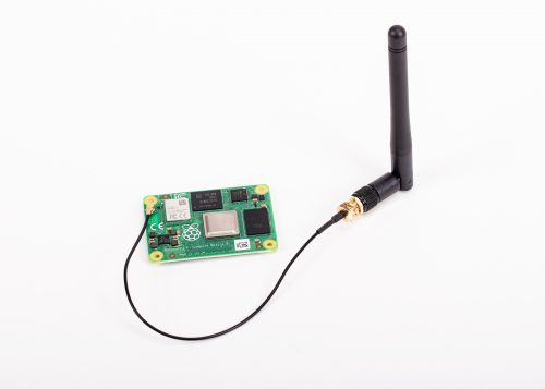
We have seen some customers experience issues with adding wireless interfaces to previous Compute Modules, so a really important requirement was to provide the option of wireless support. We wanted to be as flexible as possible, so we have added support for an external antenna. Because radio certification can be a very hard and expensive process, we have a pre-certified external antenna kit that can be supplied with Compute Module 4. This should greatly simplify product certification for end products, although engineering designers should check to make certain of meeting all local requirements.
PCIe
This is probably the most exciting new interface to come to Compute Module 4. On the existing Raspberry Pi 4, this interface is used internally to add the XHCI controller which provides the USB 3 ports. By providing the PCIe externally, we are giving end users the choice of how they would like to use this interface. Many applications don’t need USB 3 performance, so the end user can make use of it in other ways — for NVMe drives, to take one example.
Ethernet
In order to have wired Ethernet connectivity with previous Compute Modules, you needed to add an external USB-to-Ethernet interface. This adds complexity to the IO board, and one of the aims of the new Compute Module 4 is to make interfacing to it simple. With this in mind, we added a physical Ethernet interface to CM4, and we also took the opportunity to add support for IEEE1588 to this. As a result, adding Gigabit wired networking to CM4 requires only the addition of a magjack; no extra silicon is needed. Because this is a true Gigabit interface, it is also faster than the USB-to-Ethernet interfaces that previous Compute Modules use.
Open-sourcing the Compute Module 4 IO Board design files
Early on in the process, we decided that we were going to open-source the design files for the Compute Module 4 IO Board. We used our big expensive CAD system for Compute Module 4 itself, and while we could have decided to do the design for the IO Board in the big CAD system too and then port it across to KiCAD, it’s easy to introduce issues in the porting process.
So, instead, we used KiCAD for the IO Board from the start, and the design files that come out of KiCAD are the same ones that we use in manufacture. During development I had both CAD systems running at the same time on the computer.
Easier integration and enhanced possibilities
We have made some big changes to our new Compute Module 4 range, and these should make integration much simpler for our customers. Many interfaces now just need a connector and power, and the new form factor should enable people to design more compact and more powerful products. I look forward to seeing what our customers create over the next few years with Compute Module 4.
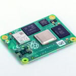
Get your Compute Module 4
The new Raspberry Pi Compute Module 4 is available from our network of Approved Resellers. Head over to the Compute Module 4 product page and select your preferred variant to find your nearest reseller.
Can’t find a reseller near you? No worries. Many of our Approved Resellers ship internationally, so try a few other locations.


52 comments
Grimwood Builds
Excellent! Can’t wait to design an IO board for a new UMPC project. So many possibilities!
Jim Welch
I am confused about dual DSI and dual HDMI. What can be used simultaneously? The same with the CSI, does it interact with the DSI/HDMI ports?
Can I really use 4 displays? or just 2.
Andrew Scheller
LOTS of info in the https://www.raspberrypi.org/documentation although not much of it has been updated for the CM4 yet.
https://www.raspberrypi.org/documentation/hardware/display/README.md
https://www.raspberrypi.org/documentation/configuration/hdmi-config.md
https://www.raspberrypi.org/documentation/configuration/config-txt/video.md
https://www.raspberrypi.org/documentation/hardware/computemodule/cmio-display.md
aBUGSworstnightmare
As I’m doing some driver development atm I’ve made a quick&dirts test with KMS on RPi4 (5.9 kernel): three is possible – https://www.raspberrypi.org/forums/download/file.php?id=40716
But keep in mind that not all combinations of displays will be possible as they use the same SoC blocks
Nigel
Excellent! Thanks for testing and sharing the results.
Harry Hardjono
I wonder how easy it is to flash the eMMC, because I’m used to just plug in the microSD card and be done with it. I’m also spoiled with 128 MB card, instead of 32.
If this is good, the addition of WiFi means that it has a great potential to use as “keychain” computer, with VNC interface to chromebook. I wonder, though, whether or not I can solder the power wire directly to the board, as I cannot find any marking on the board indicating power pads. Any help with these concerns is appreciated. Thanks.
aBUGSworstnightmare
don’t attempt to solder wires to the connectors directly as they are not intended for such kind of miss-use! Design a small carrier board with just one (or both) board-to-board connectors, add your 5V power supply to that board (or just some solder pads for wires) and if 32GB of flash is to less for you add a uSDcard socket and use CM4lite.
Harry Hardjono
Thank you for your response. Such hardware project is unfortunately beyond my ability. Hopefully somebody else will pick it up. A micro SD interface, power line with LED and switch, should do the trick. Pair that with rechargeable battery pack, or just use the power USB from chromebook, and it’s good to go!
I’m currently using RaspiZeroW. Strangely enough, when I transferred the microSD to plain RaspiZero, it stops working! I transferred it back to Raspi ZeroW and it still doesn’t work! I think there’s a hidden change in setting somewhere because it works direct connection in both cases.
Michael Horne
This is a “known, reported” bug. Unfortunately, when you swap SD cards between certain Pis, the wifi gets knocked out :-(
Harry Hardjono
Thank you for letting me know about the bug. I just wish that the changes aren’t hidden. I ended up restarting the whole process from scratch, being careful that I installed dnsmasq before proceeding.
I am now happy that I found a use for the old Raspberry Pi Zero; the original, not the W model. It does make a nice bubblegum computing when paired with my chromebook.
Thanks again.
CooliPi
Can you guys patch the vcgencmd command to report correct negative temperatures, please?
https://www.youtube.com/watch?v=RbzKM5XxlOA
The CM4 will certainly be used in some colder environments than indoors, and some people would wonder why it reports 4 million degrees Celsius…
The code is AFAIK only some printf unsigned format specifier being used instead of signed one when reporting temperatures. I can’t locate the place exactly, downloaded source code from github, no time to fiddle with it. Thanks.
Linux kernel now reports negative temperatures correctly.
AndrewS
vcgencmd “only” passes messages from Linux to the firmware (and prints the firmware’s reply). So if the measure_temp command is still reporting negative values incorrectly, you should report it at https://github.com/raspberrypi/firmware/issues
Mahdi
The bottleneck is the temperature support. Anyone interested in CM family is probably looking to use it in a low volume commercial or industrial project and the new product does not support the correct requirements of industrial environments.
It is still possible to use it in commercial projects but the commercial projects usually have a much higher volume and might worth to design a full system rather than modules.
Suman
By any chance do we have IO bord with industrial graded connectors and industrial-grade case exposing all the connectors and sensors?
Can we use the PCI to connect AI accelerators [ex- coral]?
Jorge
Until today, PCIe do not support the use of Coral EdgeTPU Accelerators like Coral ones.
The problem is that CM4 CPU doesn’t support MSI-X
https://www.raspberrypi.org/forums/viewtopic.php?t=293248
SonoraTechnical
I’m starting to like this product more and more. It’s just a tad large for my existing application with the IOBoard, but I’m considering just fabricating custom mounts to ‘squeeze’ it’s 6.25″ width onto my 6″ backplane and give it the edge the end offset of the 4B so that all of the external interfaces extendout out of the case faceplate. I’ll stack a mini backplane above it to house the components that are displaced by the IOBoard’s size. Perhaps it worth it for the external wifi antenna and eMMC/NVMe options.
Ebrahim
Innovative form factor.
I guess you still have the option to remove the 4 holes (or at least two of them) since it is now fixed by the connectors.
Sgllama
Assuming that the CM4 is held in place by the connectors and therefore the corner mounting holes can be done away with removes the possibility of using the CM4 with just a minimal set of wiring in a flying lead. As noted above, you need run little more than 5V power to make the board useful.
Max
Good job, Dominic! It was the right choice to go to the new form factor, and I’m excited about the many new possibilities the CM4 opens. Indeed, making the power supply sequencing easier is a big win, I believe many more designs should pop up now. Also, of course native PCI Express will allow to do wild things with the new carrier boards – looking forward to introduce some of our own :-)
Matthew
How long do you plan on keeping the new form factor? I’m thinking of a possible rasPi 5 ;) It would be nice to be able to replace only the CM and not need to redesign my PCB.
Geoff
The CM4 looks like a game-changer. Hopefully we will see a healthy market for 3rd party IO boards develop. I, for one, would love to see an IO board that supports NVMe SSDs directly.
pierre-louis boyer
Can the Disp0 or Disp1 display connectors be used with any mipi DSI LCD? Or only with RaspberryPi official ones?
Pierre
Will you also release the PCIe express board CAD? Such as the 4 USB 3.0 board? Such that we can integrate that in our IO board.
modric
How to write a system image into emmc?
Srinivasa Chaithanya
This CM4 Looks good. How long are you planning to keep the new form factor?
Reetesh Haldonkar
Great! CM4 Looks very good. new form factor is cool
Raspberry Pi Modelleri
Great! CM4 Looks very good. new form factor is cool
ABHI
Well, I think that the extra space on the PCB component is really a great idea. I always wanted to customize it but I was short of space.
Ryan
Does anyone know if RPF have any plans to release additional antennae? Like a patch antenna? Their current one is huge and won’t fit our product. If not, is it correct to say that as long as we use an antenna that is the same gain or weaker, it will still be certified?
شركة تنظيف مكيفات بالرياض
THANKS!
Aman pathak
Such informative content. Thank you for sharing with us.
Rajat Bansal
You got a lot done there even after facing so many issues. Backward compatibility and improved PSU are definitely great, keep up the good work!
Sabari
The CM4 is improved on many level with nice features especially added power to external IO devices. Can’t wait it try it out.
Premium Printers
nice blog learned some thing new but still some confusion about io boards
Vikram B
Can the Compute Module run off a single Li-Ion/ Li-Poly battery on the 5V line?
If yes, what peripherals get affected? I’m asking for a headless, small, embedded setup.
Rmalhotra
The CM4 looks like crazy. The new form factor is live!
changok
The layout must be uniform, not changed. I have completed the interface board with the old version and am mass-producing it.
Sreekant Shenoy
Finally, I am happy that they open sourced the IO board. That was much required.
Karl Johnson
Do the Hirose 100 pin connectors specify where pin 1 is? There’s nothing on the datasheet or the 3D model for them. It looks like they can be connected either way around.
Karl Johnson
If we only want to use 100Mb/s ethernet can we just connect 2 pairs of the port? We’re using industrial M12 ethernet connectors and don’t require Gb ethernet.
KEV jagger
Looks nice. Let’s hope pi or some third party comes up with a means of having a touchscreen behind the board to make a rather obvious tablet pi.
Im sure a kit or a modified CM4 with a touchscreen would be a hot seller.
K
Avirup Majumder
The CM4 looks very cool!
Chris McNeil
Unfortunately, it seems that the CM4 isn’t enabling bypassing (some if not all of) the onboard switching power supplies, like Allo did with the CM3 for their audiophiliness USBridge Signature music streamer. Or am I missing something? Integrating all the power supplies for 1 5v input is convenient for some uses but rules out others.
Rohit modak
Recently in my college project i used this Raspberry Pi module to make a autonomous robot. This module is far better than the other ones
kolkata ff
Thank you for your response. Such hardware project is unfortunately beyond my ability. Hopefully somebody else will pick it up. A micro SD interface, power line with LED and switch, should do the trick. Pair that with rechargeable battery pack, or just use the power USB from chromebook, and it’s good to go!
I’m currently using RaspiZeroW. Strangely enough, when I transferred the microSD to plain RaspiZero, it stops working! I transferred it back to Raspi ZeroW and it still doesn’t work! I think there’s a hidden change in setting somewhere because it works direct connection in both cases.,
Rudolf
Good job, Dominic! It was the right choice to go to the new form factor, and I’m excited about the many new possibilities the CM4 opens. Indeed, making the power supply sequencing easier is a big win, I believe many more designs should pop up now.
Brian Haynes
Latterly in my class project i used this Raspberry Pi module to make a autonomous robot. This module is far better than the other ones
Stephen Getter
Trying to design a CM4 IO PCB with a GPS device that needs access to the wifi antenna. Is there a pin on the GPIO hirose connector to which I can route the RF_In pin from my GPS device? Or, do I need to design it with it’s own antenna connector?
Karthik
Very innovative, the form factor as well, and the cm4 seems promising.
Fons
Any circuit or block diagram of CM4 available?
Rupam Nath
I was very worried about the IO board. But after reading this post of yours, all my confusion is gone. Thank you.
MonsterFPS
Will you also release the PCIe express board CAD? Such as the 4 USB 3.0 board? Such that we can integrate that in our IO board.
Comments are closed