Design a Christmas tree-shaped PCB | HackSpace #61
In today’s new issue of HackSpace magazine, Ben Everard shows you how to create some Christmas decorations and learn a new skill. Let’s design our own Christmas tree-shaped PCB.
One of the biggest challenges with learning a new skill is having a project to start with. Too complex a project and it can be hard to know where to start, and you can end up going round in circles and giving up before you’ve really started. Too simple, and it can seem like you’re not really getting anything out of it.

In this article, we’re going to pick our favourite ‘simple but not too simple’ PCB project – Christmas lights. It’ll be a little PCB that holds one or more LEDs that you can solder up. If you want to, you can add a bit more sparkle by adding addressable LEDs, but the point here isn’t to flex your electronics muscles, it’s to get used to PCB software and the process of ordering a PCB from a manufacturer.
There are a few PCB design tools available (Electronic Design Automation, or EDAs). The open-source KiCad is popular with makers and powerful enough for professional use. EAGLE is a commercial tool with a slightly limited free tier for makers. However, we’ve found that the simplest tool for getting started is EasyEDA. It’s web-based, so there’s no need to install anything, and hits the Goldilocks of being simple enough to be easy to understand, yet powerful enough to actually be useful. Most EDAs follow a roughly similar workflow, so if you decide to try others later, your experience with EasyEDA should make that easier.
First, you’ll need to head to EasyEDA.com and log in, (or create a free account if you don’t have one already). Click on EasyEDA Designer, then select ‘STD edition’ in the pop-up. This will take you into the main window.

There are two parts to creating a PCB. First, you have to design the schematic, and then you have to design the PCB to match this schematic. EasyEDA will let you just create a raw PCB without a matching schematic, but it’s hard to make sure you’ve connected everything up properly, so we wouldn’t recommend this method.
Go to File > New > Project and create a new project. This will create a folder in the project’s list on the left-hand side, add a schematic, and drop you into the schematic’s editor.
We’re going to use the ‘commonly used’ components, so you can click the Commonly Library on the left-hand side. This gives us quick access to standard components. All these are available from multiple manufacturers and aren’t tied to a specific thing. For example, you can buy 3 mm LEDs or 0805 LEDs almost anywhere and they’ll fit.
Each component needs a layout on the PCB to accommodate it. This might be pads for surface-mount parts, or holes for through-hole. It might also include PCB cut-outs to make space for the physical shape of the part. This PCB layout is known as the footprint. In EasyEDA, you select the footprint you want when you place a component. For example, we won’t just add an LED, we’ll add a 3 mm LED. Scroll down until you find the LED symbol, and select the footprint LED-TH-3mm_B (the final _B just means that it’s a blue LED and this only impacts the look of the project if in the 3D viewer – you can equally select red or green and it won’t affect our PCB). Feel free to use a different LED footprint if you prefer.

Actually, add two LEDs. We also need two resistors. The resistors are a little confusing. You can select either US (zigzag) or EU (rectangle) schematic symbols, and then any footprint within each option. It doesn’t really matter which symbol you select. The through-hole options are each given a number from 1.2 to 0.3 – this is the size (in inches) between the two holes. Most 0.125-watt resistors will fit into the 0.3-inch footprint, but it can be a bit of a squeeze with some 0.25-watt resistors. Depending on what you have to hand, you’ll probably want one of those two (bear in mind that anything that fits in a 0.3-inch footprint will also fit in a 0.5-inch footprint, but the reverse isn’t true).
Obviously, you can put any value of resistor into the same footprint, but setting the correct value means that it can appear on the PCB and then make the PCB easier to assemble. You can set the value by selecting the resistor and changing the value in the Name box.
The final piece of the puzzle is a way of attaching our power source. We’ll add a header to solder in power leads. How you get the power is up to you. It could be from a bench power supply, or any other source of power approximately 3 to 5 V.
In the connectors section, you’ll see a range of different options with different numbers of pins. HDR stands for header, and that’s the type we want. Not because we’ll actually be adding the headers, but because they give us connections we can solder into. There are socket (F) and pin (M) versions of each, but it doesn’t matter which one we want.
We want two connections – one for power and one for ground. However, it can be good to chain these PCBs together like fairy lights, and this is easier if there are two of each, so the HDR-M-2.54_2x2 footprint is a good choice. 2.54 refers to the pin spacing in millimetres, 2.54 mm being 0.1 inches. No, we don’t know why resistors are sized in inches and headers in millimetres.

Those are all the parts we need, now it’s time to connect them together. There should be a box labelled ‘wiring tools’ that you can use to select how you want to join it all together. We’re going to use the simplest option and use wires. When your mouse is over a component’s connection point, you should see a black circle appear. Make sure that you see that when you start connecting everything up. You can also join wires to wires, and if you do so, you’ll see a red dot to indicate that the wires are all joined.
The only thing we’ve not added so far is the net flag. Again, you can select this from the wiring toolbox and add it in the place shown in Figure 1.
The connections on a PCB are known as nets. Sometimes a net will just join one component to another – as we see with the LEDs and resistors – but sometimes they’re more complex. In our case, there’s a single net that joins the output connections from both resistors to the header pins, and this is what we’ve added the ground flag to. The reason for this will become clear when we design the PCB.
That’s our schematic created. Now you can save the file, and we’ll start making our PCB.
Putting things into place
Go to Design > Convert Schematic to PCB. There’ll be a pop-up asking if you want to check nets. This just basically looks to see that everything is connected to something. This is just a quick sense check – there are many perfectly valid schematics where not all things are connected to things, and there are plenty of ways of messing up a schematic that this won’t pick up. However, it’s a good sense check.
If there are any problems, it won’t generate the PCB and it’ll show you a list with yellow warning triangles on the unconnected nets. Click on them for more info.

Once you’ve sorted this out, you can click on Design > Convert Schematic to PCB again and generate your PCB.
You’ll get a pop-up suggesting making a board outline for the PCB. Usually, this is pretty useful and it’ll take a guess at the right size. However, we’re going to create ours manually a bit later, so click on Cancel.
If it does create a board outline (a rectangle in purple) anyway, highlight it and then press DELETE to remove it.
Next, click on the background and this will let you set the canvas properties. You can set the units to either thousandths of an inch (mil) or millimetres (mm). Pick the one that works for you. You can also set the snap size. When doing larger placements, we often use a snap size of 2.54 mm (100 mil). This lines up with the default grid squares and is the same as the pin spacing on many PCBs. For finer things, you might have to set it smaller.
Now, draw the outline of your PCB. In the Layers and Objects box, make sure the pencil is on the board outline layer, then use the Track tool to draw the shape of your PCB. We’ve opted for little Christmas trees, but you can do whatever shape you want. If you want to get really artistic, you can import images – there is the ability to do this built into EasyEDA, but it doesn’t work very well. The SVG Import Extension is a much better option.
Other than the components that should have been pulled in from the schematic, the other thing we want on the PCB are two 3 mm holes near the header pins. These are to let us use a cable tie to attach the power cables to the board – this makes the power cables much more secure. Use the Hole tool to place two holes, then press ESC to revert to the Selector tool, and then select each hole and adjust the diameter to 3 mm (or whatever size cable tie you have to hand).

Now, place your components wherever you want them. For a simple PCB like this, you can probably put them anywhere, but for more complex PCBs, you might have to think a little about how you can route all the connections.
We’re almost ready to start connecting up our PCB but, before we do, we’re going to convert the entire bottom layer of our PCB to a ground plane. This is a big copper area that’s all connected to ground. We do this for a few reasons – but the main one for PCBs is a little complex. If you have an electrical signal that changes very rapidly, it can emit electrical interference that can affect bits of the PCB that aren’t connected to it. Adding a ground plane helps mitigate this. That’s a very simplistic explanation of a complex phenomenon that we’re not going to delve into further, but ground planes are good and while not really necessary on this PCB, they tidy up the traces and are a good habit to get into.
We’ll add ours to the bottom layer, so select the bottom layer in the Layers and Objects box, then select the Copper Area tool (it looks like two dashed rectangles). Draw around the edge of the PCB. It doesn’t have to be precise, just make sure your entire PCB is inside the copper area. Once it’s done, it’ll calculate the copper area and you should see your PCB fill with blue. If you look very closely, you’ll notice that some of the pads are connected to the blue copper area while some aren’t. You should also note that some of the light blue ‘rats nest’ lines that indicate our connections have disappeared because those connections are now ‘routed’ by the copper fill.

This copper area won’t automatically recalculate if you move components, or do anything that will affect it. If you need to at any point, select the copper area and click ‘rebuild Copper Area’ in the right-hand panel.
The final thing to do is route the rest of our traces. First, make sure that the top layer is selected, then use the Tracks tool to join up all the necessary pads (that are linked by pale blue lines). You’ll probably find that you can do all this in just the top layer, but if you’ve got a bit complex, you might find that you can’t do this. If so, you need to switch to the bottom layer and add some track there. All our components are through-hole, so you can connect to them on either layer.
You can also link top and bottom layers using a ‘via’. These are holes through the PCB that you can connect to from either layer.
Once you’ve fully routed your design, save your work (if you haven’t already), and you can have a look at a 3D render of it by pressing the 3D button.
Ordering your PCB
Now it’s time to order your PCBs. This is the part that many people find daunting, partly because there are lots of options, and partly because it involves parting with real money.
We need to generate a ‘Gerber’ file, this is a standard set of files in a zip archive that is supported by almost every PCB manufacturer out there. There are some slight differences in how Gerbers can be packed, but the output from EasyEDA should work with most fabricators.

Go to Fabrication > Generate Fabrication Files (Gerbers). There’ll be a pop-up asking if you want to check DRC (Design Rules Check). This is a way of checking that your PCBs are actually manufacturable and don’t include things like traces too close to holes. It’s a good idea to check this, but bear in mind that we haven’t taken the time to set the design rules that it’s checking. There are plenty of options and we’re just going with the defaults.
Hopefully, DRC will pass and you’ll be taken on to the ‘download Gerbers’ page. Click on Generate Gerber and you should download a zip file.
There are hundreds of PCB manufacturers to choose from, and they vary quite a lot in price. Most will offer an online quote where you can upload your Gerbers and it’ll tell you straight away what the price will be. Do bear in mind that the shipping can often cost more than the PCBs.
On the PCB order form, there will be a huge range of options and you can usually accept the defaults on all of them. The one exception is that many default to a leaded surface finish, while we’d recommend a lead-free option.
Typically, you’ll have to have at least five copies of your PCB, but see what it says on your manufacturer’s website.
A few options you might see on the PCB order page:
- Material: FR4 – this is the standard type of fibreglass PCBs are made from.
- Thickness: It doesn’t really matter for this – about 1.6 mm is normal.
- Solder mask colour: The majority of your PCB will be covered in this. Green is the most common option, but they all work the same.
- Minimum track spacing: This is unlikely to be a problem with a simple PCB (and DRC will complain if you’ve done anything strange).
- Minimum hole size: This is unlikely to be
a problem.
- Surface finish: Copper corrodes very quickly, so any exposed copper is usually covered with a finish that’s either silver-coloured (HASL) or gold-coloured (ENIG). HASL – which stands for Hot Air Solder Levelling – is far cheaper. We’d strongly recommend going with lead-free HASL.
- Via process: If you’ve not added any vias, this is irrelevant, but if you have, you probably want them tented (i.e. covered in solder mask).
- Copper weight: This is how much copper is on one square foot of PCB. 1 oz is pretty common, and perfect for our use case.
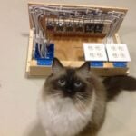
With this selected, you can place your order. Perhaps the hardest part of ordering a PCB is waiting for delivery. This can often take two or three weeks. After this, you can solder them up and see if they work. With the double-header on the top, you can daisy-chain them together to make a Christmas decoration to show off your new-found PCB design skills.
HackSpace magazine issue 61 out NOW!
Each month, HackSpace magazine brings you the best projects, tips, tricks and tutorials from the makersphere. You can get HackSpace from the Raspberry Pi Press online store or your local newsagents.

As always, every issue is free to download in PDF format from the HackSpace magazine website.


No comments
Comments are closed