Alex’s Nixie Clock
Liz: Alex is ten years old. He lives in Texas. He shared his most recent school project with us. It’s a great project and a fantastically clear tutorial: we thought you ought to see it too.
My Mom wanted a Nixie Clock, and I needed to do a project for school. I had a Raspberry Pi I wasn’t using, so I built a Nixie Clock. It took me about 2 months.
My Dad ordered some Nixie tubes and chips from Russia, and bought a 170V power supply to power the Nixie tubes. The first thing to do was to test them:

To start with I installed a tube, chip and power supply onto a breadboard. The chip has 4 input lines (A, B, C, and D) that are used to tell it which number to light up. For example in binary 7 is 0111, so you need to set input A to high, B to high, C to high and D to low (A=1, B=2, C=4 and D=8) to light up the number 7. I tested the first one by using a jumper cable to connect the 4 inputs to either 0V (low) or 5V (high).
Once I knew the first tube and chip worked, I wrote a program on the Rasberry Pi to test them. I used 4 GPIO pins, wired to pins A,B, C and D on the chip. My program would loop through the numbers 0 to 9, and turn on/off the pins by converting to binary using logical AND’s.
For example – for the number 7:
- 7 AND 1 = 1, so pin A would be set high.
- 7 AND 2 = 2, so pin B would be set high.
- 7 AND 4 = 4, so pin C would be set high.
- 7 AND 8 = 0, so pin D would be set low.
Once I had the program working, it was easy to test all the chips and Nixie Tubes. Everything worked, except one tube – the 3 and the 9 would light up at the same time. So I used this for the first digit for the hours, since that only ever needs to show 1.
The Program:
When the Raspberry Pi starts up, it automatically starts my clock program.
I wrote the clock program in C using the geany editor.
When the program starts, first it sets all the digital pins to OUTPUT and LOW to make sure everything is off.
Then I turn on pin 0, which turns on the high voltage power supply using a transistor.
Then I test the clock, which makes the hours show 1 to 12, and minutes 0-59.
Then I start the loop. Once every second I do the following:
- Ask the computer the time (if it is connected to the internet, it will always show the right time).
- The hours come back as a number between 1 and 23, so if the hour is bigger than 12, I subtract 12 from it.
- Then I break out the hour into 2 digits, and the minutes into 2 digits. The first digit is the quotient of the hour divided by 10. The second digit it the remainder of the hour divided by 10. Then I do the same for the minutes.
- For each number, I have to convert it into binary (for example 7 is 0111 in binary). Each number has up to 4 wires, each wire is for a binary digit. If the digit is 0 the pin/wire is set to LOW, if it is a 1 it is set to HIGH. So for the number 7 the wires are LOW, HIGH, HIGH, HIGH.
- These wires are soldered to the driver chip. The chip has 10 switches in it, one for each number in the Nixie Tubes. These switches are connected to the chips with yellow wires. The chips look at the 4 wires to see which binary number it is, and then switches on the correct light in the Nixie Tube.
The table below shows the wires and their values for each digit.
| Digit | Black Wire | Blue Wire | Grey Wire | White Wire | Binary |
| 0 | LOW | LOW | LOW | LOW | 0000 |
| 1 | LOW | LOW | LOW | HIGH | 0001 |
| 2 | LOW | LOW | HIGH | LOW | 0010 |
| 3 | LOW | LOW | HIGH | HIGH | 0011 |
| 4 | LOW | HIGH | LOW | LOW | 0100 |
| 5 | LOW | HIGH | LOW | HIGH | 0101 |
| 6 | LOW | HIGH | HIGH | LOW | 0110 |
| 7 | LOW | HIGH | HIGH | HIGH | 0111 |
| 8 | HIGH | LOW | LOW | LOW | 1000 |
| 9 | HIGH | LOW | LOW | HIGH | 1001 |
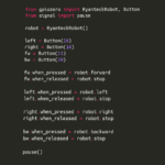
Here is the source code in C:
#include       /* These are libraries */
#include
#include
#include

// turns a pin on or off
void nixiePin(int p, int v){

  if (p != -1) {
    digitalWrite(p, v);
  }
}


// converts to binary and sends values to 4 pins
void nixiePins(int p1, int p2, int p4, int p8, int v){

  nixiePin(p1,v&1);
  nixiePin(p2,v&2);
  nixiePin(p4,v&4);
  nixiePin(p8,v&8);
}


// splits the time into digits
void nixieTime(int h,int m, int s) {

  nixiePins( 1, -1, -1, -1, h/10);  /* quotient of hour / 10  */
  nixiePins( 2,  3,  4,  5, h%10);  /* remainder of hour / 10 */
  nixiePins( 6,  7, 21, -1, m/10);  /* quotient of minute / 10*/
  nixiePins(22, 23, 24, 25, m%10);  /* remainder or min / 10  */
}


// makue sure all the digits work
void testClock(void){
  int i;

  for (i=1; i<=12; i++) {
     nixieTime(i,0,0);
     delay(250);
  }
  for (i=1; i<=59; i++) {
     nixieTime(12,i,i);
     delay(250);
  }
}


// set up the pins we will use
void initPin(int p) {
  pinMode(p, OUTPUT);
  digitalWrite(p, LOW);
}


// this is the main part of the program
int main (void) {
  time_t now;         /* its a variable that holds time info */
  struct tm *ntm;     /* it is a variable */
  int i;

  wiringPiSetup();    /* set up pins 0-7 and 21-29 to use  */
  for (i=0; i <=7;i++) {
    initPin(i);
  }
  for (i=21; i <=29;i++) {
    initPin(i);
  }
  digitalWrite(0, HIGH);            /* turn on high voltage power */
  testClock();                      /* test all the digits */

  while (1) {                       /*starts and infinite loop */
    now=time(NULL);                 /* ask the computer for the time */
    ntm=localtime(&now);            /* it formats the time */
    if (ntm->tm_hour > 12) {        /* if hour is more than 12 - 12 */
      ntm->tm_hour = ntm->tm_hour-12;
    }

    /* it tells it to write that number to the nixie tubes*/
    nixieTime(ntm->tm_hour,ntm->tm_min,ntm->tm_sec);

    delay (1000);   /* wait for 1 second */
  }

  return(0);
}
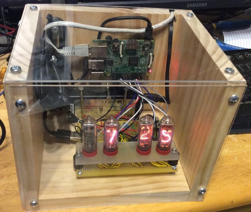
The Circuit Board:

My dad drilled a piece of plastic for me for the Nixie Tubes to sit on.
The circuit board has 4 Nixie tubes, and 4 chips (one for each).
The chips are wired to the Nixie Tubes with yellow wires.
Black wires are used for Ground, and red wires for 5 and 12 Volts. 5V and Ground was wired to each chip.
The Nixie Tubes require 170V DC to work, so in one corner I have soldered a high voltage power supply. This takes 12V and turns it into 170V. All 170V wires are green.
The Nixie Tubes need resistors attached to them, so they don’t take too much current and burn out. The resistors limit the current to 2mA.
There is also a Transistor with 2 more resistors to limit the current. This transistor acts as a switch, and lets my program turn the High Voltage Power Supply on or off.
I also added a USB port, and wired it so it has 5V and Ground. This lets me use it as a power supply for the Raspberry Pi.
Then the inputs to the chips were wired to pins on the Raspberry Pi GPIO (see code for pin numbers).
Soldering took a very long time. Before we turned it on, my Dad checked over everything, making sure the 170V was safe. He found a couple of shorts that had to be fixed.
When I turned it on the first time, the tubes just half glowed and flickered. However if I took two chips out of the sockets, then the other two would work. This was because the 170V power supply wasn’t powerful enough. I double checked the datasheet, I should have been using about 1.5W, well under the 5W the power supply should be able to make from 5V. Instead of running the high voltage power supply on 5V, I tried 12V (it is rated up to 16V input), and that solved the power problem.
The Case:
I made a box out of wood and plastic. I got to use a big circular miter saw with my Dad supervising to cut the wood. The plastic is cut by using a sharp blade to cut into it, and then snapping it. Then everything was screwed together:
What’s Next:
I was very nervous about taking it into school – the last boy that took an electronic clock into school in Texas got arrested, so my Dad contacted the school first to let them know. I think my teacher was impressed, I had to explain everything in detail to her.
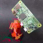
This is only the start of the project. I want to put it in a nicer case with my Dad’s help before I give it to my Mom. I want to add an alarm. I also want to add a hidden camera, microphone and speaker, so it can run voice/face recognition. Then I can turn it into J.A.R.V.I.S. from Ironman. That may take me a while, but I’ll add more posts on my blog as I do things to it.
Liz: Have you made a school project with the Pi that you’d like to share with us? Leave us a note in the comments!


46 comments
Liz Upton
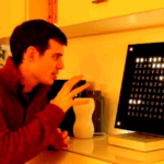
We particularly liked the bit in the video where Alex explains that he took the clock to a school in Texas and did not get arrested.
Jamie
Alex’s comment about being scared to bring his clock to school broke my heart. As if the innocence of youth doesn’t even consider Ahmed’s problem had nothing to do with clocks.
Anyway, this is some decent electronics and coding, I couldn’t have done this when I was 20 never mind 10. Great write up too, very clearly explained, it’s important to have good people skills as well as good technical skills. Really well done Alex!
Martin Bonner
Hmm. I suspect that bit was slightly tongue in cheek. I bet Alex knows exactly why Ahmed had trouble.
Steve D
He was genuinely a little nervous, although he did like the idea of a visit to the white house.
Liz Upton
*Points up* – that’s Alex’s Dad. Hi Steve!
Den
Steve,
You must be a proud daddy. Way to rise up a quality kid.
Michael Ray Overby
‘Decent’ is the wrong adjective IMHO. ‘Tight’ is. This kid’s an American Engineer. Now. Let’s do all that we can to support him & those like him. That’s no Bomb, it’s a Clock he Invented. And Built Proto Hardware for. And Programmed. In Cea, no less. Kids like this deserve Celebration. & Accelerated Training that Befits their genius. This young man has pages in History coming up. American and World History.
Den
Apparently he didn’t look “Middle eastern” enough to warrant being profiled, libeled and arrested. : /
Alex
No he didn’t place it in a suitcase with wire hanging out, that’s why.
Art Bibbs
Any sufficiently advanced technology will be viewed by a much lesser people as MAGIC, except if you are in Texas, it will be viewed as a BOMB (or you may be imprisoned or burned at the stake for witchcraft, or something).
Alex Eames – RasPi.TV
Awesome project Alex. I’ve always fancied doing a Nixie clock as well.
Excellent blog post.
Lorna Lynch
Hurrah for Alex! This is amazing. And to think Eoin was impressed when we put some LEDs on a breadboard…
Alan Mc
Cool project. Well done Alex! Setting the bar high for 10yr old inventors.
@Liz: good to see you back on the blog ;o)
Liz Upton
Thanks Alan! I had to have an emergency operation at the end of October, and I’ve only just come back to work. All better now – it’s very good to be back!
Michael Ray Overby
Any Old Fartz out there got Blue Argon Nixies for this kid? Make the Investment. It’ll be Photogenic. For the Airtime.
Dougie
Liz, you should send a brand new free A+ to Alex to run his Nixie tube clock so he can free up that full size RPi to do his next project.
Rmk
Pretty impressive english for a 10 year old much less the electronics knowledge, no?
Liz Upton
Yes, but it’s not actually that unusual. We meet a LOT of very smart kids doing this.
Steve D
To put it in perspective, he got his first Raspberry Pi for his 8th birthday, so first lit up an LED from Python a couple of years ago. This was his first attempt at C though. It took him about 2 months because of the learning curve, for someone with the experience this would be a weekend project.
edwinj85
10 year olds know better C than I do… Well done to that lad! This is impressive stuff.
Archie Roques
I’m just jealous that he has a mum who not only knows what a Nixie Clock is, but wants him to make one!
Sarah D
Thanks Archie Alex’s Mum here I love Nixie clocks but my electronics knowledge doesn’t go past wiring a plug
HBE
Very well done, and a very nice description indeed. You know that a kid has a talent for science and engineering if he or she will not only tell you how great this is, but also about what didn’t work initially and how long it took to build.
Also nice to see that C won’t go extinct in the next generation :-)
Erbo
Hey, Obama, THIS is a pretty “cool clock”! Where’s THIS kid’s invitation to the White House? (crickets chirping)
Alex
Yes! He didn’t take a circuit board out of an old clock radio and mount it to a suitcase.
Jim Manley
WOW!!! Great job, Alex! By the powers invested in us, by us, for us, we The Raspberry Pi Community do hereby dub thee A.L.E.X. (A Lot of Electronics eXpertise! :) I fooled around with Nixie tubes back when they were brand-new components after seeing them in a Wang calculator at the Franklin Institute long, long ago in a childhood far away …
Never mind allowing an electronic clock into school, I’m amazed they allowed a 170-volt power supply through the doors … although I suppose that probably no one there besides A.L.E.X. knows what 170 volts actually means! I’m really impressed that your program is written in C – we need a _LOT_ more examples like that here and in our other Pi teaching materials. Python is nice, but C puts the iCing on the Cake, CorreCt? Give me a “C”! “C!” What’s that spell? “C!” Nothing like simple and direCt Coding, eh? :D
Steve and Sarah – special kudos to you, also, for inspiring such an amazing young actual engineer (no prospective or future about it – he can even write documentation better than most engineers I know! ;)
Eric Olson
Very nice to see. It appears the source code has been corrupted: the #include lines at the beginning of are missing the usual and so forth. This probably resulted from posting the code on the web without escaping active html characters such as and &. It would be nice to track down where the missing parts of the file went and put things back in order.
Steve D
You are correct – wordpress messed up all the > and < characters, he missed the includes when he fixed them.
It should read:
#include /* These are libraries */
#include
#include
#include
although I don’t thing stdio.h is used – that is there because his starting point was a program he found that got the time and printf’d it.
Steve D
Doh! – did the same in the comments – the includes are stdio.h, time.h, unistd.h and wiringPi.h
AndrewS
Just a suggestion rather than a criticism, but Alex might want to look at http://www.tutorialspoint.com/c_standard_library/c_function_sprintf.htm
As others have already said: this is way beyond what I’d have been capable of when I was 10 years old – well done Alex! The future’s bright…
Milliways
Do they still make nixie tubes? I last used them 45 years ago, but 10 points for style!
Sean Dunlevy
This young man is quite astounding. I would like to see his code!
Liz Upton
It’s right there in the post! :)
Peter Pimley
I think that the realisation that the faulty tube can be used after all is the best part of this story. It’s so easy to get lost in details and forget what it is you’re actually trying to make.
Anonymous Penguin
Great project! I am much more experienced and would never dare to touch anything that needs to be powered with more than 20V, let alone a nixie tube. Congratulations to Alex!
Mark
Great project Alex! Also I thought you wrote a really clear write up. You’ve inspired me to have a go and have taught me some new skills, thanks for the tutorial!
(and well done your mum and dad for supporting you).
Alex
What he did was way more innovative than what Ahmed did. Please stop making him (Ahmed) out to be this great inventor, a 2 year old could do way better. You go Alex, you have done well.
Guido Van Cauwenberge
Hi Alex, I think this is an extremely cool project, did’t even know these tubes are still available. I wish you a lot of success with future projects.
Jasonn
Now this should get him a White House visit, I hate to get political but this is real engineering and work building a clock, very impressive Alex.
Alex
Hi, This looks brilliant, well done.
Do you think it would be possible to put a parts list together of the components you have used … I suppose I’m most interested in getting a bit more detail about the type of “Nixie tubes and chips and 170v power supply” as this looks like a fun and interesting project but these bits of hardware aren’t something that i know about.
Steve D
Thanks (This is his dad, a.k.a. his funding source and chief parts procurer):
Nixie parts all came from eBay.
The tubes are IN-14 Nixie Tubes (new, but dated 1972) per his mothers request – these are mid-sized tubes.
The IC’s are the K155ID1 Nixie drivers (both came from the same seller – I think these IC’s work with any size/style of nixie tube).
There are English translations of the data sheets if you google them – circuit is very simple, just lots of soldering jumper wires to connect the IC’s to the tubes.
The power supply was a ‘Nixie Power Supply 1364’ from eBay also, although I’m guessing he ended up with a fake board – the power supply caused him a lot of problems, he spent several days getting frustrated with it (power output didn’t match the data sheet they reference so he couldn’t run it from 5V as originally planned, the enable pin didn’t work – it was always on, and the pins didn’t line up with the perf board, the only way he could mount it in the end was by using headers soldered at an angle). He did have to use a resistor to set the output voltage to 170V per the data sheet. I suspect there are better choices for the power supply out there, but so far it is working fine.
It was a very educational project for him, both in terms of figuring out how the parts worked (there are plenty of sample circuits and explanations if you google), but also in terms of problem solving approach – more than once he got worried that he wouldn’t be able to complete it. I think sticking with it and pushing through the problems taught him more than anything else…
Prisma Try Laksana
Amazing
Jeff
Wow! This is amazing for a 10 year old! I built a TTL logic driven nixie clock (from scratch) in 1970 as a college project and it ran for 35 years before it fell victim to a fire. There is just something about the glow of neon in a glass tube that makes a nixie clock so unique. Combining the old tube technology with the latest chip building blocks is a great story. Unlike the unfortunate situation with another young student that brought a clock to school, Alex’s project is an actual creation that took some real creativity beyond just taking apart a clock radio and putting it in a briefcase. He has accomplished something at age 10 which is beyond others that are twice his age. It took me until college to do something like this. Well done!!
Jacob Jerrell
This should really get more attention. I never liked being called kid so keep it up Alex. The future is bright and exciting! You may not get a trip to the Whitehouse but just know that you have done something truly remarkable and nothing can hold you back!
Just like learning a second spoken language, you are at the best age to learn programming. Most of my knowledge comes from my youth when I could pick up languages and syntax in little time. Today I spend at least twice as much time trying to learn a new language. Learn everything you can before life gets too busy and let people give you strange looks because your choice reading material is an 800+ page tome about programming. They’ll envy you for it in the future.
Mark Ashmeade
Absolutely outstanding, Alex!
I am 47 years old, you have done something aged 10 that I can only aspire to. I just got my Raspberry Pi yesterday, and I’m recalling all the interfacing circuits I built when I was maybe 5 years older than you and everything was 8 bit. Ask Dad what a 6502 is :)
Your write up of the project was also outstanding. This is what Raspberry Pi is about. WELL DONE!
Melissa
This is incredible! I am really into clocks and this is impressive work. I actually just help write this guide (http://www.bavarianclockworks.com/blog/diy-cuckoo-clock-repair-guide/) and I think it’s safe to say Alex’s tops it!! Thanks for sharing this inspirational post Raspberry Pi.
Comments are closed