More power to your Pi
It’s been just over three weeks since we launched the new Raspberry Pi 3 Model B+. Although the product is branded Raspberry Pi 3B+ and not Raspberry Pi 4, a serious amount of engineering was involved in creating it. The wireless networking, USB/Ethernet hub, on-board power supplies, and BCM2837 chip were all upgraded: together these represent almost all the circuitry on the board! Today, I’d like to tell you about the work that has gone into creating a custom power supply chip for our newest computer.
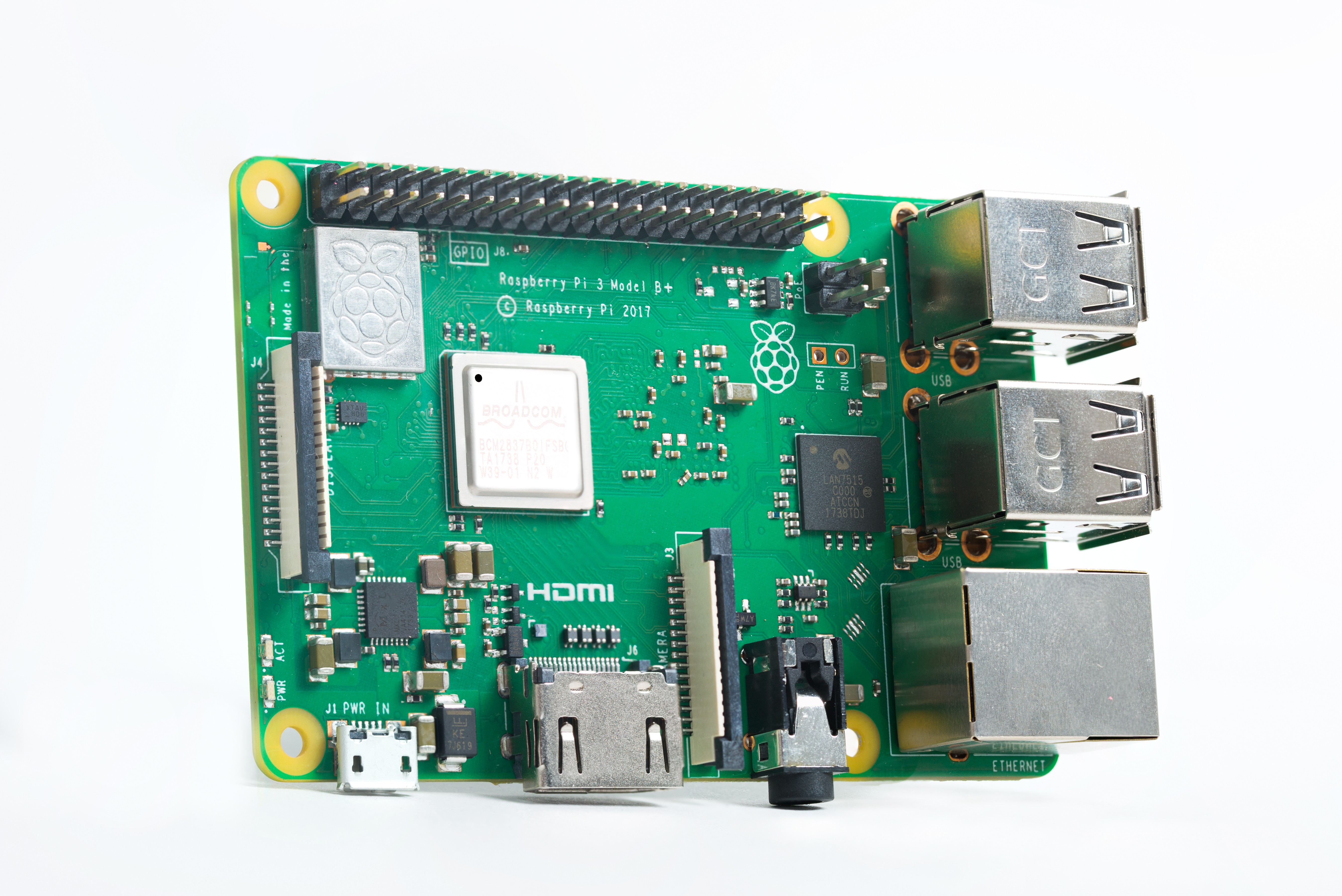
The new Raspberry Pi 3B+, sporting a new, custom power supply chip (bottom left-hand corner)
Successful launch
The Raspberry Pi 3B+ has been well received, and we’ve enjoyed hearing feedback from the community as well as reading the various reviews and articles highlighting the solid improvements in wireless networking, Ethernet, CPU, and thermal performance of the new board. Gareth Halfacree’s post here has some particularly nice graphs showing the increased performance as well as how the Pi 3B+ keeps cool under load due to the new CPU package that incorporates a metal heat spreader. The Raspberry Pi production lines at the Sony UK Technology Centre are running at full speed, and it seems most people who want to get hold of the new board are able to find one in stock.
Powering your Pi
One of the most critical but often under-appreciated elements of any electronic product, particularly one such as Raspberry Pi with lots of complex on-board silicon (processor, networking, high-speed memory), is the power supply. In fact, the Raspberry Pi 3B+ has no fewer than six different voltage rails: two at 3.3V — one special ‘quiet’ one for audio, and one for everything else; 1.8V; 1.2V for the LPDDR2 memory; and 1.2V nominal for the CPU core. Note that the CPU voltage is actually raised and lowered on the fly as the speed of the CPU is increased and decreased depending on how hard the it is working. The sixth rail is 5V, which is the master supply that all the others are created from, and the output voltage for the four downstream USB ports; this is what the mains power adaptor is supplying through the micro USB power connector.
Power supply primer
There are two common classes of power supply circuits: linear regulators and switching regulators. Linear regulators work by creating a lower, regulated voltage from a higher one. In simple terms, they monitor the output voltage against an internally generated reference and continually change their own resistance to keep the output voltage constant. Switching regulators work in a different way: they ‘pump’ energy by first storing the energy coming from the source supply in a reactive component (usually an inductor, sometimes a capacitor) and then releasing it to the regulated output supply. The switches in switching regulators effect this energy transfer by first connecting the inductor (or capacitor) to store the source energy, and then switching the circuit so the energy is released to its destination.
Linear regulators produce smoother, less noisy output voltages, but they can only convert to a lower voltage, and have to dissipate energy to do so. The higher the output current and the voltage difference across them is, the more energy is lost as heat. On the other hand, switching supplies can, depending on their design, convert any voltage to any other voltage and can be much more efficient (efficiencies of 90% and above are not uncommon). However, they are more complex and generate noisier output voltages.
Designers use both types of regulators depending on the needs of the downstream circuit: for low-voltage drops, low current, or low noise, linear regulators are usually the right choice, while switching regulators are used for higher power or when efficiency of conversion is required. One of the simplest switch-mode power supply circuits is the buck converter, used to create a lower voltage from a higher one, and this is what we use on the Pi.
A history lesson
The BCM2835 processor chip (found on the original Raspberry Pi Model B and B+, as well as on the Zero products) has on-chip power supplies: one switch-mode regulator for the core voltage, as well as a linear one for the LPDDR2 memory supply. This meant that in addition to 5V, we only had to provide 3.3V and 1.8V on the board, which was relatively simple to do using cheap, off-the-shelf parts.
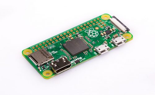
The Pi Zero sports a BCM2835 processor, which only needs two external switchers (the components clustered behind the camera port)
When we moved to the BCM2836 for Raspberry Pi Model 2 (and subsequently to the BCM2837A1 and B0 for Raspberry Pi 3B and 3B+), the core supply and the on-chip LPDDR2 memory supply were not up to the job of supplying the extra processor cores and larger memory, so we removed them. (We also used the recovered chip area to help fit in the new quad-core ARM processors.) The upshot of this was that we had to supply these power rails externally for the Raspberry Pi 2 and models thereafter. Moreover, we also had to provide circuitry to sequence them correctly in order to control exactly when they power up compared to the other supplies on the board.
Power supply design is tricky (but critical)
Raspberry Pi boards take in 5V from the micro USB socket and have to generate the other required supplies from this. When 5V is first connected, each of these other supplies must ‘start up’, meaning go from ‘off’, or 0V, to their correct voltage in some short period of time. The order of the supplies starting up is often important: commonly, there are structures inside a chip that form diodes between supply rails, and bringing supplies up in the wrong order can sometimes ‘turn on’ these diodes, causing them to conduct, with undesirable consequences. Silicon chips come with a data sheet specifying what supplies (voltages and currents) are needed and whether they need to be low-noise, in what order they must power up (and in some cases down), and sometimes even the rate at which the voltages must power up and down.
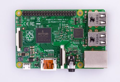
A Pi 2. Power supply components are clustered in the bottom left-hand corner next to the micro USB port, middle (above the LPDDR2 chip, which is on the bottom of the PCB) and above the A/V jack.
In designing the power chain for the Pi 2 and 3, the sequencing was fairly straightforward: power rails power up in order of voltage (5V, 3.3V, 1.8V, 1.2V). However, the supplies were all generated with individual, discrete devices. Therefore, I spent quite a lot of time designing circuitry to control the sequencing — even with some design tricks to reduce component count, quite a few sequencing components are required. More complex systems generally use a Power Management Integrated Circuit (PMIC) with multiple supplies on a single chip, and many different PMIC variants are made by various manufacturers. Since Raspberry Pi 2 days, I was looking for a suitable PMIC to simplify the Pi design, but invariably (and somewhat counter-intuitively) these were always too expensive compared to my discrete solution, usually because they came with more features than needed.
One device to rule them all
It was way back in May 2015 when I first chatted to Peter Coyle of Exar (Exar were bought by MaxLinear in 2017) about power supply products for Raspberry Pi. We didn’t find a product match then, but in June 2016 Peter, along with Tuomas Hollman and Trevor Latham, visited to pitch the possibility of building a custom power management solution for us.
I was initially sceptical that it could be made cheap enough. However, our discussion indicated that if we could tailor the solution to just what we needed, it could be cost-effective. Over the coming weeks and months, we honed a specification we agreed on from the initial sketches we’d made, and Exar thought they could build it for us at the target price.
The chip we designed would contain all the key supplies required for the Pi on one small device in a cheap QFN package, and it would also perform the required sequencing and voltage monitoring. Moreover, the chip would be flexible to allow adjustment of supply voltages from their default values via I2C; the largest supply would be capable of being adjusted quickly to perform the dynamic core voltage changes needed in order to reduce voltage to the processor when it is idling (to save power), and to boost voltage to the processor when running at maximum speed (1.4 GHz). The supplies on the chip would all be generously specified and could deliver significantly more power than those used on the Raspberry Pi 3. All in all, the chip would contain four switch-mode converters and one low-current linear regulator, this last one being low-noise for the audio circuitry.
The MXL7704 chip
The project was a great success: MaxLinear delivered working samples of first silicon at the end of May 2017 (almost exactly a year after we had kicked off the project), and followed through with production quantities in December 2017 in time for the Raspberry Pi 3B+ production ramp.
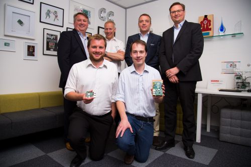
Front row: Roger with the very first Pi 3B+ prototypes and James with a MXL7704 development board hacked to power a Pi 3. Back row left to right: Will Torgerson, Trevor Latham, Peter Coyle, Tuomas Hollman.
The MXL7704 device has been key to reducing Pi board complexity and therefore overall bill of materials cost. Furthermore, by being able to deliver more power when needed, it has also been essential to increasing the speed of the (newly packaged) BCM2837B0 processor on the 3B+ to 1.4GHz. The result is improvements to both the continuous output current to the CPU (from 3A to 4A) and to the transient performance (i.e. the chip has helped to reduce the ‘transient response’, which is the change in supply voltage due to a sudden current spike that occurs when the processor suddenly demands a large current in a few nanoseconds, as modern CPUs tend to do).
With the MXL7704, the power supply circuitry on the 3B+ is now a lot simpler than the Pi 3B design. This new supply also provides the LPDDR2 memory voltage directly from a switching regulator rather than using linear regulators like the Pi 3, thereby improving energy efficiency. This helps to somewhat offset the extra power that the faster Ethernet, wireless networking, and processor consume. A pleasing side effect of using the new chip is the symmetric board layout of the regulators — it’s easy to see the four switch-mode supplies, given away by four similar-looking blobs (three grey and one brownish), which are the inductors.
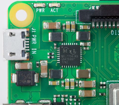
The Pi 3B+ PMIC MXL7704 — pleasingly symmetric
Kudos
It takes a lot of effort to design a new chip from scratch and get it all the way through to production — we are very grateful to the team at MaxLinear for their hard work, dedication, and enthusiasm. We’re also proud to have created something that will not only power Raspberry Pis, but will also be useful for other product designs: it turns out when you have a low-cost and flexible device, it can be used for many things — something we’re fairly familiar with here at Raspberry Pi! For the curious, the product page (including the data sheet) for the MXL7704 chip is here. Particular thanks go to Peter Coyle, Tuomas Hollman, and Trevor Latham, and also to Jon Cronk, who has been our contact in the US and has had to get up early to attend all our conference calls!

The MXL7704 design team celebrating on Pi Day — it takes a lot of people to design a chip!
I hope you liked reading about some of the effort that has gone into creating the new Pi. It’s nice to finally have a chance to tell people about some of the (increasingly complex) technical work that makes building a $35 computer possible — we’re very pleased with the Raspberry Pi 3B+, and we hope you enjoy using it as much as we’ve enjoyed creating it!

46 comments
Richard Sierakowski
Very useful and detailed information. Hopefully the reduced form factor of the PSU supply systems will free up space on the boards especially for the small format boards
Simon Pooley
A very interesting article. Thank you for making the effort to produce and publish it.
AndrewS
Ditto. It’s fantastic to read about all the low-level nitty gritty details :-)
(and also shows the sorts of thing you can achieve when you have the economies of scale of the Raspberry Pi)
lolo
With such articles, the educational purpose of the raspberry pi fundation goes over traditional classrooms.
Thanks for this very instructive content and keep going on.
Len Samuelson
Interesting article, thanks for sharing it. Thanks also to the Raspberry Pi Foundation for building an environment that brings these industrial strength tools to a large population.
Would the new supply solution allow us to use traditional (and traditionally a bit inadequate) USB supplies to power the model 3B+? That would simplify life for those who do not have the option of using the 5.1 / 5.25 Volt supplies we’ve been accustomed to using when we run our RPis in higher performance applications.
Raspberry Pi Staff James Adams — post author
Hi Len I’m afraid you’ll still need a good quality 2.5A power supply for the 3B+ – although this new solution is a bit more efficient the total power requirement has still gone up overall (due to the faster processor, Gigabit Ethernet and dual band wireless).
AndrewS
Does the 3B+ need adding to https://www.raspberrypi.org/help/faqs/#powerReqs ?
Jack Burton
Kudos, for sure ,it does take a lot of people ,and it takes a lot of people/users to make it all worth while ,Thanks for all the hard work to make this great product,, I enjoys your Pi’s more thank my Wife’s pies ,but don’t tell her that. !
shannon
Will this be able to be “back ported” to the Pi2 and Pi3 platforms, since there is not a current plan to end those lines? Maybe reduce productions costs and clean up the power systems on those platforms also? Just curious.
AndrewS
I suppose it depends if the cost-saving of the new PMIC chip outweighs the cost of redesigning the existing Pi2 and Pi3 PCBs?
Raspberry Pi Staff James Adams — post author
Andrew is right, plus the legacy boards are usually bought by customers who have qualified the Pi as part of a system and changing the Pi design in this way would (for some) require expensive re-qualification. It is something we have considered, though.
John Klos
I like articles like these. It helps to have information like this to show people who only ever hear or read about simple feature differences and don’t realize that the whole design is evolving over time. Very nice!
solar
The raspberry pi 3.5?
beta-tester
thank you for the really interesting article.
more interesting to me than all the other articles about the RPi3+ ;)
Fred
Does this mean that the new Pi board can now successfully run a single external 2.5 drive from its USB with no problems?
It’s been a roller coaster ride for me, some power supplies/board/drive combos run fine, others do not.
This is very important for those who configure their Pi’s as a Music or Movie Server.
Thanx Fredly
Raspberry Pi Staff James Adams — post author
The USB 5V (VBUS) output is limited to 1.2A, but this should power a good majority of drives (as long as your upstream power supply is good). I can’t promise that all drives will work.
Artur
How about pushbutton in back of rpi?
Bruce Tulloch
Nice piece James! Good to read about design work that goes in behind the scenes. Unsung stories like this are what makes it all possible. And I could not agree more, power supply design is tricky but critical :)
Raspberry Pi Staff James Adams — post author
Indeed :) thanks Bruce!
Milliways
A very informative article. I have pored over the frustratingly incomplete circuitry of the Pi models to understand their PSU.
PS the picture of the Pi3 is actually a Pi2.
Raspberry Pi Staff James Adams — post author
Well spotted – now fixed, thanks.
Joshua UU
This was a beautifully written article! It was overflowing with useful knowledge but written in a way that I couldn’t stop reading. I can’t imagine this is something that’s easy to do considering you’re writing about power supply chips.
James, if I can find them I would love to read more articles that you’ve written!
Also kudos to the RPI Foundation and everyone involved over the years. I’ve been a PI user since the first batches came out years ago. Not only do I love this product, but even including some growing pains early on this is one of the best run foundations on planet Earth today.
I hope one day I can emulate your strategy and build a non-profit and company I hope is 1/10th as succesfful but more importantly to me, I want to emulate the thoughtfulness, knowledge and good faith you put into your products. You’re changing the world for the better gang!
Sorry for the long read. I just really love what you’re all throwing down!
Raspberry Pi Staff James Adams — post author
Kind words, thanks. Glad you enjoyed reading it!
AndrewS
You can find the other blog articles that James has written by clicking on his face at the top-right of this blog post :-)
masolae
Interesting article, I just wondered where does undervoltage warning messages come from. Now I’m fairly sure that voltage monitoring is a new feature.
Well done
Raspberry Pi Staff James Adams — post author
We’ve had a voltage monitor on the Pi (which monitors the 5V and triggers if it goes lower than 4.6V) since the original B+. The MXL7704 has a similar monitor on-chip which is now read over I2C.
On
The “Power Supply Primer” paragraph is extremely well-written. To bridge the gap between computer science and the real world, we need more text like this… please keep writing!
Craig Van Degrift
Thank you for the very interesting and educational article. The Raspberry Pi Foundation just keeps on providing great products at a price mere mortals can afford!
Andy Suter
So that’s where U4 disappeared to!
Lovely article.
It’s eye-opening, that a charity hoping to sell 10,000 devices over its lifetime can evolve into one with enough clout to have chips specially designed for it.
PIBI
I manage to setup 3B+ in 6. attempt !!
1. dl of files goes ONLY thru Wifi even where 1gb net is present and i succeded in 6.atempt – first 5 died between downloading randomly betweeen 10% in 85%
2.I was thinking about power but i have decent PS (3.5 A)
Card is Kingston 16GB, like on my other 5 RPIs 1-3 and work
normal. Just stops blinking green and % stay at whatever number (not 100 !)
So thats my experience and now I will start with camera and GPS module GP-20U7 or SunfounderSensor kit V2.0
good luck !
Matt Hawkins
This post is another demonstration on why the Pi is so popular compared to some of it’s rivals. There is an attention to detail and a drive to keep making focused incremental improvements. All without blowing away the previous resources, experience and knowledge built up in the community.
Keep up the good work!
Roger
Would the startup sequencing of supplies and current ratings be suitable for a compute module?
If this chip were to be available in small quantities it would appear to be a god-send to designers of cm carrier boards.
KH
Does the new PMIC chip enable power off from software via its I2C interface?
Would be a useful new feature for those of us using Pi’s over SSH, without a keyboard, mouse or display.
Manuel Tijerino
Just want to say thanks for building the RPI and always improving it. I’ve learned so much and have enjoyed using it for years. Kudos to everyone for helping making it better.
beo_6
Hello James,
Nicely done article.
I’m curious about the communication to the mxl7704 too. Is there a way to access the I2C to the chip?
I also made a forum post, as this is going to be a longer discussion. I hope ;-)
https://www.raspberrypi.org/forums/viewtopic.php?f=29&t=210832
JumpZero
Very interesting article. Thanks to keep us informed with engineering details. This is one more reason to love the Pi ;-)
Fischi
On of the things which need a great attention is by my experience the usb cable (of course if you use a power supply without a fixed cable).
In the past I runned i a few of a apparent seeming issues of under voltage which belongs to a wrong usb cable. That’s the rerason that I have a lot of cables at home which I weeded out for not usable on the Rasberry Pi.
In some cases it could be a good idea to give an exchange of the cable a try. I have no finally clue or suggestion but it seems to be that a pure charge cable will be a better expirience than a regular usb cable.
Clint Bradford
Are you still “setting” the price at $35 for the new Pi? I was fortunate to acquire one through Amazon at that price … but the same merchant is now offering them for about US$10 MORE than before. I know you cannot control dealers – but is RaspberryPi.org still ASKING that dealers respect a certain price point?
Trevor Harris
I have a reservation about the power over ethernet board. It has a fan which adds noise and reduces the reliability due to the lifetime of the fan.
IsaacM
Great piece. Highly educational and defeats purpose for a traditional Pi class.Great behind the scenes design work!
Bruce Brooker
Thank you for taking the time and effort in composing and publishing this report. Very informative, very interesting. The Raspberry Pi is the worlds greatest little computer.
LRec
Can you provide maximum case temperatures for the Broadcom CPU package and the WiFi can used on model 3 B+?
Anders Boe
Hi James
Is it possible to remove the xml7704, and power the pi from externals ultra lownoise regulators.
I have removed the power chip on the”old” 3b, and have a remarkable improvement in the sound quality. I use the pi for high end audio, with software from moode audio.
All best
Anders
Sungyul Yoo
I think that this MXL7704 PMIC for RPI3 B+ is different from normal MXL7704(-AQB or -XQB) IC.
these normal part have a default 1.35V voltage level instead of 1.2V for LPDDR4.
(this level can be changed by CPI by I2C protocol.)
But I’m not sure this PMIC is normal part. (or custom part?)
Would you let me know the original PMIC is MXL7704-AQB?
carlcarlcarl
is it okay to supply my rpi 3 with 5v 6ah? thank you
James H Wilson
my new Pi has a tiny fan. Where can I get 5V for it?? (Also I haven’t found a really good Python programing course, they all seem that they are made for people that already know some thing about it. Is there a set of commands for the GPIO??) I realize that this may not the best place to ask these questions but if you can help me or send me to the right place I would deeply appreciate it. I am 71 years old and it takes a while for things to soak in.
Comments are closed