Don’t try this at home: how not to hack the Raspberry Pi display
You may have noticed that the touch display came out a couple of days ago and while the response has been fantastic it’s still a bit early for display-based projects to blog about. But if there’s one thing I’ve learned in three and a half years of blogging for Raspberry Pi it’s this: don’t try and compete with a new product launch. So in the absence of projects using the new display I thought I’d share what not to do with it.
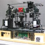
When a new thing comes in to Pi Towers it must prove its worth by a trip to the Maker Grotto (aka my garage, but Maker Grotto feels so much more mysterious and just a little bit Christmassy). Sometimes this is a one-way trip for the new thing. It’s serious stuff. So off we went, all serious like.

The Grotto, specially cleaned for the photo shoot
I had a couple of external 3.5” hard drive cases lying about that looked about the right size for a display enclosure. One—a lovely chunky bit of anodised aluminium by Freecom— was crying out for a window to be cut in the front, but it was getting a bit late to break out the power tools. The other was a cheap third party case and after a few minutes of subtle ultraviolence with the tinsnips the front was off. The display fitted perfectly vertically and pretty well horizontally, with a small overlap at one end. Which didn’t bother me one bit. Not at all. No siree bob.
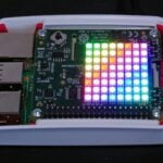
The main problem was that the case wasn’t deep enough if you mounted the Raspberry Pi on the display control board in the obvious way.

Flipping it over made me happy, it was a perfect fit. The header leads that powered the display from the Pi GPIO needed tweaking: remove the plastic ends, heat shrink and bend to 90 degrees. Otherwise very snug and comfy and it brought the overall height down to under 20mm, including sticky-out bits on the back of the Pi. You lose access to the GPIO pins but a ribbon cable would fix that. The DSI connector cable was secure with no stress and a pleasing Mobius strip quality that allows free access to the SD card.

I’ve since been told by Gordon, our Director of Software, that it was designed to do this from the start. But I like to think of myself as a trailblazer of the Inverted Mount. [/me shakes fist like a Beano caretaker]

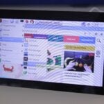
What really, really bugged me was the small overlap at one end. It was taunting me and it needed teaching a lesson. Glass cutter. Straight line. Snap. Sadly the cutter was rather blunt and snap it went indeed—the cut was OK but it introduced edge weaknesses that became a crack under stress. Oops. On the plus side it still works fine and the Pitinerant (and if you think that’s bad the alternative was PeriPitetic) now lives in in my bag—connect it to a portable power bank and a keyboard you have a fully capable Pi.

Forget duct tape, self-amalgamating is where it’s at.
Since then I’ve seen a few enquiries via Twitter as to whether the glass could be “resized”, particularly to make it compatible with the European DIN standard for car audio head units. (We expect to see a lot of car media centres using the display.) The official answer is, “No, you will break it and void your warranty.” And I’ll leave it at that :)
Now there are probably a few people sitting there thinking, “I’ve not even got mine yet and that bugger is smashing his up!” But such is the crazy world of R&D! For what it’s worth I’ve already ordered another out of my own pocket and will buy others—it’s such a great device and it just screams projects. My first scheme is to replace my Pi-based media centre by embedding the display into a bookcase—no more monitor and keyboard cluttering the kitchen.
So the message here is: don’t try this at home. Or, you know, do. And if you make anything cool using the display please share it with us. We’re expecting good things :)

30 comments
Les Pounder
Clive – loving this >> “after a few minutes of subtle ultraviolence” Good work and a really nice screen :)
Jonathan C
“don’t try and compete with a new product launch”
So you’ll be postponing the announcement of the PencilPi for a little while then? :)
alexeames
Great hack. I’m sorely tempted to remove the USB power port, use smaller standoffs and ‘resize the z-axis’ that way – leaving the GPIO pins outward-facing and accessible. (Once a GPIO nut, always a GPIO nut).
bertwert
I think you could probably fit a connector over those GPIO while the pi is upside down.
I would try it, but I can’t afford the Display or a new Pi (I have a dead model B and a working model B as a media centre) right now.
Clive Beale — post author
Idea: pull out the GPIO to a female connector in the top of the case.
Clive Beale — post author
Do it, you know you want to :)
Tzarls
`I’ve seen a few enquiries via Twitter as to whether the glass could be “resized”´
What about drilling a small hole on one of the black borders? That would be great for mounting a front facing Pi camera – imagine a media center that changed playlists according to face recognition results.
Maybe this could be an optional feature on future revs of the display?
Clive Beale — post author
Nice idea, I’ll try this if I can find tile/glass drill.
anotheroldguy
Hmmmmm. Is this a clever ploy to sell more screens? It definitely makes me want to purchase two, so I’ll have one that works after I try at home that which should not be tried at home. 8-)
Nice work, Clive. Very inspirational, with a beautiful final result!
Silviu
Is the touchscreen reliable, for example while painting a line is it a line or a small zig-zag ? Thanks.
killor
Hi !
Where I can get a Mechanical Drawing of the display?
So I could make a wooden enclosure host it.
Thank’s
Dave
Frankly I;m a little surprised they haven’t produced a frame free version for people to tinker with!
Jim Manley
Recall the mandate to bring the screen in at the lowest possible cost. Ironically, that means using a product already in large volume production and not perturbing the existing assembly process which may have many thousands of hours of debugging time built in, as _any_ change can introduce surprising production disruptions. We still don’t have connectorless Pii beyond the Compute Module – it was less expensive and more disruptive to create an entirely new product without any connectors beyond the SODIMM edge pads.
For decades, the U.S. federal government mandated that official government vehicles could not have AM/FM commercial radios installed, and the result was that those vehicles actually cost more than the exact same consumer vehicles with the radios. So, now government employees can actually check the news and be distracted by less serious fare while saving the taxpayers money because some shiny, new, young cost efficiency expert who didn’t know any better pointed out the potential cost savings.
I’ve often wondered whether a business could be made out of the opportunity to perfect the processes needed to remove connectors, bezels, and other such annoyances from Pi products, as well as other mods, at minimal cost.
Clive has kindly helped make that slightly more possible by showing one of the many ways not to do it. Hint, it’s called a glass cutter and not a plastic cutter for a very good reason. Glass is an amorphous inorganic silicate crystal, while plastic is, as its name implies, a pliable material made of long organic molecular chains typically derived from petrochemical components. Plastic molecules are aligned _very_roughly_ parallel to each other in local regions, but not anywhere near that of a crystalline structure and can make twists and turns, especially where injection molded. Glass cutters rely on that precise crystalline structure to propagate the crack that the glass cutting wheel introduces into the surface of a glass sheet. No such crack propagation occcurs, especially in thermoplastics such as that typically used in display bezels.
In a related story, there’s a reason it’s called a “hack” saw :D
Clive Beale — post author
Thanks for the concern Jim, but don’t worry about me and glass — we’re on pretty good terms (I once spent a whole week of a school holiday cutting glass in my uncle’s double-glazing business :)).
The screen bezel is thin, toughened and coated glass; my glass cutter was blunt (couldn’t find my plastic cutter ;)); I may have had a glass of cider… and I messed it up! And then wrote about it :D
Cheers
Clive
Nic
The screen bezel is thin, toughened and coated glass…
Toughened glass is not intended to be cut. The stresses that are induced into the glass in the toughening process (I know it sounds counter intuitive) make for unpredictable cracking if you try to cut it. All shaping is supposed to happen before the toughening process. Hence the waiting period for instance on those fancy frameless shower doors – they are measured and cut to size and then sent away for the toughening treatment.
Clive Beale — post author
I have no idea if it’s toughened really (ie heat tempered) but doubt it due to the way it fractures. I made it up, like I do most things :P
Ulrich
This might be a stupid question but if I just need to take off a centimeter – do you think a file of some sort might work?
Andy
Just one small mistake in the materials lecture at the end Jim – the bezel is actually made of glass.
The “bezel” of the Pi screen is actually just an extension of the screen itself. And the screen is made from amorphous inorganic silicate crystal and not, as you assumed, a pliable material made of long organic molecular chains typically derived from petrochemical components.
Hope that helps!
Wayno
With the addition of a 1mm spacer/washer on each of the standoffs you can flip the pi lengthways with the ribbon between the boards therefore not having to accommodate space taken up by the ‘mobius’ twist in the cable.
Love the fact the screen ‘just works’ too. +1 for the mechanical drawings to help with enclosure design.
Is there a touch enabled GUI option? X isn’t the most finger friendly.
beta-tester
nice idea, to install the RPi upside down…
i don’t like the twisted DSI connector cable…
isn’t it possible to do the same without twisting the DSI connector cable when the USB ports are on the other side (left, instead of on the right) – or is the DSI connector cable not long enough to do that?
Neil
Could it be said that Clive is eating HumblePi?
Michael
Clever, but this could add stress to the ribbon cable if compressed. You might try flipping the Pi over the other way while keeping the ribbon cable in the same position – sandwiching it between the top of the Pi and the adapter board. This will keep the ribbon cable safe and offers a more user friendly solution.
I detailed this over at my blog and even have a basic tablet enclosure .STL file that is freely available for 3D Printing.
http://www.mkcastor.com/2015/09/10/raspberry-pi-7-touchscreen-setup-review-and-case-design/
Enjoy!
-Michael
Liz Upton
*Points up* – that, everybody, is the STUPENDOUS Michael Castor, who made this thing of beauty. He knows what he’s talking about.
Clive Beale — post author
Agreed it’s a better mount for a bespoke (3d printed) enclosure but I was stuck with that orientation for this repurposed (take tinsnips to an old drive case) enclosure. Such is hacking #exaptation ;) The ribbon cable really isn’t under any debilitating stress.
Nice build BTW!
Francis
Hello,
I had the exact same idea of mounting the Pi “up side down” components and connectors facing the screen side to not only gain some heigth but also to have the SD card easily accessible (it is otherwise behind the ribbon cable).
Only one thing needs to be changed: deliver the metallic spacers as 4 to 5mm longer … then no stress anywhere, no bend of the delivered jumper cables, no risk of short circuits anywhere … Done !
More compact, easier to access SD card …
In the absence of longer spacers, you may manage to just add the 2 or 3 extra milimeters by using either an extra short spacer of by adding some washers above the interface board and below the Pi PCB …. beware not to create any shortcircuit !
Francis
In fact I did exactly what Wayno described above …. neat and clean ..
Sorry for the duplication.
Louis-Philippe Breton
Here’s a trick which might seems obvious to some but wasn’t for me. If you power your Pi via USB cable, you doesn’t need to bend the two GPIO leads to invert the mounting! It fits without any modifications.
By Any Means
I found a few old LCDs around the house today but it looks like I am going to have to learn how to sauder :(
t..r.p
Hi,
Here’s my production : an ebook reader inside a cigar box https://vimeo.com/142501686%5D. I’m ready for http://databit.me !
Thomas
Flip it the other way and you won’t have problems with the moebious formation. It will wave effortlessly in under the board. this also allows for better GPIO access as the GPIO pins will sit over more or less blank space instead of the usb connector :)
Comments are closed