Compute Module 5 Programming Jig
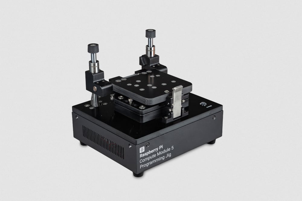
The Compute Module 5 Programming Jig is a provisioning system that programs one Compute Module 5 (CM5) at a time with an operating system (OS) and security configuration. The jig connects directly with each CM5, eliminating the need for a separate IO board during provisioning.
The jig runs Secure Boot Provisioner (rpi-sb-provisioner) to automate the provisioning workflow. When you insert and secure a CM5 into the jig, the jig automatically performs all configuration steps, including secure boot implementation, full-disk encryption, and operating system installation.
Specifications
Edit this on GitHub
This section describes the physical characteristics and capabilities of the Compute Module 5 Programming Jig, including specifications, features, and hardware.
| Specification | Description |
|---|---|
Compatible devices |
Raspberry Pi Compute Module 5 (CM5) |
Provisioning capacity |
Single-device provisioning; the jig configures one CM5 at a time |
Jig network interface (JIG ETH) |
Ethernet (10/100/1000) or Wi-Fi (2.4 GHz and 5.0 GHz IEEE 802.11 b/g/n/ac). |
CM5 network interface (DUT ETH) |
Ethernet (10/100/1000) |
Dimensions (including antenna) |
170 × 181.5 × 153 mm |
Weight |
1800 g |
Features
-
Mechanical clamping. The jig secures the CM5 in place during programming.
-
Carrier board-free provisioning. The jig uses spring-loaded pogo pins to interface directly with a CM5, eliminating the need for a carrier (IO) board and reducing wear on the high-density pin connectors.
-
LED status indicators. The jig displays its current state and provisioning progress through dedicated LEDs. For more information about these LEDs, see LED behaviour
-
Dual network connectivity. The jig connects to the provisioning network by Ethernet (JIG ETH) or Wi-Fi®, with a second Ethernet port (DUT ETH) providing accelerated software transfer to the CM5 being programmed.
-
Automated provisioning. The jig automates the provisioning workflow, including OS installation, full-disk encryption, and secure boot configuration (depending on the level of security you choose).
-
Three levels of security. You have the option to configure the jig to program a CM5 with one of three levels of security: full security (
secure-boot), encrypted storage and device-unique keys (fde-only), and OS-only (naked). For more information, see Levels of security. -
User serviceable. The jig comes with tweezers and replacement pogo pins to enable you to remove and replace any pogo pins that become damaged. For more information, see Replace pogo pins.
|
Warning
|
Don’t touch the pogo pins because they’re sharp and can carry charge; you might damage the pins, the jig, or yourself. |
Hardware
The Compute Module 5 Programming Jig box contains the following parts:
-
A Compute Module 5 Programming Jig.
-
A global power supply with 110 V to 240 V AC input and 12 V at 2 A (24 W) DC output.
-
A Wi-Fi antenna.
-
Two RJ45 cables.
-
Five spare pogo pins.
-
A pair of tweezers.
During usage, you interact with the Compute Module 5 Programming Jig connectors and module bay. There’s also a safety button that you don’t interact with directly.
Connectors
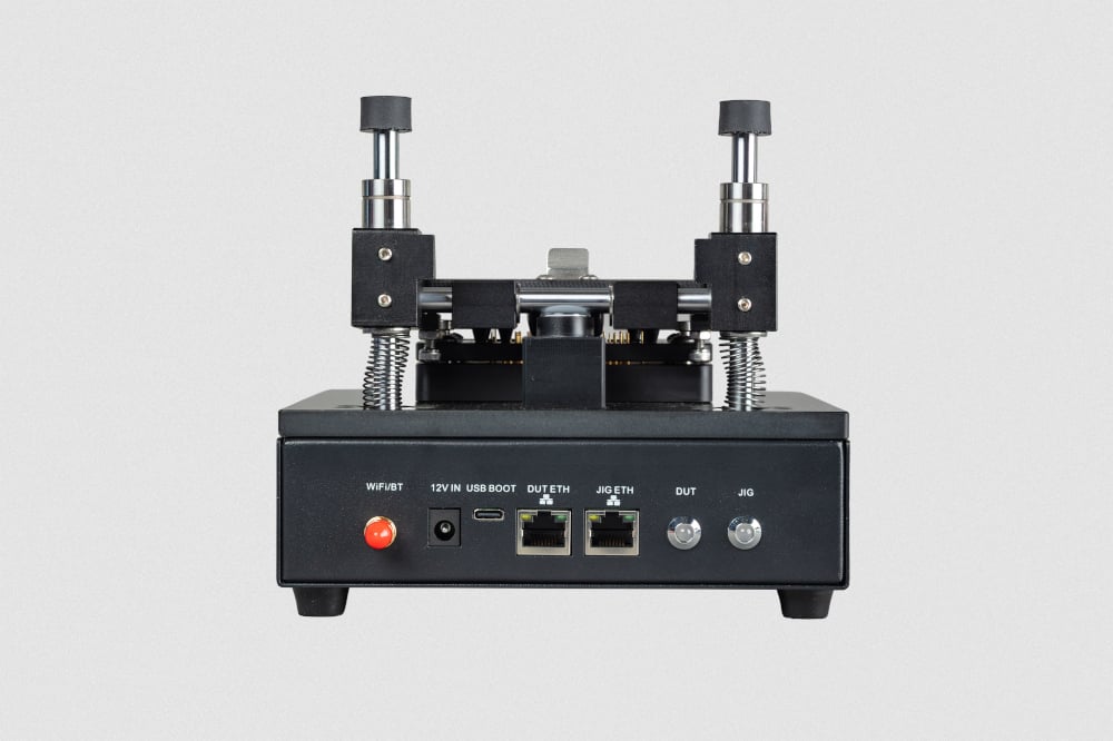
The back of the Compute Module 5 Programming Jig provides the following external connectors:
| Label | Description |
|---|---|
WiFI/BT |
The attachment point for the included antenna. |
12 V IN |
A barrel power jack that accepts 12 V at 2 A (24 W) DC input from the supplied power supply. |
USB BOOT |
A USB-C port used to connect your jig to a computer when using Raspberry Pi Imager to write the jig’s operating system (see Step 2: Write the operating system to the jig). |
JIG ETH |
An RJ45 Ethernet port for connecting the jig to the provisioning network for configuration, management, and software updates. |
DUT ETH |
An RJ45 Ethernet port for connecting an inserted CM5 to the provisioning network for accelerated data transfer during provisioning. |
As an alternative to the JIG ETH port, you can connect the jig to the provisioning network wirelessly using Wi-Fi.
Module bay
The module bay on top of the Compute Module 5 Programming Jig holds the CM5 that’s being programmed.
The CM5 fits snugly within the module bay with the Raspberry Pi logo on the CM5 facing up and in the same orientation as the Raspberry Pi logo on the jig. The metal latch at the front of the module bay holds it closed.
Set up the jig
To set up the jig for the first time, you need the following:
-
A Raspberry Pi Compute Module 5 Programming Jig.
-
The supplied 12 V, 2 A (24 W) power supply.
-
A USB-C cable.
-
A computer with Raspberry Pi Imager version 2.0.11 or later installed on it.
-
Access to the Raspberry Pi Compute Module 5 Programming Jig manifest.
-
Access to the provisioning network (Ethernet or Wi-Fi).
Step 1: Configure Raspberry Pi Imager
You must first configure Raspberry Pi Imager to use the Compute Module 5 Programming Jig manifest and enable RPIBOOT support.
Configure the manifest
You can configure the Compute Module 5 Programming Jig manifest automatically or manually.
-
Automatic configuration
-
Manual configuration
To open Raspberry Pi Imager with the custom repository configured, enter the following URL into your web browser: rpi-imager://open?repo=https://downloads.raspberrypi.com/cm5-jig/cm5-jig.rpi-imager-manifest.
To configure the repository manually, open Raspberry Pi Imager and complete the following steps:
-
Select App Options from the bottom left.
-
Next to Content Repository, select Edit. The Content Repository window opens.
-
Select Use custom URL.
-
In the displayed field, enter the manifest URL (
https://downloads.raspberrypi.com/cm5-jig/cm5-jig.rpi-imager-manifest). -
Select Apply & Restart.
Enable RPIBOOT support
To configure Raspberry Pi Imager to support RPIBOOT, complete the following steps:
-
Open Debug Options:
-
On Windows or Linux, type Ctrl + Alt + S.
-
On macOS, type Cmd + Option + S.
-
-
Scroll to Advanced Features.
-
Use the toggle to select Enable Rpiboot/Fastboot Support.
-
Select Apply to save your changes and exit the Debug Options dialog.
If you’re using Raspberry Pi Imager to set up multiple jigs, you need to enable RPIBOOT support only once; Imager saves this settings for subsequent writes.
Step 2: Write the operating system to the jig
With Imager configured to use the custom content repository, you can now write the OS to the jig.
-
Connect the USB-C cable from your computer to the jig’s USB BOOT port.
-
Connect power to the jig.
The jig boots into USB mass-storage mode. Your computer detects the jig’s internal storage as a removable drive.
-
Open Raspberry Pi Imager on your computer.
-
On the Device tab, select Raspberry Pi Compute Module 5 Programming Jig. Select Next.
-
On the OS tab, select Compute Module 5 Programming Jig as the operating system image. Select Next.
-
On the Storage tab, select the jig’s internal storage as the target. This is listed as Raspberry Pi Compute Module 5 Lite. Select Next.
-
On the Customisation tabs that follow, configure the operating system:
-
Set a hostname for the jig.
-
Select your capital city to set the localisation settings.
-
When creating a username, you must specify the username jig. You can set a password of your choice for this account.
-
Optional: If you plan to connect the jig by Wi-Fi, configure your wireless network credentials.
-
Optional: Enable SSH for remote access.
-
Associate the jig with your Raspberry Pi Connect account for remote management.
-
-
On the Writing tab, check your settings and, if these are correct, select Write.
-
After Raspberry Pi Imager has finished writing, disconnect the USB-C cable and power cycle the jig by removing and reinserting the power cable.
Step 3: Connect to the provisioning network
Connect the jig to your provisioning network using one of the following methods:
The jig uses the connection to the provisioning network to:
-
Provide Raspberry Pi Connect screen sharing and SSH access.
-
Download software updates.
-
Transfer OS images to the jig.
|
Warning
|
The provisioning network always has direct access to the jig. If you also connect the DUT ETH port to the provisioning network (see Step 4: Connect the DUT ETH port (optional)), the network has direct access to devices during programming. Consider the design of this network as part of your threat model. Ensure that only authorised systems and personnel have access to the provisioning network. |
Connect using Ethernet (recommended)
To connect the jig to your provisioning network over Ethernet:
-
Ensure the jig is powered off by unplugging the power cable.
-
Connect an Ethernet cable from your provisioning network to the jig’s JIG ETH port.
-
Power on the jig by plugging in the power cable.
The jig obtains a network address automatically using DHCP.
Connect using Wi-Fi
If you configured Wi-Fi credentials in Raspberry Pi Imager, the jig connects to your wireless network automatically on boot.
-
Ensure the jig is powered off by unplugging the power cable.
-
Ensure the Wi-Fi antenna is attached to your the back of your jig.
-
If your jig has an Ethernet cable connected to the JIG ETH port, disconnect this cable from the jig.
-
Power on the jig by plugging in the power cable.
The jig connects to the configured wireless network.
Step 4: Connect the DUT ETH port (optional)
For accelerated data transfer during provisioning, connect an Ethernet cable from the provisioning network to the jig’s DUT ETH port. This provides a direct Ethernet interface to the CM5 being programmed.
Step 5: Access the Secure Boot Provisioner web interface
The Secure Boot Provisioner (rpi-sb-provisioner) web interface is only available on localhost. This is a security measure that enforces authentication against the jig. To access the web interface, use Raspberry Pi Connect screen sharing to access the jig’s desktop remotely.
-
Sign in to Raspberry Pi Connect.
-
Select your jig from the device list.
-
Start a screen sharing session by selecting the Connect button and choosing Screen Sharing.
If the Secure Boot Provisioner web interface isn’t already open on the jig’s desktop, open Chromium on the jig’s desktop and go to http://localhost:3142.
Step 6: Transfer the client OS image to the jig
Before you can configure provisioning, you must transfer the OS image that you want to install on your CM5 devices to the jig.
The image must be an uncompressed .img file created with rpi-image-gen.
We recommend using Magic-Wormhole to transfer the image from your computer to the jig. magic-wormhole provides a secure, one-time file transfer between two computers. To use this method, both computers must have access to the internet.
-
On your computer, install
magic-wormhole. For more information, see Magic-Wormhole. -
On your computer, use the following command to send the image file:
wormhole send <path-to-image-file>magic-wormholedisplays a receive code. Note this code for use on the jig. -
Connect to the jig over SSH, or use a terminal in the Raspberry Pi Connect screen sharing session.
-
On the jig, use the following command to install
magic-wormhole:sudo apt install -y magic-wormhole -
On the jig, use the following command to receive the image file, replacing
<code>with the receive code you obtained when you sent the image file from your computer:wormhole receive <code>
Step 7: Configure the Secure Boot Provisioner
-
Open the Secure Boot Provisioner web interface as described in Step 5: Access the Secure Boot Provisioner web interface.
-
On the Options tab, configure the following options:
-
In the OS Image section, select Upload New Image and select or browse to the operating system image that you transferred to the jig.
-
In the Device & Firmware section, for Device family, choose Raspberry Pi 5.
-
In the Device & Firmware section, for Storage Type, choose eMMC.
-
In the Security Configuration section, for Provisioning Style choose the level of security. For more information, see Levels of security
-
Signing key: For
secure-bootmode, provide a signing key. The web interface guides you through creating one.
-
For more information about configuration options, see the Secure Boot Provisioner configuration reference.
Program a Compute Module 5
Use the Compute Module 5 Programming Jig to provision a Compute Module 5 (CM5) with an operating system image.
Before you begin, ensure that the jig is:
-
Powered on, with the JIG and STATUS LEDs showing green.
-
Connected to the provisioning network. For more information, see Step 3: Connect to the provisioning network in the Set up the jig instructions.
-
Configured with an operating system image and provisioning options. For more information, see Step 7: Configure the Secure Boot Provisioner in the Set up the jig instructions.
Step 1: Insert the CM5 into the jig
-
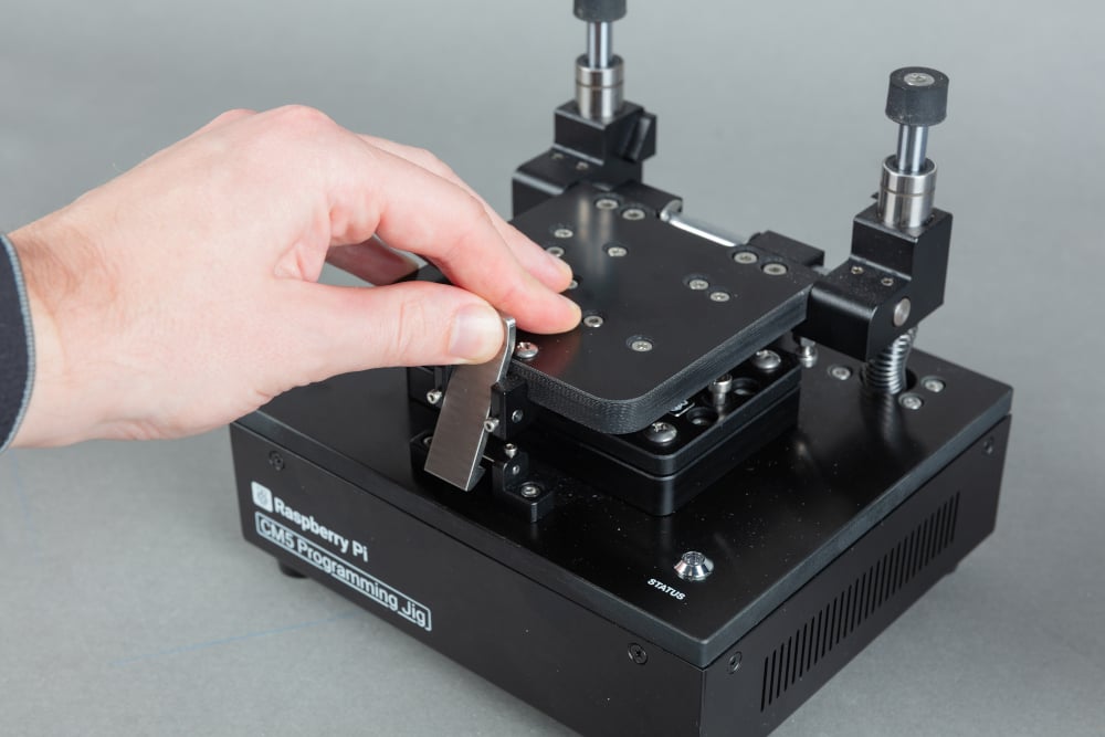
Press the top of the latch backwards to release the clamping mechanism, allow the lid to slide up, and then pivot the lid back until it stops.
-
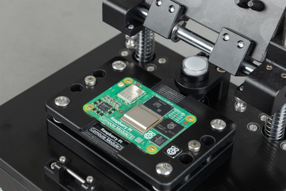
Place the Compute Module 5 into the module bay with the Raspberry Pi logo on the CM5 facing up and in the same orientation as the Raspberry Pi logo on the jig. Align the holes on the corners of the Compute Module 5 with the through-hole studs on the corners of the module recess. The studs thread through the holes on the CM5.
-
Close the clamping mechanism by pivoting the lid forwards until it is parallel with the CM5 and pressing the lid so it slides down. When it reaches the bottom, the latch engages and secures the CM5 in place.
|
Warning
|
Ensure that the through-hole studs pass through all four corner holes on the CM5 before closing the lid. Incorrect alignment can result in a failed provisioning attempt or damage to the pogo pins. |
Step 2: Monitor provisioning progress
After the CM5 is clamped in place, the jig begins provisioning automatically. If provisioning doesn’t start automatically, see Device not detected.
Typical provisioning time is approximately 1.5 minutes for each CM5 with a 2.6 GB OS image installed using the naked provisioning style. Actual time varies depending on OS image size, storage type, level of security, and network speed.
|
Warning
|
Don’t remove the CM5 from the jig while provisioning is in progress. Don’t press the unmarked button on the jig. Either of these actions can render the CM5 unusable. |
Monitor the STATUS LED on the jig to track progress through the provisioning phases:
| Status LED | Phase | Description |
|---|---|---|
Flashing blue |
Provisioning |
The jig detects the CM5 and loads a temporary Linux environment. In The jig selects the appropriate provisioning service based on the level of security you chose in Step 7: Configure the Secure Boot Provisioner. The jig creates encryption keys (if applicable), formats storage, and installs the operating system. |
Green |
Success |
Provisioning is complete. The CM5 can be removed. |
Flashing red |
Provisioning failed |
The provisioning process failed. For more information, see Troubleshooting. |
For more detailed progress information, you can also use the Secure Boot Provisioner web interface. Access http://localhost:3142 as described in Step 5: Access the Secure Boot Provisioner web interface, then:
-
Select the Devices tab to see provisioning progress.
-
Select a device to view detailed logs about it.
Step 3: Remove the CM5
When the STATUS LED turns green, provisioning is complete. You can remove the CM5.
-
Open the clamping mechanism. Press the top of the latch backwards to release it, allow the lid to slide up, and then pivot the lid back until it stops.
-
Remove the CM5 from the module bay.
The CM5 is now ready for deployment.
View the manufacturing database
If you enabled the manufacturing database in the Secure Boot Provisioner, the jig records details about each provisioned CM5 in this database, including:
-
Serial number
-
Board type and revision
-
MAC address (Ethernet)
-
Provisioning date and time
-
Installed OS image
-
Security settings
You can view the information in the database through the Secure Boot Provisioner web interface or by using the command line.
Connect to the jig through Raspberry Pi Connect and export the database as a CSV file:
-
Using the web interface
-
Using the command line
To export the manufacturing database to a CSV file from the web interface:
-
Access http://localhost:3142 on the jig as described in Step 5: Access the Secure Boot Provisioner web interface.
-
Go to the Manufacturing Database tab.
-
Select Export as CSV to download a spreadsheet file.
Export the manufacturing database to a CSV file by running the following command:
sqlite3 ${RPI_SB_PROVISIONER_MANUFACTURING_DB} \
  -cmd ".headers on" \
  -cmd ".mode csv" \
  -cmd ".output devices.csv" \
  "SELECT * FROM rpi_sb_provisioner;"
Update the jig
To get the latest security features, we recommend that you keep your jig software up to date.
To update the jig’s operating system and all installed software, including Secure Boot Provisioner, connect to the jig over SSH or use a terminal in the Raspberry Pi Connect screen sharing session and then run:
sudo apt update && sudo apt full-upgrade -yReplace pogo pins
The Compute Module 5 Programming Jig is constructed to enable you to replace any pogo pins that become damaged.
To complete this procedure, you need the following items:
-
Replacement pogo pins
-
Tweezers
-
3 mm Allen key
During this procedure, avoid touching the pogo pins with your bare hands; doing so might transfer grease and dirt to them.
To replace one or more pogo pins, complete the following steps:
-
Ensure the jig is disconnected from the power.
-
Press the top of the latch backwards to release the clamping mechanism, allow the lid to slide up, and then pivot the lid back until it stops.
-
Use the Allen key to unfasten the bolts in the middle of each of the two short edges of the module bay. Retain these bolts to use for reassembly.
-
Lift the module bay straight upwards and away from the pogo pins in the jig. The four guideposts at the corners ensure that you can do this without fouling the pogo pins. Retain the module bay to use for reassembly.
-
Use the tweezers to grip a pogo pin that you want to replace and pull it straight upwards and out of the collar.
-
Use the tweezers to insert the replacement pogo pin into the collar. Ensure that the larger diameter end with a hole in it goes into the collar first and that the smaller diameter end points upwards.
-
Use the flat of the tweezers to gently press down on the pogo pin and ensure it’s flush with the collar when compressed.
-
After you have replaced all the pogo pins that you want to, replace the module bay.
-
Position it with the Raspberry Pi logo and text facing upwards and with the text on the edge closest to the front of the jig.
-
Line up the guideposts in the four corners of the module bay with the corresponding holes in the jig.
-
Slide the module bay down and into position. The guideposts ensure that this operation doesn’t foul the pogo pins.
-
-
Secure the module bay by reinserting the two bolts you removed earlier and tightening them with the Allen key. Don’t over-tighten these bolts.
LED behaviour
The jig uses LED indicators to communicate its current state. The following table describes each LED and its meaning.
There are two LED indicators on the back of the jig, JIG and DUT, and one LED on the top, STATUS.
| LED | State | Meaning |
|---|---|---|
JIG |
Off |
The jig isn’t powered. Plug in the power cable to bring the jig online. |
JIG |
Solid green |
The jig is powered on. |
JIG |
Flashing green |
The jig is active; data transfer is in progress. |
JIG |
Solid red |
The jig powered on but the CPU isn’t running. |
DUT |
Off |
The jig isn’t powered or no CM5 is inserted. |
DUT |
Solid green |
The CM5 is detected and powered. |
DUT |
Flashing green |
The CM5 is active; data transfer is in progress. |
DUT |
Solid red |
This can indicate that the CM5 is damaged. If this light remains red with multiple different modules, it might indicate a problem with the jig. For more information, see Troubleshooting. |
STATUS |
Off |
The jig is powered off. Plug in the power cable to bring the jig online. |
STATUS |
Solid red |
The jig is powered, but not yet ready to provision a CM5. |
STATUS |
Flashing blue |
Provisioning in progress. Don’t remove the CM5 during this phase. |
STATUS |
Solid green |
If there isn’t a CM5 in the jig, the jig is ready to begin provisioning. If there is a CM5 in the jig, provisioning completed successfully and the CM5 can be removed. |
STATUS |
Flashing red |
Provisioning failed. |
Troubleshooting
If you experience issues with the Compute Module 5 Programming Jig, use the following information to diagnose the issue.
-
If provisioning doesn’t start when the CM5 is clamped in the jig, attempt the steps in Device not detected to resolve the issue.
-
For other issues, see the Secure Boot Provisioner troubleshooting information.
Device not detected
If the CM5 is clamped in the jig, but provisioning doesn’t start, try the following:
-
Ensure that the jig is powered on and connected to the network.
-
If the JIG LED indicator isn’t lit, ensure that the power cable is plugged in.
-
Verify the network by connecting to the jig from another computer.
-
-
Ensure that the CM5 is correctly seated and aligned with the pogo pins.
-
Open the clamp.
-
Reposition the CM5, ensuring that the Raspberry Pi logo is facing up and in the same orientation as the logo on the jig, and that the through-hole studs on the jig pass through all four corner holes on the CM5.
-
Ensure that the Compute Module is well-seated into the module bay recess and has no play in any horizontal direction.
-
Close the clamp again.
-
-
Check whether the pogo pins are dirty or damaged.
-
Inspect the pogo pins for debris or damage.
-
If the pogo pins are dirty, gently clean them with a cotton swab dipped in isopropyl alcohol or a specialist cleaning fluid.
-
Safety warnings
-
Disconnect the jig from the power supply before performing any maintenance.
-
Don’t touch the metallic pogo pins in the module bay. They are sharp and can carry charge; you might damage the pins, the jig, or yourself.
-
Ensure that the CM5 is correctly seated in the module bay as described in Step 1: Insert the CM5 into the jig. Seating it incorrectly can damage the pogo pins.
-
Don’t remove the CM5 from the jig while the provisioning process is in progress (STATUS LED is flashing blue); this can render the CM5 unusable.
-
Don’t press the unmarked button on the jig; this can interrupt provisioning and render the CM5 unusable.
-
Don’t insert a Compute Module 4 into the Compute Module 5 Programming Jig.