import array, time
from machine import Pin
import rp2

# Configure the number of WS2812 LEDs.
NUM_LEDS = 31
PIN_NUM = 28
brightness = 1

@rp2.asm_pio(sideset_init=rp2.PIO.OUT_LOW, out_shiftdir=rp2.PIO.SHIFT_LEFT, autopull=True, pull_thresh=24)
def ws2812():
    T1 = 2
    T2 = 5
    T3 = 3
    wrap_target()
    label("bitloop")
    out(x, 1)               .side(0)
[T3 - 1]
    jmp(not_x, "do_zero")   .side(1)
[T1 - 1]
    jmp("bitloop")          .side(1)
[T2 - 1]
    label("do_zero")
    nop()                   .side(0)
[T2 - 1]
    wrap()# Create the StateMachine with the ws2812 program, outputting on pin
sm = rp2.StateMachine(0, ws2812, freq=8_000_000, sideset_base=Pin(PIN_NUM))

# Start the StateMachine, it will wait for data on its FIFO.
sm.active(1)

# Display a pattern on the LEDs via an array of LED RGB values.
ar = array.array("I",
[0 for _ in range(NUM_LEDS)])

##########################################################################
def pixels_show():
    dimmer_ar = array.array("I",
[0 for _ in range(NUM_LEDS)])
    for i,c in enumerate(ar):
        r = int(((c >> 8)
& 0xFF) * brightness)
        g = int(((c >> 16)
& 0xFF) * brightness)
        b = int((c
& 0xFF) * brightness)
        dimmer_ar
[i] = (g<<16) + (r<<8) + b
    sm.put(dimmer_ar, 8)
    time.sleep_ms(10)

def pixels_set(i, color):
    ar
[i] = (color
[1]<<16) + (color
[0]<<8) + color
[2]

def pixels_fill(color):
    for i in range(len(ar)):
        pixels_set(i, color)

def color_chase(color, wait):
    for i in range(NUM_LEDS):
        pixels_set(i, color)
        time.sleep(wait)
        pixels_show()
    time.sleep(0.2)

def wheel(pos):
    # Input a value 0 to 255 to get a color value.
    # The colours are a transition r - g - b - back to r.
    if pos < 0 or pos > 255:
        return (0, 0, 0)
    if pos < 85:
        return (255 - pos * 3, pos * 3, 0)
    if pos < 170:
        pos -= 85
        return (0, 255 - pos * 3, pos * 3)
    pos -= 170
    return (pos * 3, 0, 255 - pos * 3)


def rainbow_cycle(wait):
    for j in range(255):
        for i in range(NUM_LEDS):
            rc_index = (i * 256 // NUM_LEDS) + j
            pixels_set(i, wheel(rc_index
& 255))
        pixels_show()
        time.sleep(wait)

BLACK = (0, 0, 0)
RED = (255, 0, 0)
YELLOW = (255, 150, 0)
GREEN = (0, 255, 0)
CYAN = (0, 255, 255)
BLUE = (0, 0, 255)
PURPLE = (180, 0, 255)
WHITE = (255, 255, 255)
COLORS = (BLACK, RED, YELLOW, GREEN, CYAN, BLUE, PURPLE, WHITE)while True:

    print("fills")
    for color in COLORS:
        pixels_fill(color)
        pixels_show()
        time.sleep(0.2)

    print("chases")
    for color in COLORS:
        color_chase(color, 0.01)

    print("rainbow")
rainbow_cycle(0)Raspberry Pi Pico Iron Man Arc Reactor
All tutorials
If you enjoy Raspberry Pi-based DIY build projects, there’s a good chance that Iron Man might just be one of your favourite superhero characters. A billionaire inventor who created a suit of armour powered by a small, powerful electric generator known as an Arc Reactor — what’s not to like? We’re going to build our own Arc Reactor using a strip of LEDs and some wizardry to produce a 3D infinity mirror effect.
How does it work?
In this tutorial we’ll use a Raspberry Pi Pico to control 31 individually addressable LED lights mounted between two discs of acrylic plastic. One of those discs will have a layer of adhesive mirror sheet and the other will have a one-way mirror film; this will give the LEDs a 3D infinity effect. Unfortunately, we haven’t yet perfected our own plasma fusion power source at Raspberry Pi, so instead we will use a rechargeable battery and enclose everything in a 3D-printed case.
Supplies
-
Raspberry Pi Pico
-
micro USB charging cable for Raspberry Pi Pico
-
Flexible strip of colour pixel LED lights (these tend to come in 1m lengths; we used this 144 WS2812B strip and cut it down to a strip of 31 LEDs, leaving plenty left over for another project)
-
3mm thick acrylic sheet, sufficient to cut 2 x 70mm discs
-
Self-adhesive flexible mirror tile sheet (not glass)
-
One-way mirror self-adhesive film (the type used as sun-blocking window stickers)
-
USB-C 5V 1A TP4506 charging board for 18650 lithium battery (or micro USB equivalent)
-
Rechargeable 3.7V 1100mAh 603449 lithium-ion battery
-
2-position 3P SPDT panel-mount micro slide toggle switch, latching
-
Approx 100cm of 26AWG silicone stranded copper wire (or similar)
-
Quick-drying superglue
-
3D-printed enclosure parts (STL design files available for free at printables.com/model/278332-raspberry-pi-pico-iron-man-arc-reactor)
This list will help you locate everything you need from your favourite online retailer.
As part of the initial setup, you will also need:
-
A computer, a micro USB cable, and soldering equipment and supplies (soldering in this project is minimal: no need to worry if you are not proficient at soldering!)
Install firmware
To begin, flash the Pico with firmware using the drag-and-drop method to transfer files. This works just like transferring files to a USB memory stick.
On your computer, download the UF2 file for the latest release of the Pico MicroPython firmware from micropython.org/download/rp2-pico/. The MicroPython programming language is an implementation of Python optimised for use with microcontrollers.
To copy the UF2 file you’ve just downloaded over to your Pico, you need to put it into bootloader mode. Hold down the BOOTSEL button (the small button next to the USB port) while simultaneously plugging a micro USB cable connected to your Pico into your usual computer. Your Pico should now show up as a drive called RPI-RP2:

Drag and drop the .uf2 firmware file that you just downloaded into the RPI-RP2 drive. Your Pico will now reboot automatically. Once you’ve done this, the next time you plug in your Pico, it won’t show up as a drive. But leave the Pico connected for now.
Program your Pico
Download, install, and open Thonny, a Python IDE (Integrated Development Environment). It’s the software you’ll use on your computer to program your Pico. With your Pico still connected, Thonny should look like this:

If you see >>> in the Shell window, then you’re already connected to your Pico and have an interactive session enabled. This means you’re ready to program your Pico.
If you don’t see >>> in the Shell window, check that Thonny is set up correctly:
-
Click on the text in the very bottom right corner of the Thonny window. Check that the MicroPython (Raspberry Pi Pico) interpreter is selected. If anything else is selected, choose MicroPython (Raspberry Pi Pico) from the list.
-
If for some reason you weren’t successful in flashing the firmware, Thonny may prompt you to install it at this stage. If Thonny prompts you to do this, repeat the Install firmware step.
-
If you still don’t see
>>>in the Shell window, disconnect and reconnect your Pico. Then, press the red STOP sign in Thonny’s top menu bar to reset everything.
Now you’re ready to program your Pico. Copy and paste the following into the empty <untitled> Thonny program window:
Thonny should now look like this:

One of the advantages of MicroPython is that much of it is readable English. For example, at the beginning of this program, we can see that Pico will control 31 LEDs via pin 28 and that they are to be set at maximum brightness (1 on a 0-1 scale where 0.5 is 50% brightness). The rest of the program instructs your Pico to display patterns and colours on the LEDs repeatedly.
Select File > Save as…:

A prompt will appear asking you to specify where you want to save the file:

Click on Raspberry Pi Pico and enter the file name main.py:

It’s important to name the file main.py because Pico runs any file with this name automatically after booting. Congratulations: you’ve programmed your Pico!
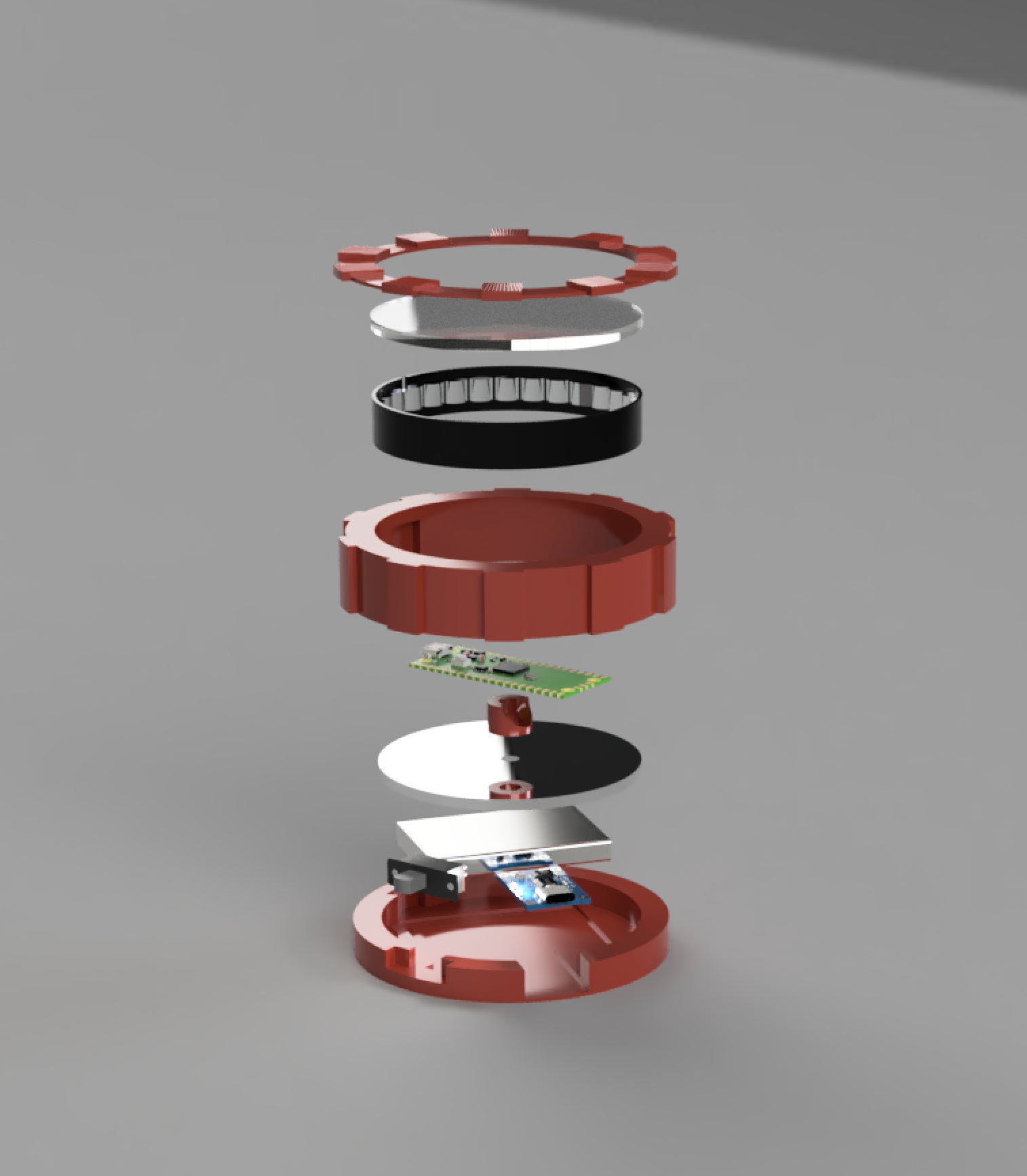
Construct the hardware
3D-printed parts
Four 3D-printed pieces are required to house all the component parts: the back, main body, Pico stand, and front. We will glue them together to form the complete assembly. You can download the 3D print files for free at printables.com. Print them using any FDM (Fused Deposition Modelling) 3D printer with a build area of 70mm2 or larger. We recommend you use a material that is easy to print with, such as PLA or PETG filament.

Cutting and preparing the acrylic discs
For this project, you will need two acrylic discs 3mm thick and 70mm in diameter, one of which will require a hole approximately 5mm in diameter for wiring. If you have access to a laser cutter, making these is straightforward. Otherwise, it might be time to dig out your old pencil case and find a pair of compasses.
Using a jigsaw, cut out a 70mm circle and neaten up the edges with sandpaper or a file. The final discs don’t need to be absolutely flawless, since the subsequent steps will cover any minor imperfections. One disc should be drilled with a 5mm hole in the centre to allow wiring to pass through later:

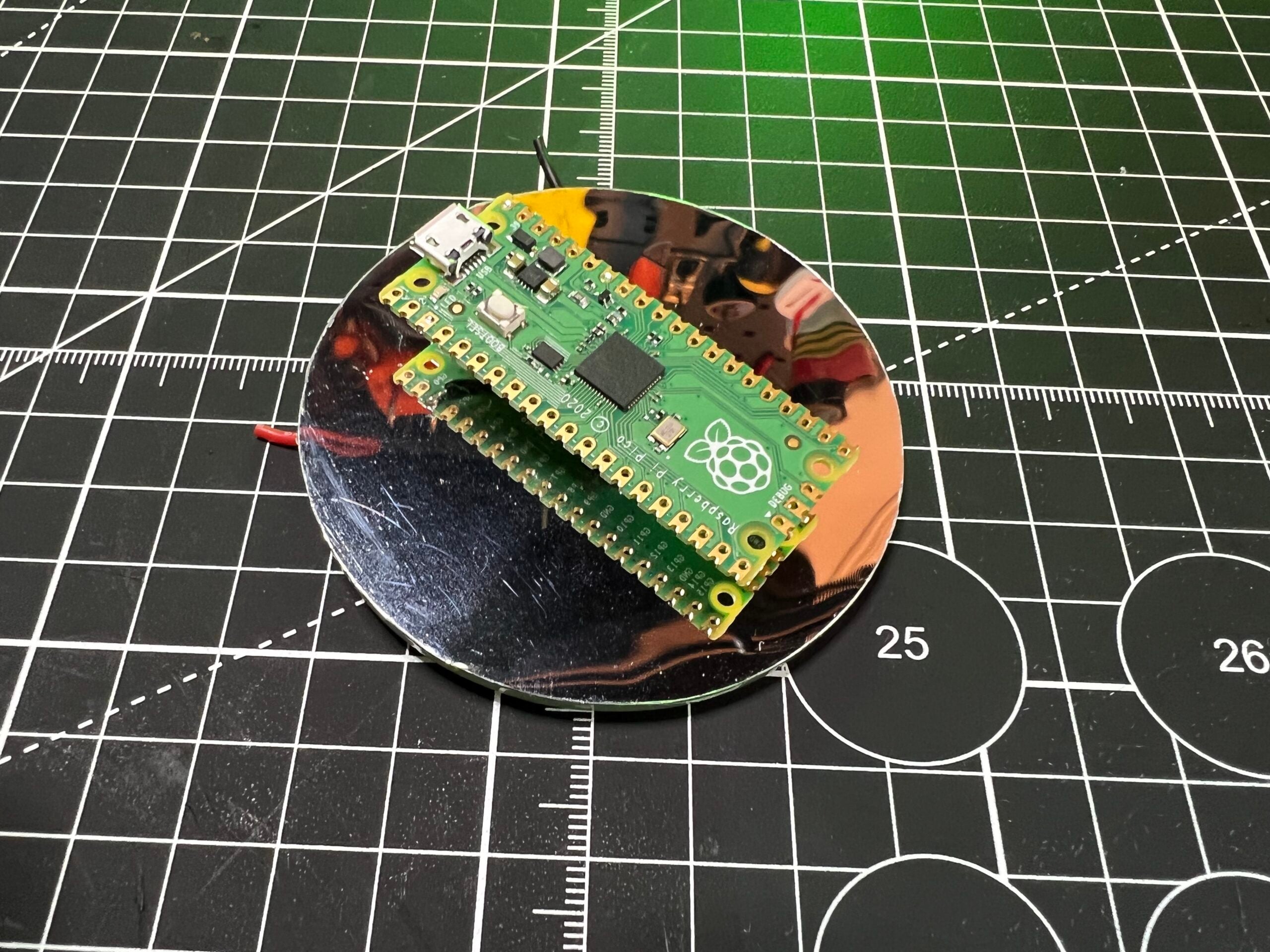
Mark a 70mm circle on your flexible adhesive mirror tile and another on your one-way mirror self-adhesive film. To make them perfectly round, cut them out using scissors. Ensure that you remove all the protective layers from your acrylic discs and then peel the adhesive backing from your mirror sheets in turn. Attach the circle of mirror tile sheet to the disc with the hole, which will be used to mount your Pico, and the circle of one-way mirror film to the other disc.
Wire and solder the electronics
The Arc Reactor base contains the rechargeable battery, on/off switch, and USB-C charging board, all of which you need to glue into place inside the 3D-printed cutouts. At this stage, you need to do some cutting of wires, stripping and soldering. Use the photograph below as a reference to ensure that:
-
the positive and negative wires from the battery are soldered to the correct USB-C charging board positive and negative inputs
-
the positive output from the board is soldered to the centre pin of the sliding switch
You can solder the positive wire from the switch to either of the two outer switch terminals:

Next, solder three wires directly to the back of your Pico. The wires should be long enough to complete the wiring circuit later in the assembly process: about 20cm. To provide power to your Pico:
-
connect a red wires to the pin marked VBUS
-
connect a black wire to the pin marked GND
Solder a third wire, shown here in blue, to the pin marked GP28. Our MicroPython script uses this pin to communicate with the LEDs:

LED strips usually come pre-wired, but their joints are often bulky, so we will make our own wiring loom. Using a pair of scissors, remove any pre-existing wiring and cut a strip of 31 LEDs. Be sure to cut along the line between LEDs:

The strip is also marked with arrows to show the correct current direction, + symbols for the positive wire, 0 for the data wire, and G for the negative or ground wire. When cutting, be sure to snip down the middle of each solder pad. If you’re not careful, it could be tricky to solder the wires to the pads.

Solder three more wires, also approximately 20cm in length, as shown in the photo above: red for positive, blue for data, and black for ground. You may find it more convenient to solder from the rear of the strip.
Assembly
-
Feed the three wires attached to your Raspberry Pi Pico through the small 3D-printed Pico stand.
-
Thread the wires through the hole in the mirrored disc.
-
Glue the stand to the underside of your Pico and to the reflective side of the disc.
-
Ensure that Pico sits above the surface of the mirror on the stand to achieve the 3D infinity effect:
-
Place the disc with the one-way film in the main 3D-printed body.
-
Glue the front ring to the body. The front ring will conceal any minor imperfections in the disc.
-
Stick the strip of 31 LEDs around the inside of the 3D-printed body, ensuring that the wiring and connections are aligned with the gap in the body, so that you can easily pass the wires around the side of the disc on which your Pico is mounted. Most LED strips have self-adhesive backing, which makes this straightforward. Refer to this diagram to see how everything will fit together:
Royale with Pico cheese -
With Pico already glued to its mirrored disc, you can now pair it with the main body housing the LEDs and the one-way mirror, and with the base containing the battery, charging board, and switch. Make sure that you have the ends of all your wires threaded through to the Arc Reactor base.
-
Solder (trimming any excess wire length as necessary):
-
the two blue data wires together
-
all three red positive wires together
-
all three negative ground wires together
-
Don’t forget to insulate your joins with heat shrink tubing or tape!
Final checks
Before you glue the pieces together and make it final, check that everything is working as expected and that your LEDs are lighting up by sliding the switch. Check that the charging board functions by attaching a USB-C charger or battery pack: a small LED should illuminate when it’s charging.
Finally, glue the parts together.
Congratulations. You have finished assembling your Arc Reactor!
Moving forward
Upgrades! Everyone enjoys an upgrade, especially Iron Man. Why not use a Raspberry Pi Pico W running a webserver to control your LEDs wirelessly from a browser on your smartphone? Or you could add a touch of paint and stick some velcro to the back of the reactor so that you can wear it on your chest like Tony Stark.