$ ssh <username>@pi-weather.localBuild your own weather satellite receiving station
All tutorials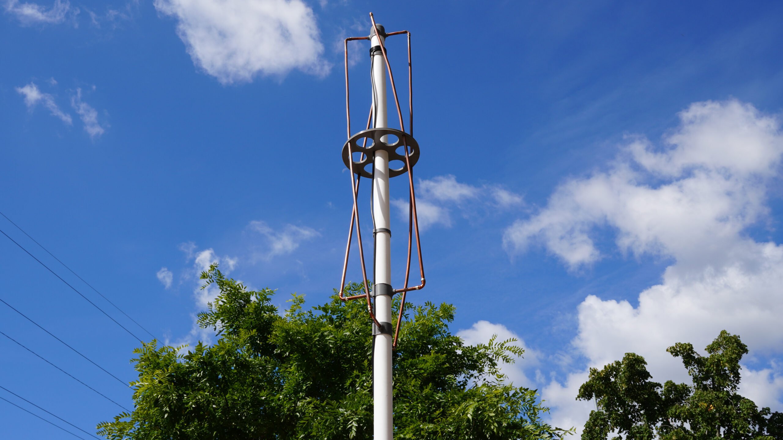
You can create all kinds of fun projects when you pair a Raspberry Pi with a low-cost USB Software Defined Radio (SDR). An SDR is essentially a radio wave receiver that can pick up signals from a variety of frequencies, including digital television, AM, FM and DAB radio broadcasts, and aircraft transponders.
This tutorial focuses on the signals sent by the many weather satellites orbiting planet Earth. We will create our own antenna in order to receive those signals, then we will use open source software called raspberry-noaa-v2 to decode those signals on a Raspberry Pi.
Supplies
-
Raspberry Pi 4
-
suitable Raspberry Pi power supply (see the power supply documentation for details)
-
microSD card
-
adapter to connect your microSD card with your usual computer
-
USB Software Defined Radio (SDR) receiver (we used this NESDR Mini TV28T v2) USB RTL-SDR, DVB-T & ADS-B Receiver Set)
-
Raspberry Pi 4 model B case
-
5 metres of 8mm Microbore Copper Tube (we used this these, sold in a pack of 10)
-
MCX Male to BNC Female RG316 Low Loss Pigtail Adapter 23.5cm Cable
-
BNC Male to BNC Female RG58 Coax Cable (the length of this cable depends on where you place your antenna. We used this 10 metre length
-
1.5 metre length of white plastic 40mm waste pipe
-
File or sandpaper
-
Solder
-
4 x 2mm by 8mm self tapping screws
For the initial SD card setup, you will need:
-
Another computer connected to your network. We’ll refer to this as your usual computer to distinguish it from the Raspberry Pi computer you are setting up as a weather receiving station.
Choose the right Raspberry Pi
Version two of the raspberry-noaa software was developed and tested with a Raspberry Pi 4; we can’t guarantee compatibility with older Raspberry Pi models. For this tutorial, we’ll use a Raspberry Pi 4 Model B.
Tools required for the antenna build:
note
You can construct the antenna without using 3D printed parts, but a 3D printer makes the build process much simpler. 3D printed parts should eliminate alignment issues that can present a challenge for some makers.
tip
If you plan on placing your antenna outside, we recommend ABS filament due to its greater resistance to direct sunlight than other materials.
-
A 3D printer.
-
Hand saw or chop saw (for cutting the waste pipe to length)
-
Hacksaw (for cutting 8mm copper tube to length)
-
Glue (suitable for plastics and wood)
-
Small screwdriver (for self tapping screws)
-
8mm drill bit (any general purpose drill bit should do)
-
Wire cutters
-
Tape measure
-
Pencil
3D printed parts
Download this tutorial’s .stl files for free from printables.com/model/549255-weather-satellite-receiving-station-antenna.
Antenna construction
We’ve updated a project by Steve Blackmore to make our own antenna.
We will make a Quadrifilar Helix Antenna (QHA) to receive weather satellite radio signals. The key feature of a QHA is the helical (spiralled) shape, which allows the antenna to capture signals from all directions. The term "Quadrifilar" means it has four conductors (wires). We’ll wrap the wires around the helix to provide four separate paths for the signal to travel. The QHA is a circularly polarised antenna, so it can receive signals in horizontal and vertical planes. This allows the antenna to maintain efficiency regardless of the antenna’s orientation.
Our antenna consists of a single plastic mast with 3D-printed parts to hold the copper conductors in their correct orientation. We’ll ultimately connect the antenna to the USB SDR connected to our Raspberry Pi.
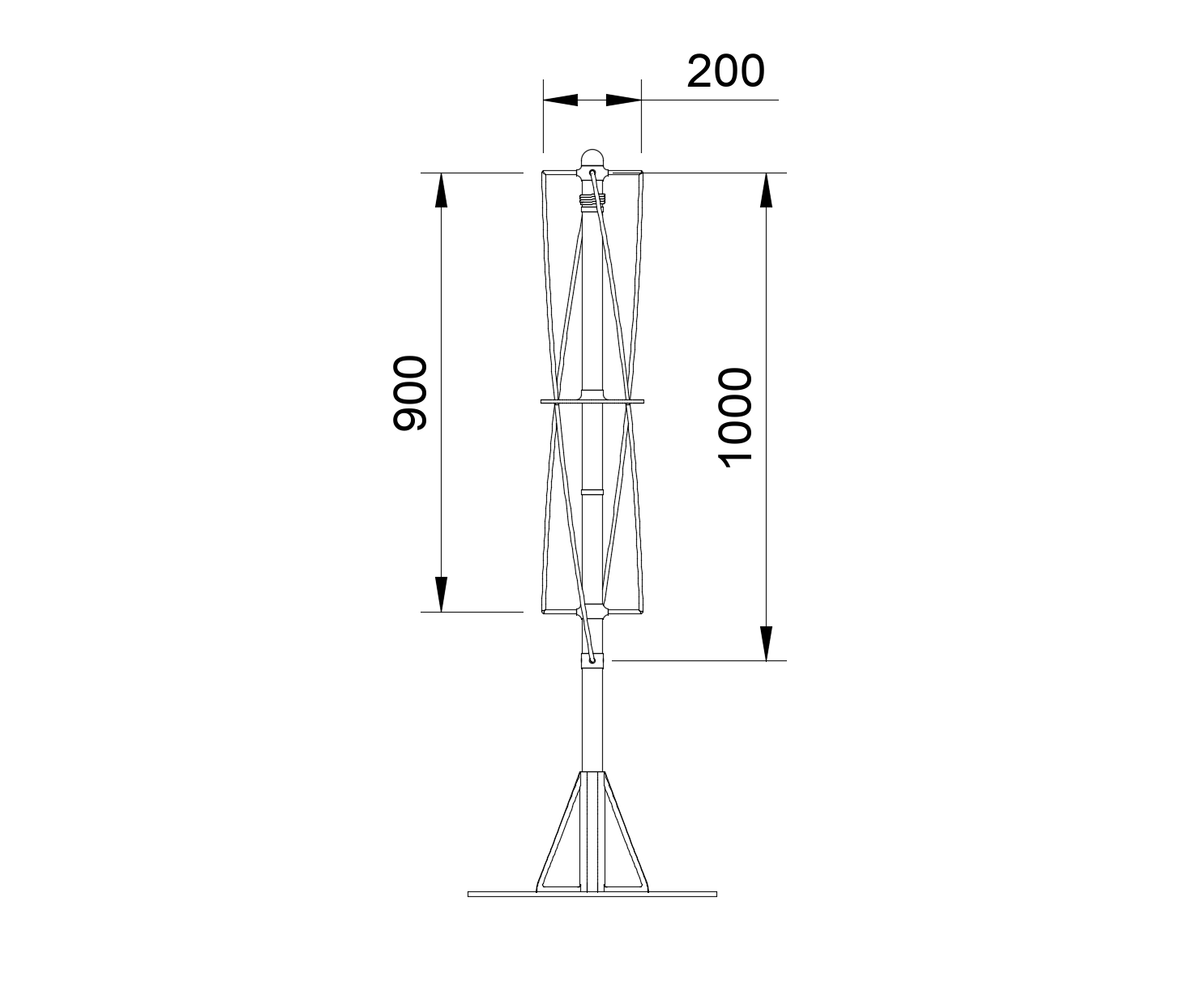
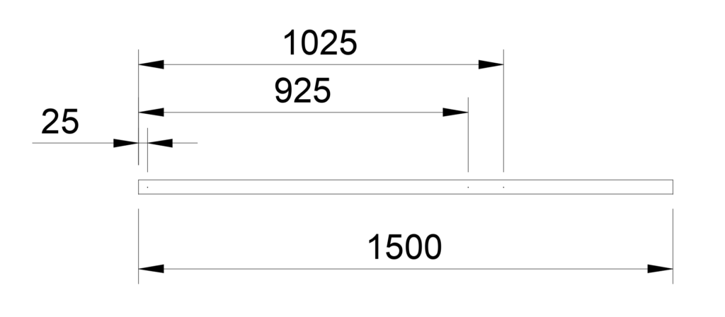
The following diagram illustrates the exact dimensions that are important to the finished antenna:
Print parts
tip
The STL files for this project are available for free at printables.com/model/549255-weather-satellite-receiving-station-antenna.
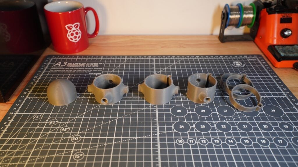
First, let’s print out the supports.
Print the pieces using ABS filament using the right settings for your printer. We printed ours using a 0.8mm nozzle, 0.4mm layer height, and 100% infill for maximum strength.
note
The mounting method and location of your antenna is up to you, but we’ve included a simple test stand for you to print and glue to a board for basic installation.
Center mast
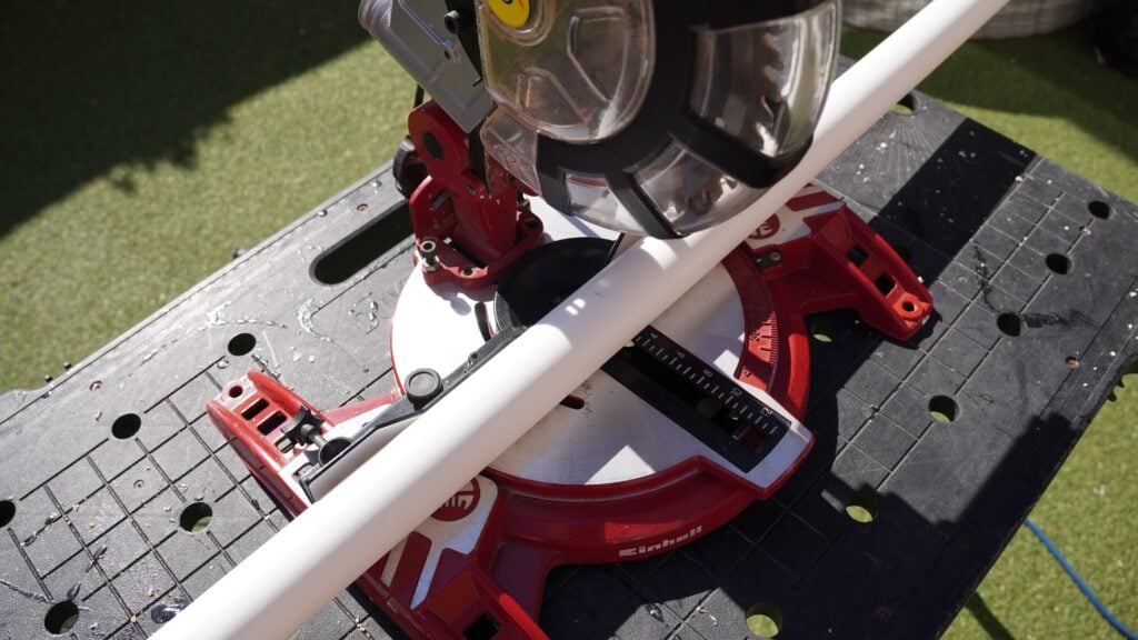
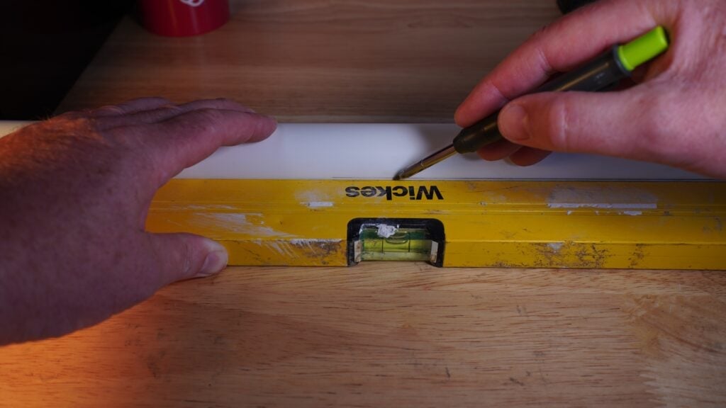
Measure and cut a 1.5 metre length of 40mm waste pipe to make the mast. Then, using a suitably straight edged item — like a long spirit level — draw a line down the length of the mast.
tip
Hold the pipe firmly in place on a flat surface with the straight edge against the pipe to accurately draw the line down the middle of the pipe.
Next, measuring from one end of the pipe, mark the line at three points: 25mm, 925mm, and 1025mm. This is where we’ll mount the conductors.
note
Accurate measurements maximise the efficiency, gain, and radiation pattern of your antenna. Even small deviations from the intended dimensions can result in significant degradation of the antenna’s performance!
Conductors
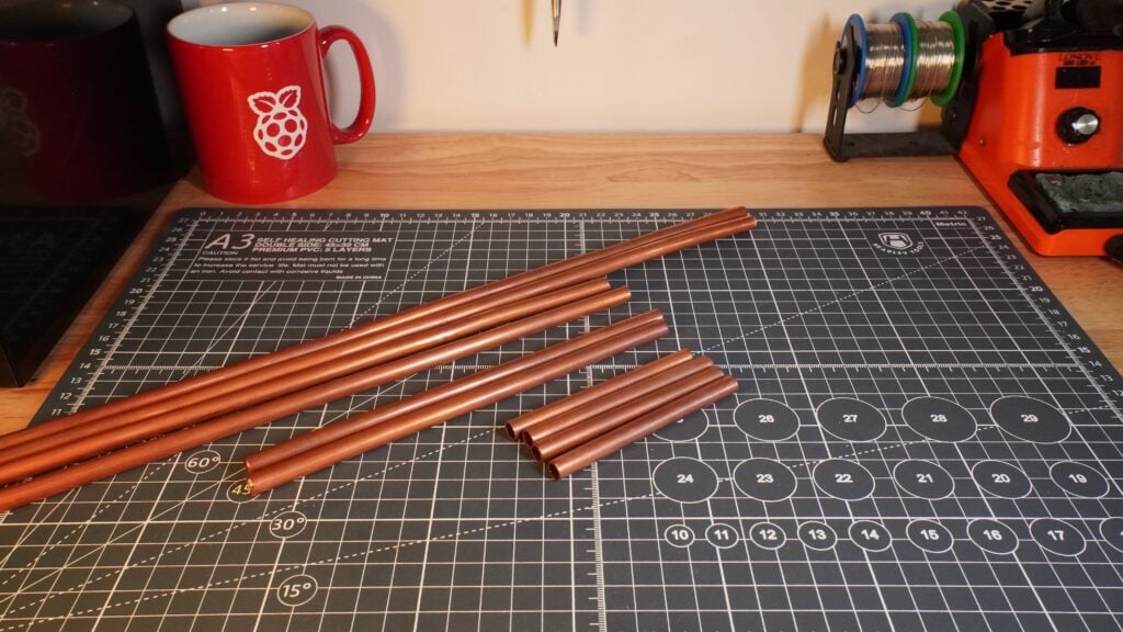
Our conductors are made from 8mm microbore copper tubing. Using a hacksaw, cut the tube to the following lengths:
-
Four 85mm lengths for the top horizontal elements
-
Two 185mm lengths for the bottom horizontal tubes
-
Two 898mm lengths for the short helix elements
-
Two 995mm lengths for the long helix elements
tip
When you’ve cut all the pieces to length, roll them between two sheets of flat wood board, such as MDF or plywood, to straighten out any bends in the pipes.
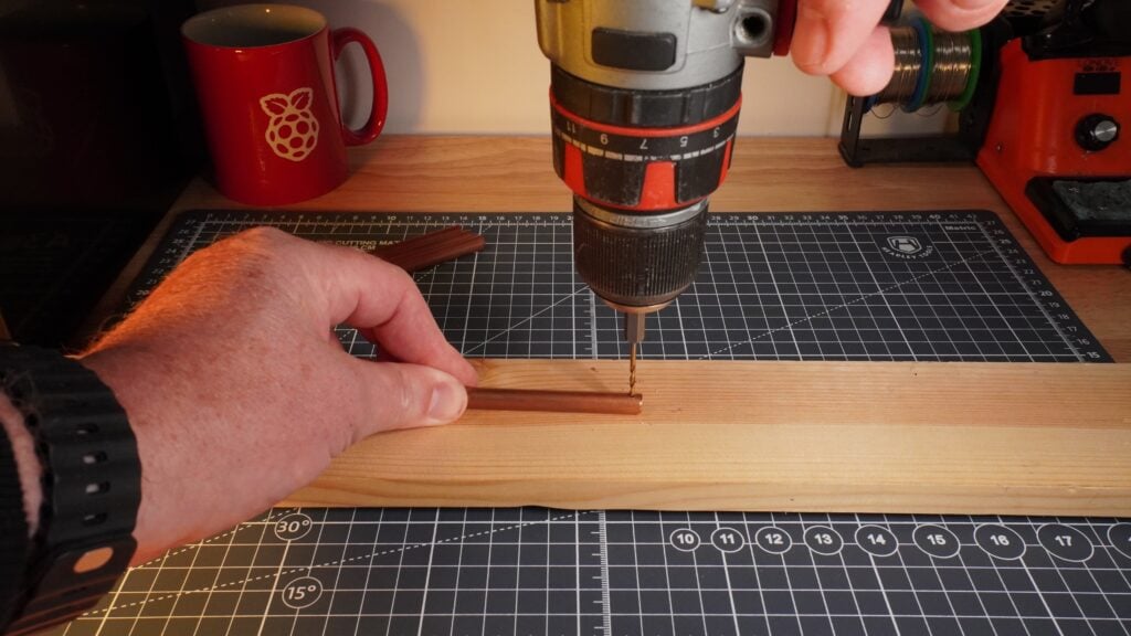
Take the four 85mm lengths and drill a 3mm hole approximately 5mm from one end of each length. These holes are for the self-tapping screws that will hold the wiring in place.
Assembly
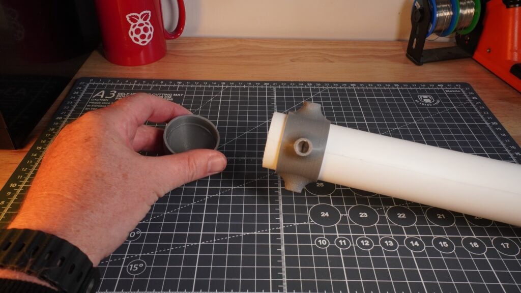
Take the 3D-printed top conductor ring and slide it onto the top of the mast, lining up one of the four holes with the first mark you made 25mm from the end. Align the mark exactly onto the centre of the hole; this should leave 10mm of mast exposed at the end.
tip
The cap is designed to only fit 10mm onto the mast, so you can push fit the cap on the end.
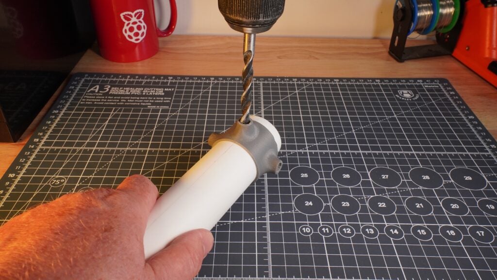
Next, use the ring to align the drill bit and drill four 8mm holes in the mast 90 degrees apart from each other:
Take the lower conductor ring and slide it into position at the mark you made at 925mm.
Do the same with the bottom ring at the 1025mm mark.
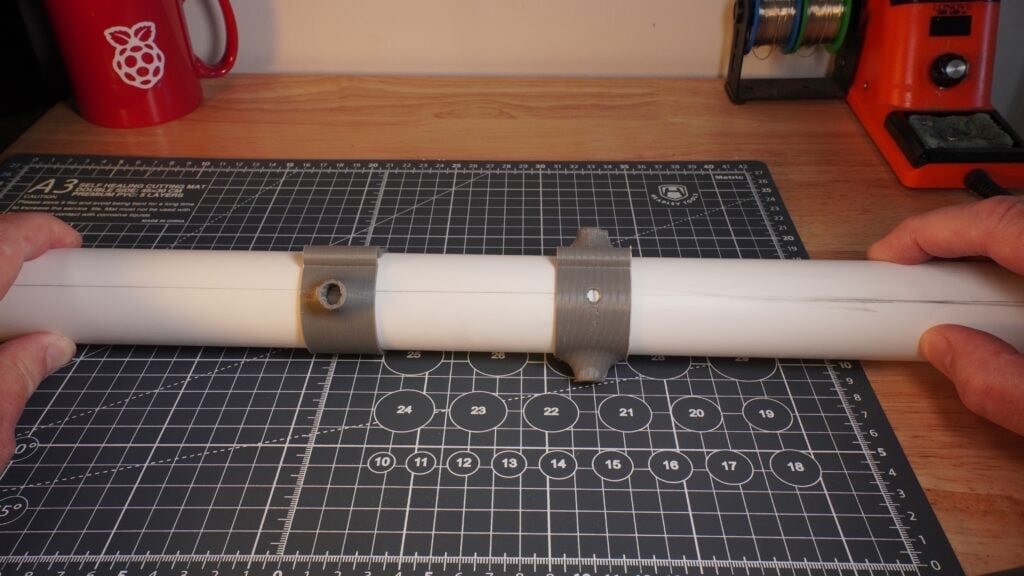
Take extra care during this stage to make sure you correctly align the 3D printed pieces:
-
align the 925mm ring with the element hole, just like the upper conductor ring
-
align the bottom ring with the small, flush alignment hole
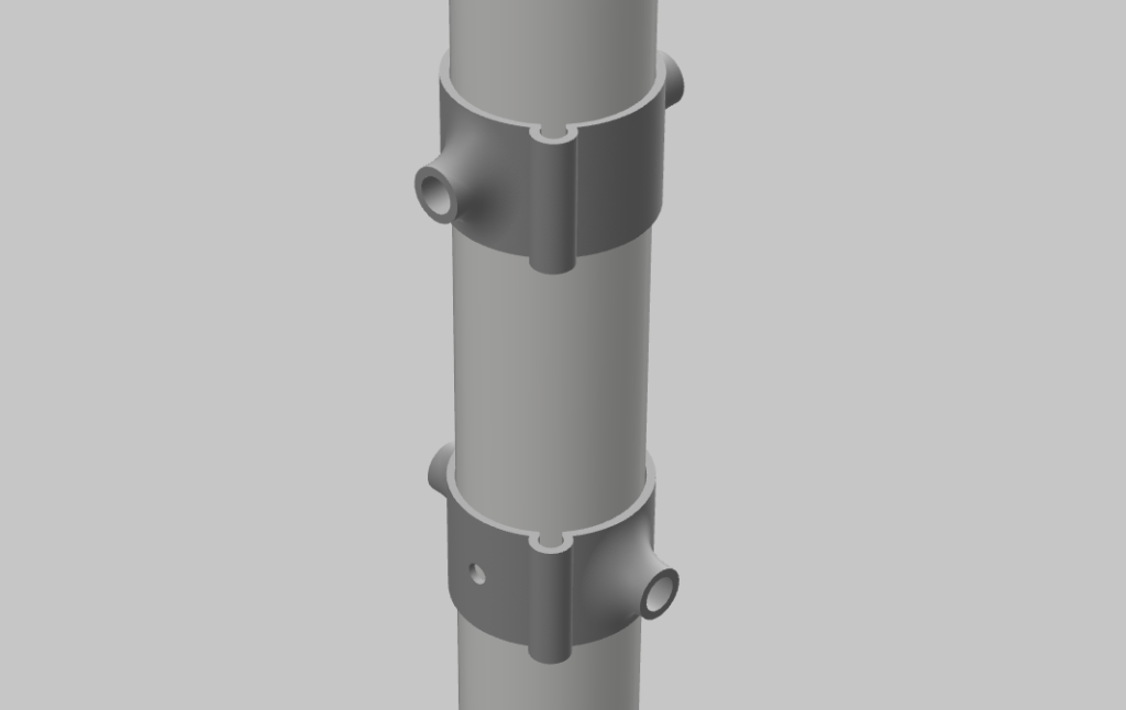
When you are happy with all your measurements and positioning, drill two 8mm holes in the middle and lower rings.
Next:
-
push the four 85mm copper tubes into the top ring
-
push the two 185mm copper tubes into the bottom ring
Your tubes should extend 200mm from the centre of the pipe on either side:

Taking into account the helix shapes, the two long helix elements will be 1012mm long with the corner pieces attached, and the two short helix elements will be 913mm long. Combining those lengths with the helix shaping gives the measurements shown in the previous side view.
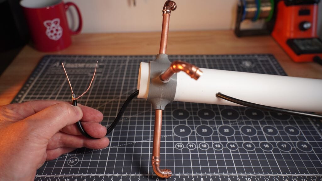
Next, drill a 7mm hole approximately 100mm from the end of the mast inline with the cable management holes in the lower conductor rings.
Take your RG58 coax cable and cut off the male connector end — we won’t need it.
Feed the cable into the mast through the drilled hole and out of the end.
Use your wire cutters to strip back the outer plastic jacket on the exposed end by about 50mm. Then, wind the outer woven metal braided wires into one wire.
Remove the insulation layer surrounding the central solid copper wire.
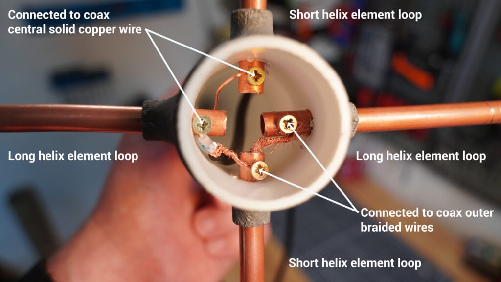
Next, pass the central solid copper wire in the RG58 coax cable through the drilled holes at the end of one of the long helix element loops. Wire it all the way through the end of one of the short helix element loops.
Pass the outer woven metal braided wires through the remaining holes on the other short helix element loop and long helix element loop.
Hold the wires in place with the four self-tapping screws:
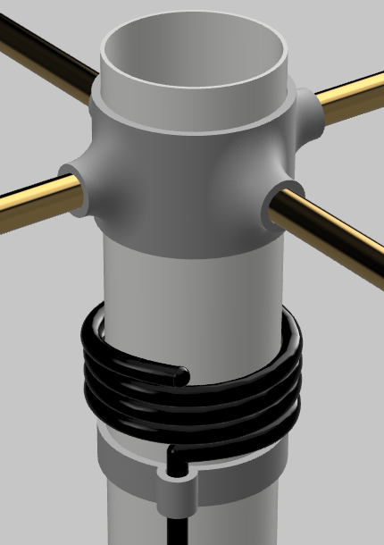
Finally, we need to create a balun: a device that helps connect balanced antennas to unbalanced coaxial cables by converting the two transmission line configurations. This plays a crucial role in maintaining signal quality, reducing interference, and optimising the performance of any antenna.
Wind the coax cable around the mast four times, then place a cable management ring just below it to hold it in place. To do this, remove the two lower conductor 3D printed rings attached earlier (this is temporary, we’ll put them back on in the next step).
tip
Add a small amount of glue to keep the coax cable in place.
Now your balun should look like this:
Slide on the mid ring, another cable management ring, and replace the two lower rings.
Slide the two 185mm lengths of copper back into place.
Push-fit four of the solder ring elbows.
Attach the two long and two short helix elements into place.
tip
Bend the tubes slightly if needed to make sure they fit. The mid ring will help you create a smooth shape. Don’t forget to pop the cap on!

Look down at the antenna from the top. It should appear circular in shape:
Now is a good time to remeasure (from the center of each element):
-
The two long helix elements (with the corner pieces attached) should measure 1012mm long.
-
The two short helix elements should measure 913mm long.
tip
Some elbow joints are different from others, so you may have to trim the tubes to get the correct lengths.
When you’re happy with the placement, use a small amount of solder and a blow torch to weld all 16 connections between the tubes and corner joints.
If you chose to 3D print the antenna stand, slide the mast into place and you’re done!
If you opted to use your own antenna stand, it’s time to figure out another way to mount it.
Regardless of the method you use, position it with an elevated, clear, and unobstructed view of the sky.
Configure your Raspberry Pi
To begin, follow the Getting Started documentation to set up your Raspberry Pi. For your operating system, choose Raspberry Pi OS Lite (32-bit) to run headless (without a mouse and keyboard).
During the OS customisation stage, edit settings as follows:
-
Enter a hostname of your choice (we suggest
pi-weatherfor this tutorial) -
Enter a username and password; you’ll need these later to authenticate
-
Check the box next to Configure wireless LAN so your Pi can automatically connect to Wi-Fi
-
Enter your network SSID (name) and password; you can find these in your Wi-Fi settings or on a sticker on your router
-
Check the box next to Enable SSH so we can connect to the Pi without a mouse and keyboard
Remotely connect to your Raspberry Pi
SSH allows you to wirelessly connect to your Raspberry Pi, eliminating the need for a keyboard and mouse. It’s perfect if your Raspberry Pi is located in a hard-to-reach location, like behind a train times display.
note
To SSH into the Raspberry Pi, you’ll use the hostname you set in Imager. If you have issues connecting using this method, you may want to use the Raspberry Pi’s IP address instead.
For more information about finding your IP address and remote accessing your Raspberry Pi, see the remote access documentation.
Connect via SSH
Open a terminal session on your usual computer. To access your Raspberry Pi via SSH, run the following command, replacing <username> with the username you chose in Imager:
The first time you do this, confirm that you want to connect. When asked, use the password you created in Raspberry Pi Imager:
$ ssh <username>@pi-weather.local
The authenticity of host 'pi-weather.local (fd81:b8a1:261d:1:acd4:610c:b069:ac16)' can't be established.
ED25519 key fingerprint is SHA256:s6aWAEe8xrbPmJzhctei7/gEQitO9mj2ilXigelBm04.
This key is not known by any other names
Are you sure you want to continue connecting (yes/no/
[fingerprint])? yes
Warning: Permanently added 'pi-weather.local' (ED25519) to the list of known hosts.

<username>@pi-weather.local's password:
Linux pi-weather 6.1.21-v8+ #1642 SMP PREEMPT Mon Apr  3 17:24:16 BST 2023 aarch64

The programs included with the Debian GNU/Linux system are free software;
the exact distribution terms for each program are described in the
individual files in /usr/share/doc/*/copyright.

Debian GNU/Linux comes with ABSOLUTELY NO WARRANTY, to the extent
permitted by applicable law.
Last login: Fri Oct 27 09:41:00 2023
<username>@pi-weather:~ $
Now that you’ve connected to your Raspberry Pi, run two commands to make sure that all of your packages are up to date:
$ sudo apt update
$ sudo apt full-upgrade
Once the package update commands finish running, reboot your Raspberry Pi to allow all changes to take effect:
$ sudo rebootRunning this command will disconnect you from the Raspberry Pi SSH session. Wait a few seconds for your Raspberry Pi to reboot, and enter the ssh connection command again to reconnect to your device.
tip
On most terminals, press the Up arrow key, then the Enter key to re-run the most recent command.
Connect the antenna to your Raspberry Pi
Attach the SDR dongle to any of the four available USB ports on your Raspberry Pi and attach the MCX male to BNC female adaptor into the side of the SDR. You should feel a reassuring click when the cable is inserted correctly. Attach the other end of the BNC connection to your antenna’s RG58 coax cable BNC female connector.

Install software
Now that your Raspberry Pi is up and running and your antenna is ready to use, let’s install raspberry-noaa-v2. Open a terminal and run the following commands to install raspberry-noaa-v2.
First, install git, a popular version control system:
$ sudo apt install git -yNext, navigate to your home directory and use git to download raspberry-noaa-v2:
$ cd
$ git clone https://github.com/jekhokie/raspberry-noaa-v2.git
Finally, open the configuration file for raspberry-noaa-v2 with the nano text editor:
$ cd raspberry-noaa-v2/
$ cp config/settings.yml.sample config/settings.yml
$ nano config/settings.yml
Configure Raspberry NOAA V2
First, configure your antenna location.
You can obtain your latitude and longitude coordinates from LatLong.net, either by searching for a place name or by navigating your way around the interactive map. Find your coordinates to four decimal places (for example, 52.2048, 0.1304 is close enough to get you to a cracking pub in Cambridge).
Your altitude can be found using whataltitude.com. Replace 0.0 with your altitude in metres.
Change the default values in the configuration file to match your location:
# base station configurations
#   latitude: south values are negative
#   longitude: west values are negative
latitude: 52.2048
longitude: 0.1304
altitude: 42.0
Next, configure your time zone.
You can use Wikipedia to find your UTC offset.
Change the default values in the configuration file to match your time zone:
# time zone offset from UTC (for example, '-5' for US Eastern)
timezone_offset: -5
Next, update the rest of the locale settings.
Visit php.net/manual/en/timezones.php, click on the link for your region, and find your nearest time zone in the list.
Choose a preferred language from the options provided by Raspberry NOAA V2.
Change the default time zone and language values to match your time zone and preferred language:
# locale settings for timezone and language
#   timezone: see https://www.php.net/manual/en/timezones.php
#   lang_setting: see the 'webpanel/App/Lang' folder for available
#* * * *  languages (2-letter filename - e.g. ar, bg, de, en, es, nl)
timezone: America/New_York
lang_setting: en
Finally, update the web server name setting.
We chose pi-weather as our hostname, so we should update the web server name value to match that hostname:
web_server_name: pi-weather.local
enable_non_tls: false
web_port: 80
enable_tls: true
web_tls_port: 443
cert_valid_days: 365
lock_admin_page: false
admin_username: 'admin'
admin_password: 'admin'
web_passes_date_format: 'd/m/Y'
web_datetime_format: 'd/m/Y H:i:s'
You can also change the date format settings to match your preferred style: the above example formats dates in the UK style. To save your changes, press CTRL+X, then Y, then Enter to save your changes to the configuration file.
Now we can install and automatically start the Raspberry NOAA V2:
$ ./install_and_upgrade.shThis command could take a few minutes to run.
Use your receiving station
Using your usual computer, open a browser session and visit https://pi-weather.local:443. You should see the Raspberry NOAA V2 web page.
tip
The first time you do this your browser may warn that you are visiting an insecure site. This is normal, and you can agree to proceed.
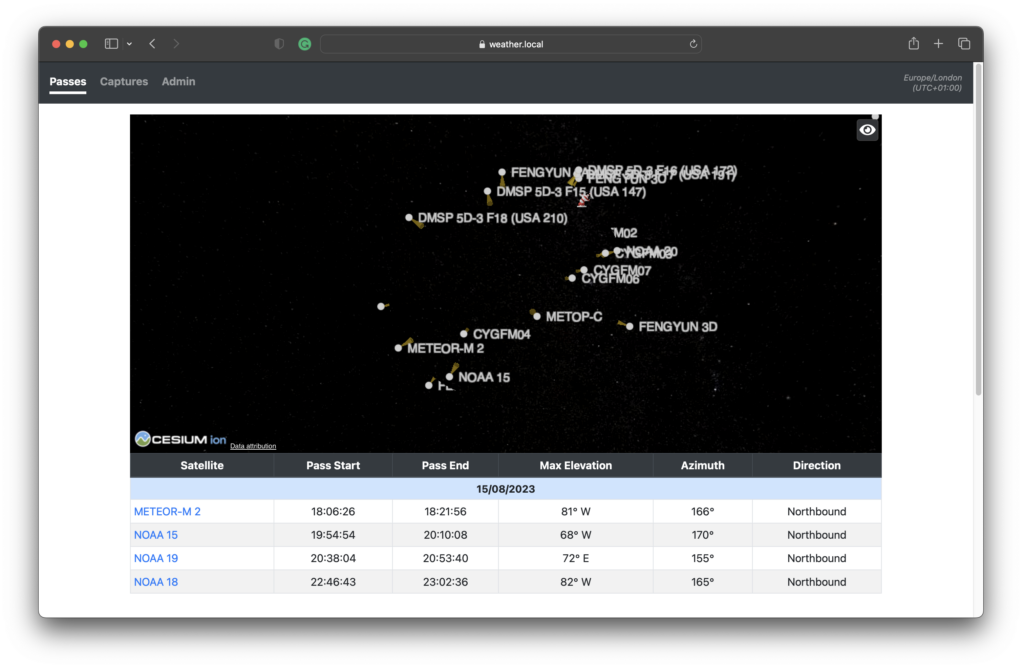
You will see a live view of weather satellites orbiting the planet and a list of satellites due to pass over your area.
To make this page easier to understand, click the eye icon in the top right corner of the screen (marked in red below) to change view options:
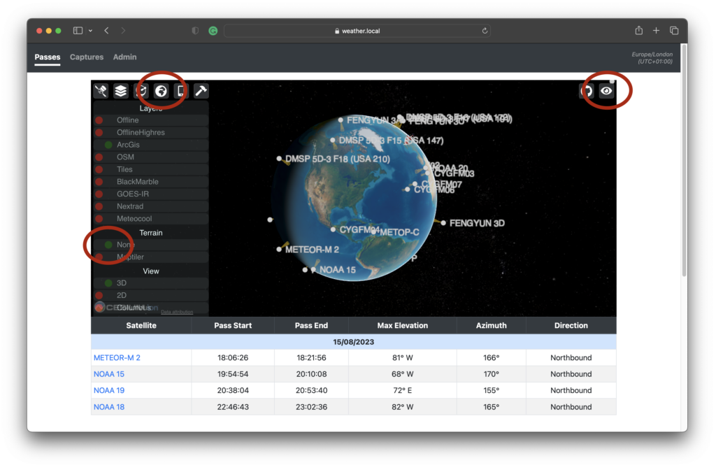
Click the globe icon to the left to open up more options. Under Terrain, select None to show the globe.

Left click and move your mouse around to rotate the globe.
You should see satellites orbiting slowly across the planet, and a small red icon that marks the location of your ground station.
The list under the globe shows all of the satellites due to pass over your ground station. Greyed out lines are historic flyovers. Raspberry NOAA V2 records when a weather satellite flies over and updates the list of upcoming satellites every night.
Once you have received some data, navigate to the Captures tab:

Here you will see a list of all satellite passes recorded. Click on any one for more details.

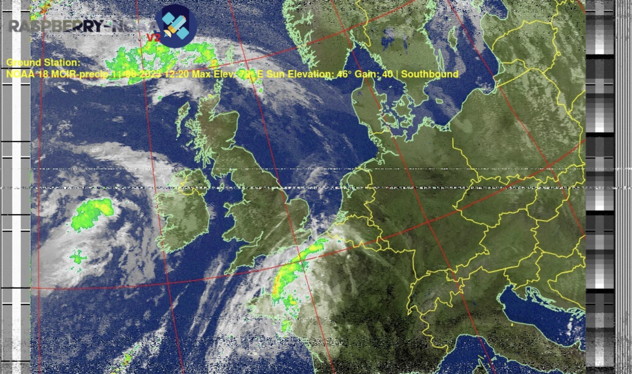
Each picture represents specific data collected from a satellite pass.
You can click Information in the top right for more details.
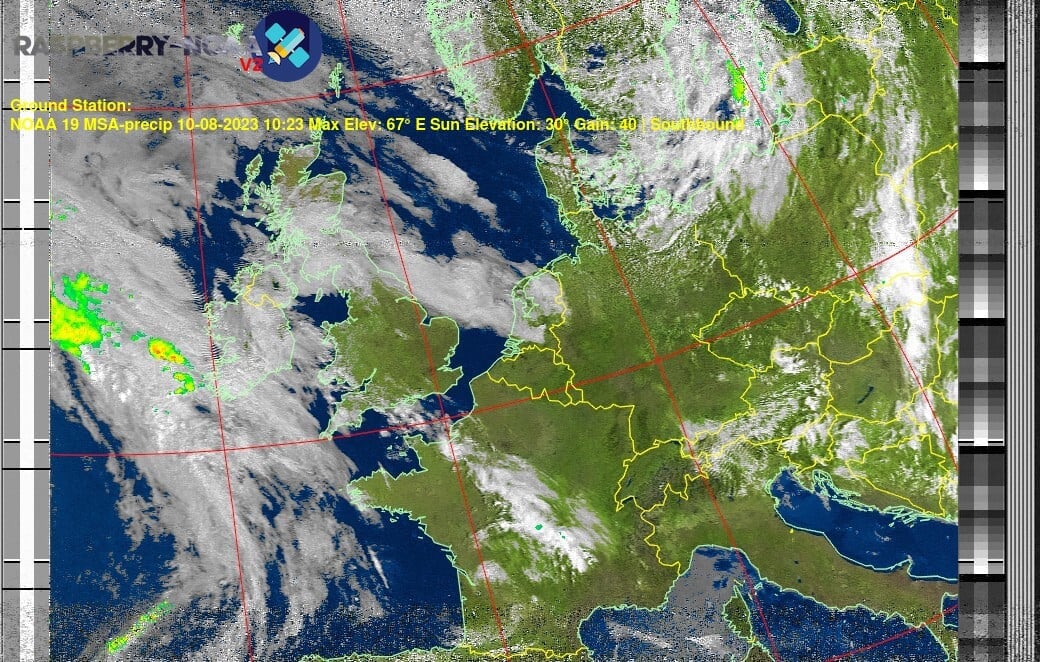
For example, the following image shows cloud cover with enhanced emphasis on rainfall shown in bright green and yellow:
And the following image shows temperature:
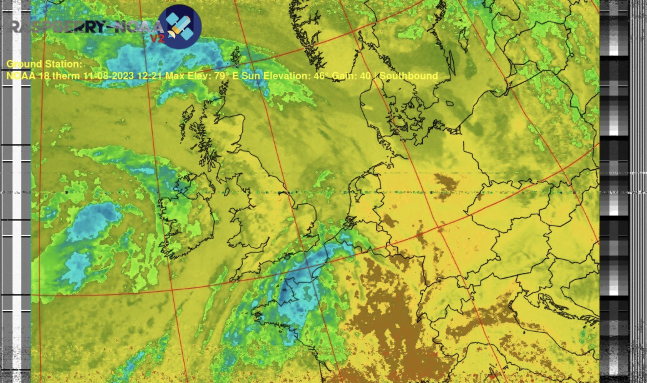
Different satellites produce different quality images.
The following capture recorded a poor-quality image due to the antenna being indoors:
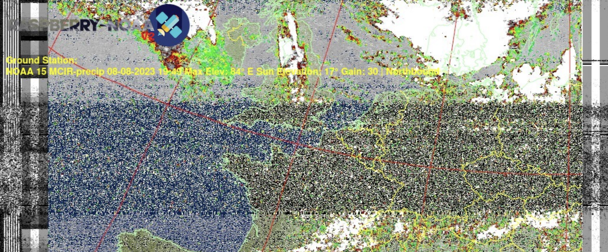
Image quality depends on many factors:
-
how directly a satellite passes overhead
-
antenna placement
-
configuration settings like gain
tip
Try experimenting with different antenna designs, receiver configurations, and software settings to improve your station’s performance. Small adjustments can significantly improve reception: for example, changing the gain setting for each satellite from 30 to 40 improved our images!
Moving forward
Enhancing your satellite-tracking skills can be a rewarding challenge. Even though this tutorial focuses on weather satellites, the principles you’ve learned apply to other satellite types, like amateur radio satellites or CubeSats. Your weather satellite receiving station is not just a standalone project: it can help you deepen your understanding of space and technology.
Consider sharing your experiences and findings with the maker and amateur radio communities. Social media platforms, blog posts, and forum discussions are excellent ways to showcase your work, share ideas, and inspire others.