How we added interlaced video to Raspberry Pi 5 DPI
The very first Raspberry Pi had a composite video output, and all models with a 40-pin header have a display parallel interface (DPI) output. With some external components, DPI can be converted to VGA or RGB/SCART video. Those analogue interfaces are still in demand for retro media and gaming.
Raspberry Pi 5 was a big step up in processing power, but unlike previous models, its DPI block didn’t support interlaced video (which isn’t really part of the DPI standard), so it couldn’t send full-resolution RGB to a CRT television. Until now.

What is interlaced video?
Early TV systems worked by scanning the image from (usually) left to right, top to bottom. There were tradeoffs between frame rate, resolution, and radio bandwidth demands. With interlace, the frame is divided into odd and even lines. The odd lines are scanned from top to bottom, followed by the even ones. This reduces flicker and improves smoothness without increasing bandwidth. The two parts of each frame are called ‘fields’.

Analogue TVs don’t need to do anything special to tell which field is which. Provided the horizontal scanning rate is an odd multiple of half the vertical rate, the scan-lines will fall into the right places on the screen. A key feature of interlaced video is that vertical synchronisation pulses can occur in two different phases, relative to the horizontal ones.
The problem to solve
To generate interlaced video, we had to do three things:
- Get DPI to emit fields (even or odd lines of a frame-buffer) instead of frames
- Time those signals so they will be in the proper arrangement for interlace
- Generate appropriate sync pulses
The first part is easy. By changing an address and doubling the ‘stride’ between lines, we can arrange for DPI to read and display just the even or odd lines of a frame-buffer. We use an interrupt to switch back and forth between even and odd fields, 50 or 60 times a second.
The second problem is solved by hacking the DPI peripheral. If we time it just right, we can change its configuration on the fly, so that every second frame — every second field, I should say — gets one extra blank line at the end. The extra line should come after an upper field and before a lower one.
The third problem is harder. RP1’s DPI has no way to make vertical sync pulses start midway through a line.
PIO to the rescue
Like Raspberry Pi’s RP2040 and RP2350 microcontrollers, our RP1 chip has a Programmable Input/Output (PIO) block. It can generate many kinds of real-time waveforms. We recently added PIO support to our version of the Linux kernel, exposing it to device drivers and user programs.
Here, PIO snoops on DPI’s horizontal sync (HSync) and data enable (DE) pins to generate vertical sync (VSync). Two of PIO’s four state machines (SMs) are used: one SM serves as a timer, generating an ‘interrupt’ at the start and middle of each line. The other SM finds the start of the vertical blanking interval (the first line without DE), then counts half-lines to work out when to start and end the VSync pulse. Finally, it samples DE again to detect the extra blank line, to ensure it has the correct field-phase for next time.

There are some gotchas: the DE signal must be output on GPIO1, whether it’s used or not. PIO is not synchronised to the DPI clock and its VSync output can jitter up to ±5 ns. That isn’t significant at standard-definition TV rates, but it could be a problem at higher resolutions! Finally, the sync fixup consumes most of RP1’s PIO instruction memory, so PIO can’t be used for other cool things at the same time as generating interlaced DPI.
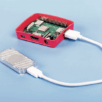
If you have a Raspberry Pi 5, a VGA666 HAT, and a VGA monitor that can run at 50Hz TV rates, you could test it by adding this to config.txt:
dtoverlay=vc4-kms-dpi-generic
dtparam=clock-frequency=13500000
dtparam=hactive=720,hfp=12,hsync=64,hbp=68
dtparam=vactive=576,vfp=5,vsync=5,vbp=39
dtparam=vsync-invert,hsync-invert
dtparam=interlaced
Make sure you’ve upgraded to the latest Raspberry Pi OS. Note that the above configuration will output DPICLK (which isn’t used) on GPIO0, and DE (which PIO needs to snoop on) on GPIO1, and precludes the use of I2C/DDC on those pins. Other HATs might need a custom overlay, to enable DE output on GPIO1 (where safe to do so).
Composite sync too
VGA cables have separate wires for horizontal and vertical sync, but TVs combine everything in one signal (composite video). A halfway house, used in SCART, is ‘composite sync’, which multiplexes the two sync signals but keeps them separate from RGB.
Most existing SCART HATs have circuitry to generate composite sync, but PIO can do it too! To keep the code size down, it’s not in the kernel driver; sample PIO code can be found here. To test it you’ll most likely need modified hardware, and this time you’ll need a pin control that does not output DE on GPIO1. Select an interlaced video mode, then run the example PIO program with sudo and a few parameters.
Remember that RP1’s DPI can’t generate VSync in interlaced modes. Instead, we get it to output a ‘helper signal’ that alternates between 1-line and 2-line pulses. PIO snoops on HSync and the helper signal to synthesize CSync.

In progressive modes, DPI can generate a normal VSync, so PIO snoops on that instead.
The ins and outs
You might be wondering why PIO can’t completely replace DPI. It’s mostly down to bandwidth and clocking. The DPI block has larger FIFOs and can transfer data across the PCIe link much more efficiently. DPI benefits from a dedicated clock, to generate arbitrary pixel rates. PIO would also struggle with some pixel format conversions.
Fortunately, DPI can take care of the pixels, leaving PIO to fix up the sync signals.

The two blocks communicate only through GPIO pins — normally GPIOs 1, 2 and 3.
We hope this helps people to enjoy an authentic retro experience with their favourite television shows and games on a real CRT TV!
25 comments
rpiMike
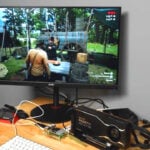
Wow, that’s great. Nice Philips CM8833 monitor too, I’ve got one of those around somewhere!
Brian Tristam Williams
Very nice! Would love to try this.
You say VGA OR RGB/SCART. Question 1: Does the system also support VGA timing? If not, then just a note: The mention of VGA here is an unintentional fuzzy red herring. VGA monitors will not run at 50 Hz (leaving aside extremely rare multisync monitors). However, as you’ve shown, a standard (non-VGA) RGB/composite monitor such as the Philips CM8833 pictured above is perfect for the task — it has RGB-in via its SCART connector at the back.
Question 2: Is it “true” 50Hz interlacing, where objects moving in a video can be seen in different places in each of the unique 50 Hz fields, or is every pair of fields (one frame) identical in the temporal domain?
Nick Hollinghurst — post author
Hi,
1. The DPI block supports VGA up to 1920x1200p60 with a VGA666 or similar HAT. Though for want of a suitable monitor, I haven’t tested it in a high-resolution interlaced VGA mode.
My fuzzy use of “VGA” really meant “thing that accepts separate syncs”. In the picture the SCART HAT is doing the sync combining.
2. Yes, unlike the VEC (composite video) peripheral, it can accept updates at 50Hz and display each one.
Jope
Does the driver also support 288P and 240P, where each field is the same parity and gets drawn on top of the scanlines of the last field?
Old games consoles and home computers had this kind of low vertical resolution progressive output.
Nick Hollinghurst — post author
Yes, those modes were supported before and are still available. Interlace is what’s been added (and, more experimentally, CSync).
Richard
” The odd lines are scanned from top to bottom, followed by the even ones. This reduces flicker”
From what I remember, interlaced increased flicker??? Or just my old brain playing ticks on me. :)
It’s cool that there are still companies happy to add support for old kit. :)
Anders
Non-interlaced displays would flicker less but require to scan the whole frame twice as fast.
Years ago I worked on CRT and non-interlaced were the expensive no-flicker options. Interlaced displays were cheaper but more flickery, the flicker could be reduced by using CRTs with high persistence phosphor.
fanoush
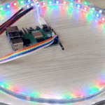
Maybe the meaning was that 50Hz interlaced flickers less than 25Hz not interlaced (as the raspberry animation shows)?
Brian Tristam Williams
Interlacing reduces flicker by allowing the scanline to get back to refreshing the top of the image twice as often as progressive scanning. If you scanned progressively at the same line frequency, you’d end up with a 25 Hz flicker that might give you a headache :-D By drawing only half of the lines per field scan, the screen can be updated at 50 Hz, reducing flicker substantionally.
Nick
Is this work related to Eben’s comments about how to make a very low cost computer (possibly running the OS of an early console/home computer) to extend learning more widely around the world?.
Nick Hollinghurst — post author
Not exactly — those goals can generally be met using Composite Video or HDMI, perhaps even with the HDMI-to-VGA converter cable.
The DPI interface provides RGB output with extremely flexible timings. Apart from its main use with actual DPI panels, it’s handy for “retro” applications that need to match the look and feel of other technologies.
Adenilson Cavalcanti
Pretty awesome stuff!
Question: would it work to output 240p (say like running a SNES emulator) to a Sony PVM that can only display up to 480i?
Nick Hollinghurst — post author
Most monitors that display 480i should display 240p. So probably it can do this already.
(If you need to “bob” the image over two fields, BBC-Micro-style: the DPI driver won’t do that right now, but you could maybe hack it to do so. It’s not an option I had considered.)
That’s assuming RGBHV input of course. If the monitor is Composite only, you’ll need the Composite output. That also has interlaced and progressive modes.
Kev
Now we just need someone to fix the dpidac bridge driver to allow for this. https://github.com/rtomasa/rpi-dpidac
Nick Hollinghurst — post author
Yes, need to add pin 1 (for the DEN “gotcha”).
In the meantime you can maybe use the generic overlay, as above. Add “rgb666-padhi” for mode 6. That will also enable pin 0, which might not suit all HATs. It will only do one video mode at a time.
Kevin
It looks like the kernel will need to be patched as interlacing is disabled by default correct?
https://github.com/raspberrypi/linux/blob/9da8d6df2051478f0ba16d73c65995955c19cb3a/drivers/gpu/drm/vc4/vc4_dpi.c#L258
https://github.com/raspberrypi/linux/issues/2668
Nick Hollinghurst — post author
That’s specific to VC4 (KMS driver for Raspberry Pi 0-4). It looks like the restriction was imposed upstream, as interlace isn’t specified for the DPI standard. We would need a strong justification to patch it downstream.
When we come to upstream the RP1 driver I’ll try to prevent it suffering the same fate.
Kevin
Well that was easy! No modification of the driver needed! Just apt full upgrade and then reinstalled the dpidac driver. Interlacing now works great and I still have the calamity resolution changes on the fly.
Thank you!
Kevin
Thank you for all the help, one question I have is that we are seeing a difference in interlacing speed between pi4 and pi5. On the Pi5 the interlacing has a significant amount of flicker compared to pi4, it’s almost like a slow interlace. Is this expected?
Nick Hollinghurst — post author
It will flicker, but it shouldn’t be very different, unless it’s some HVS scaling/overscan difference, which I can’t do much about.
Make sure you’ve edited the overlay to add GPIO 1 (or try the generic overlay again), and try the latest rpi-6.12.y kernel. If a difference can easily be demonstrated on RPiOS (e.g. using kmstest) please raise an issue on github.com/raspberrypi/linux.
Brian
How much lag would this add to the video to do this? For example the lag between a game controller and the video happening on the screen.
Nick Hollinghurst — post author
Interlace should add zero lag; it can still update at 50-60fps.
Will moindrot
Very interested in your to play 80’s movies on a CRT. Can you suggest a hat that can take advantage of this new feature whilst outputting scart? I wondered what you were using in the pics. Thanks, Will
Nick Hollinghurst — post author
The trouble with most SCART HATs is that they can’t send audio to the TV from a Raspberry Pi 5 (unless you use a SCART breakout connector and a USB audio device). Arcadeforge PI2SCART has an audio in connector, but might be hard to find. Interlace on RP1 requires GPIO1, so a modified overlay may also be needed.
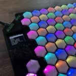
The one pictured was a Recalbox RGB Dual, but it wasn’t designed for Raspberry Pi 5. Recalbox are working on a replacement which will have onboard PCM audio DAC.
All these HATs have 18-bit RGB which isn’t ideal for movies. You might be better off with Composite Video (which will give it more of a VHS look!)
Will moindrot
Thanks Nick! Might need to dig out my 1b!
Comments are closed