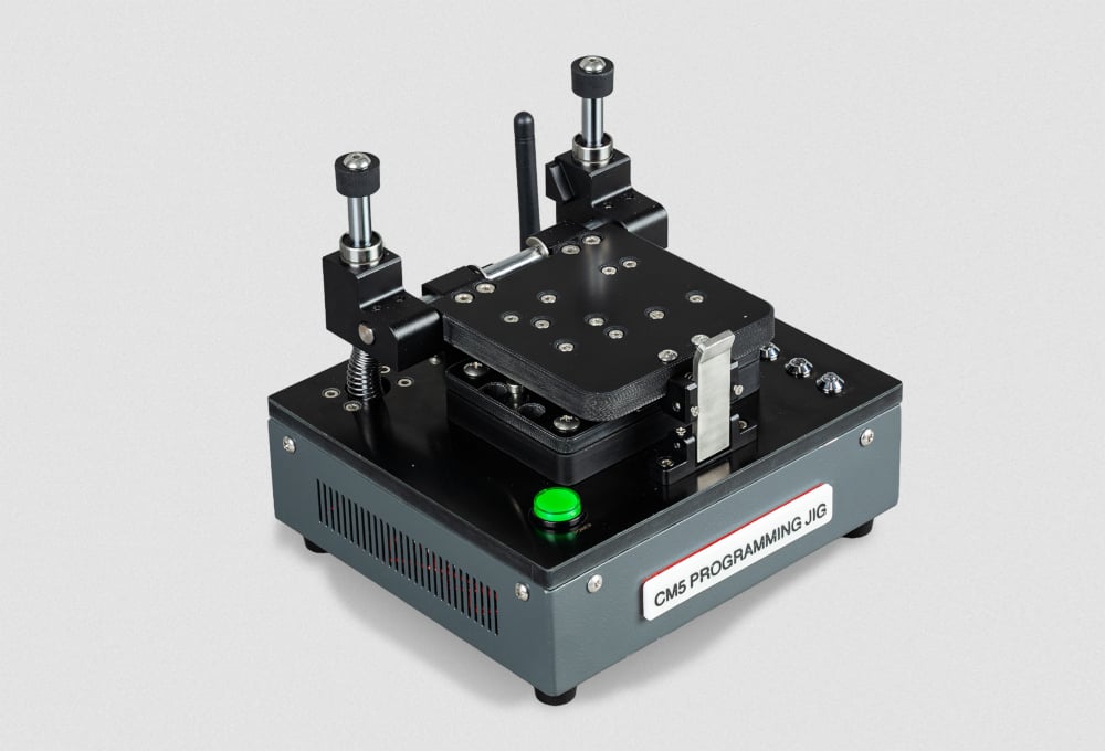
The Compute Module 5 programming jig is a single-head provisioning system designed to program Compute Module 5 devices with an operating system and security configuration. It interfaces directly with Compute Module 5, eliminating the need for a separate IO board during provisioning.
Key features
- Automated provisioning: supports secure boot, full-disk encryption, and bare operating system installation.
- Single-head design: provisions one Compute Module 5 at a time
- Mechanical clamping: secures the Compute Module 5 in place during programming
- Pogo pin interface: connects directly to Compute Module 5 without a carrier board
- LED status indicators: communicate the current state of the jig and provisioning progress
- Dual network connectivity: connects the jig to the provisioning network by Ethernet (JIG ETH) or Wi-Fi®, with a second Ethernet port (DUT ETH) for accelerated software transfer to the Compute Module 5 being programmed
- Automated provisioning with rpi-sb-provisioner: supports secure boot, full-disk encryption, and bare operating system installation
We brought Compute Module 5 programming jig to Embedded World to give you a chance to try it out. Follow the steps in the Program a Compute Module 5 with the jig section to provision a Compute Module 5 with an operating system image. Or, to learn more about the jig, skip down to the About the jig section.
Program a Compute Module 5 with the jig
The Compute Module 5 programming jig at Embedded World is already installed, configured, and ready to go. Use it to provision a Compute Module 5 with an operating system image.
Before you begin, ensure that the jig is powered on with the JIG LED showing green.
Warning: Never close and clamp the jig shut without a Compute Module 5 inside. Doing this can damage the delicate metal pogo pins.
Step 1: Load the Compute Module 5 into the jig
- Open the clamping mechanism. Press the top of the latch backwards to release it, allow the lid to slide up, then pivot the lid back until it stops.
- Place the Compute Module 5 into the module bay, aligning the holes on the corners of the Compute Module 5 with the through-hole studs on the corners of the module recess. The studs thread through the holes on the Compute Module 5. Ensure that the Raspberry Pi logo on the Compute Module 5 has the same orientation as the logo on the jig.
- Close the clamping mechanism. Pivot the lid forwards until it is parallel with the Compute Module 5 and press the lid so it slides down. When it reaches the bottom, the latch engages and secures the Compute Module 5 in place.
Warning: Ensure the through-hole studs pass through all four corner holes on the Compute Module 5 before closing the clamp. Incorrect alignment can result in a failed provisioning attempt or damage to the pogo pins.
Step 2: Monitor provisioning progress
After the Compute Module 5 is clamped in place, the jig begins provisioning automatically. Don’t remove the Compute Module 5 before provisioning is complete.
Monitor the Status LED on the jig to track progress through the provisioning phases:
During the bootstrap and triage phase, the Status LED is orange. The jig recognises the Compute Module 5 and loads a temporary Linux environment. For secure-boot mode, the signing key hash is programmed into the device OTP memory (this is a permanent operation).The jig determines the appropriate provisioning service based on the selected security mode.
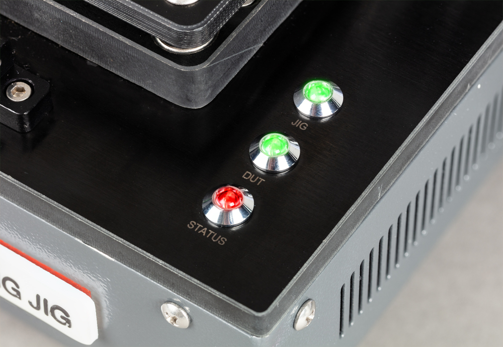
During the provisioning phase, the Status LED is red. The jig creates encryption keys (if applicable), formats storage, and installs the operating system.
IMAGE TODO all green LEDs
When the Status LED turns green, provisioning is complete. You can now remove it from the jig.
Step 3: Remove the Compute Module 5
To remove the Compute Module 5 from the jig:
- Open the clamping mechanism. Press the top of the latch backwards to release it, allow the lid to slide up, then pivot the lid back until it stops.
- Remove the Compute Module 5 from the module bay.
The Compute Module 5 is ready for deployment.
Note: Typical provisioning time is approximately 1.5 minutes per device for a 2.6 GB operating system image installed in naked provisioning mode. Actual time varies depending on image size, storage type, and network speed.
About the jig
Front panel
This view shows the label of the product and the latch that holds the clamp shut.
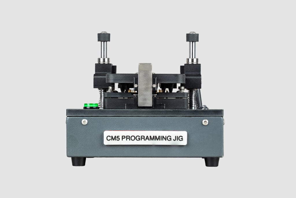
Rear panel
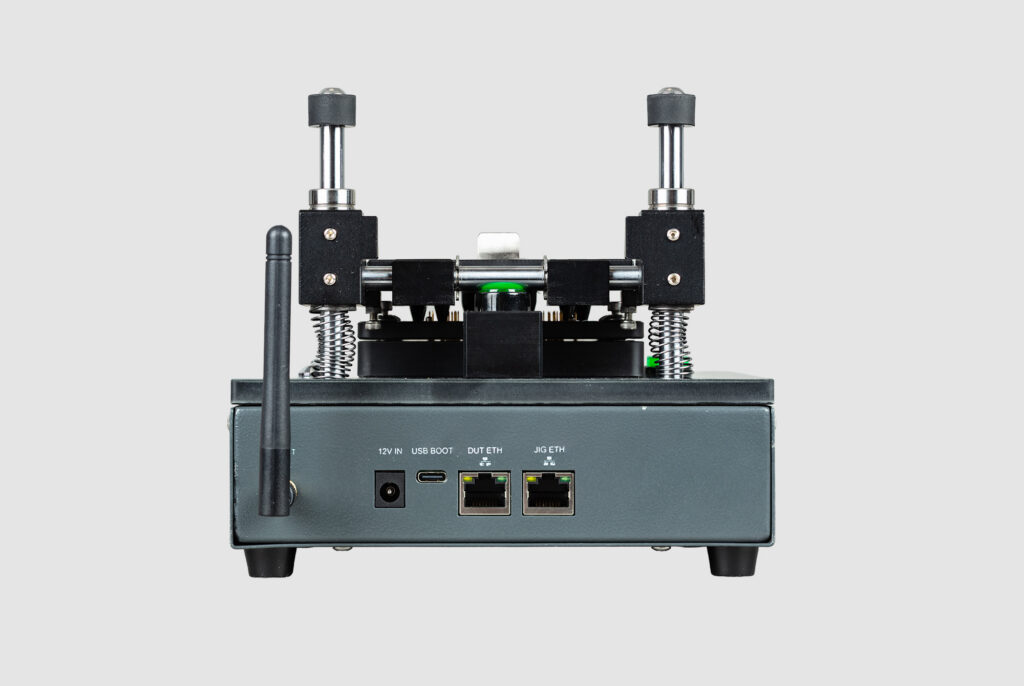
This view shows the Wi-Fi antenna and the following input ports: 12 V power supply, USB-C, DUT Ethernet, and JIG Ethernet.
Module bay
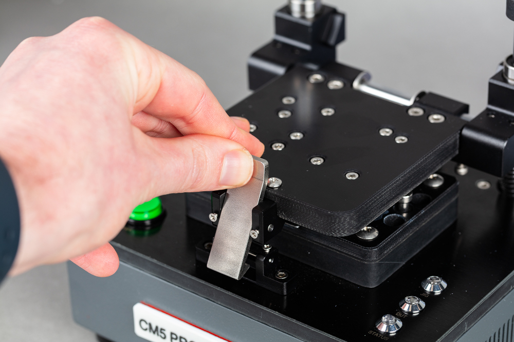
This view shows the metal latch at the front of the jig. This latch holds the module bay closed.
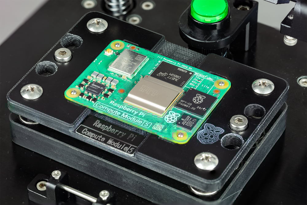
This view shows the module bay with a Compute Module 5 board seated in it.
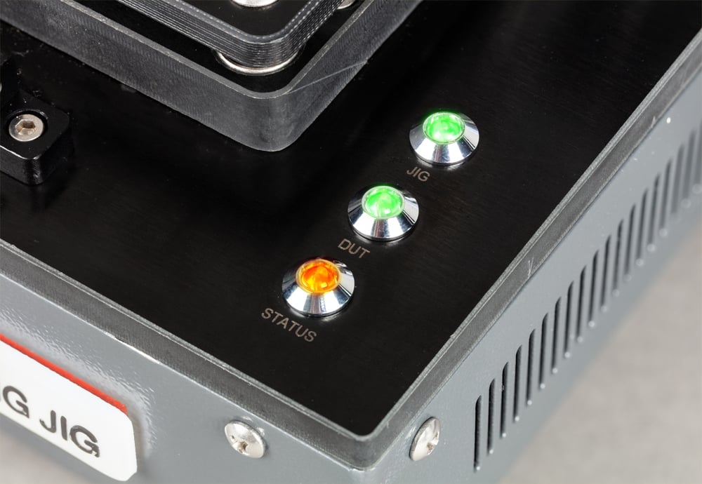
LED indicators
The jig uses LED indicators to communicate its current state. The following table describes each LED and its meaning.
There are three LED indicators on the top of the jig: JIG, DUT, and STATUS.
| LED | State | Meaning |
|---|---|---|
| JIG | Off | The jig is not powered. |
| JIG | Green | The jig is online. |
| JIG | Flashing green | The jig is active (data transfer in progress). |
| JIG | Red | The jig is offline. Press the POWER button to bring the jig online. |
| DUT | Off | The jig is not powered, or no Compute Module 5 is present. |
| DUT | Green | The Compute Module 5 is online. |
| DUT | Flashing green | The Compute Module 5 is active (data transfer in progress). |
| DUT | Red | The Compute Module 5 is offline. This can indicate that the Compute Module 5 is damaged. If this light remains red with multiple different modules, this can indicate a problem with the jig; contact us for support. For more information, see Getting help. |
| STATUS | Off | No provisioning operation in progress. |
| STATUS | Orange | Bootstrap and triage phases. The jig is recognising the Compute Module 5 and preparing the provisioning service. Don’t remove the Compute Module 5 during this phase. |
| STATUS | Red | Provisioning phase. The jig is writing the operating system and configuring security. Don’t remove the Compute Module 5 during this phase. |
| STATUS | Green | Provisioning is complete. The Compute Module 5 can be removed. |
Buttons
There are two buttons on the top of the jig:
| Button | Description |
|---|---|
| POWER | Controls the power state of the jig. Press to turn the jig on or off. |
| Unmarked | Safety switch for the provisioning software. Don’t manually press this button; it is activated by the closing of the lid. |
Warning: Don’t press the unmarked button. It is used internally by the provisioning software. Manually actuating this button can interrupt a provisioning operation.
Connectors and interfaces
There are four external connectors on the jig:
| Connector | Description |
|---|---|
| 12 V power | 12 V 2 A (24 W) DC input for use with the supplied power supply. |
| USB Boot | USB-C port for programming the jig itself. Connect this port to your computer when using rpiboot to write the jig’s operating system (see Step 1: Write the operating system to the jig). |
| JIG ETH | Ethernet interface for the programming jig. Connects the jig to the provisioning network for configuration, management, and software updates. |
| DUT ETH | Ethernet interface for the Compute Module 5 device being programmed. Connect this port to the provisioning network for accelerated data transfer to the Compute Module 5 during provisioning. |
The jig also supports Wi-Fi for connecting to the provisioning network wirelessly, as an alternative to the JIG ETH port.
Safety information
- Disconnect the jig from the power supply before performing any maintenance.
- Don’t touch the metallic pogo pins in the module bay. They are sharp and can carry charge; you might damage the pins, the jig, or yourself.
- Don’t close and clamp the lid without a Compute Module 5 in the module bay; this can damage the pogo pins.
- Ensure that the Compute Module 5 is correctly seated in the module bay, with the Raspberry Pi logo facing up and oriented in the same direction as the logo on the jig. Seating it incorrectly can damage the pogo pins.
- Don’t remove the Compute Module 5 from the jig while the bootstrap and triage (STATUS LED is orange) or provisioning (STATUS LED is orange) process is in progress; this can render the Compute Module 5 unusable.
- Don’t press the unmarked button on the jig; this can interrupt provisioning and render the Compute Module 5 unusable.
Specifications
| Compatible devices | Compute Module 5 |
| Provisioning heads | 1 |
| JIG ETH | Ethernet (10/100/1000) or Wi-Fi (2.4 GHz and 5.0 GHz IEEE 802.11 b/g/n/ac). |
| DUT ETH | Ethernet (10/100/1000) |
| USB Boot | USB-C |
| Power input | 12 V 2 A (24 W) DC |
| Dimensions | 172 × 188 × 154 mm |
| Weight | 1796 g |