$ ssh <username>@pi-cluster.local

<username>@pi-cluster.local's password:
$note
Now updated for Raspberry Pi OS Bookworm.
Why would you build a physical cluster? Today you can go to Amazon, or Digital Ocean, or any of the other cloud providers, and spin up a virtual machine in seconds. But the cloud is just someone else’s computers: a Raspberry Pi cluster is a low-cost, versatile system you can use for all kinds of clustered-computing related technologies, and you have total control over the machines that constitute it. Building something from the ground up can teach you lessons you can’t learn elsewhere.
What we’re going to build

We’re going to put together an eight-node cluster connected to a single managed switch. One of the nodes will be the so-called "head" node: this node will have a second Gigabit Ethernet connection out to the LAN/WAN via a USB3 Ethernet dongle, and an external 1TB SSD mounted via a USB3-to-SATA connector. While the head node will boot from an SD card as normal, the other seven nodes — the "compute" nodes — will be configured to network boot, with the head node acting as the boot server and the OS images being stored on the external disk. As well as serving as the network boot volume, the 1TB disk will also host a scratch partition that is shared to all the compute nodes in the cluster. All eight of our Raspberry Pi boards will have a Raspberry Pi PoE+ HAT attached. This means that, since we’re using a PoE+ enabled switch, we only need to run a single Ethernet cable to each of our nodes and don’t need a separate USB hub to power them.
What you’ll need
Supplies
-
8 x Raspberry Pi 4
-
8 x Raspberry Pi PoE+ HAT
-
8-port Gigabit PoE-enabled switch
-
USB 3 to Gigabit Ethernet adaptor
-
USB 3 to SATA adaptor
-
SSD SATA drive
-
8 x Ethernet cables
-
16 GB SD card
-
Cluster case
The list of parts you’ll need to put together a Raspberry Pi cluster — sometimes known as a "bramble" — can be short, or it can be quite long, depending on what size and type of cluster you intend to build. So it’s important to think about what you want the cluster to do before you start ordering the parts to put it together. The list above is what we used for our eight-Pi cluster, but your requirements might well be different.
What you will need is a full bramble of Raspberry Pi computers, and if you’re intending to power them over PoE as we are, you’ll need a corresponding number of Raspberry Pi PoE+ HAT boards and an appropriate PoE+ switch. Beyond that, however, you’ll need a micro SD card, some Ethernet cables, a USB to Ethernet adapter, a USB to SATA adapter cable along with an appropriately sized SSD drive, and some sort of case to put all the components into after you’ve bought them. The case can either be a custom-designed "cluster case" or, perhaps, something rack-mountable depending on what you’re thinking of doing with the cluster after you’ve built it.
There is however a lot of leeway in choosing your components, depending on exactly what you’re setting up your cluster to do. For instance, depending on the sorts of jobs you’re anticipating running across the cluster, you might be able to get away with using cheaper 2GB or 1GB boards rather than the 4GB model I used. Alternatively, having a local disk present on each node might be important, so you might need to think about attaching a disk to each board to provide local storage.
However, perhaps the biggest choice when you’re thinking about building a cluster is how you’re going to power the nodes. We used PoE for this cluster, which involved adding a PoE+ HAT board to each node and purchasing a more expensive switch capable of powering our Raspberry Pi boards: for larger clusters, this is probably the best approach. For smaller clusters, you could instead think about powering the nodes from a USB hub, or for the smallest clusters — perhaps four nodes or fewer — powering each node directly from an individual power supply.
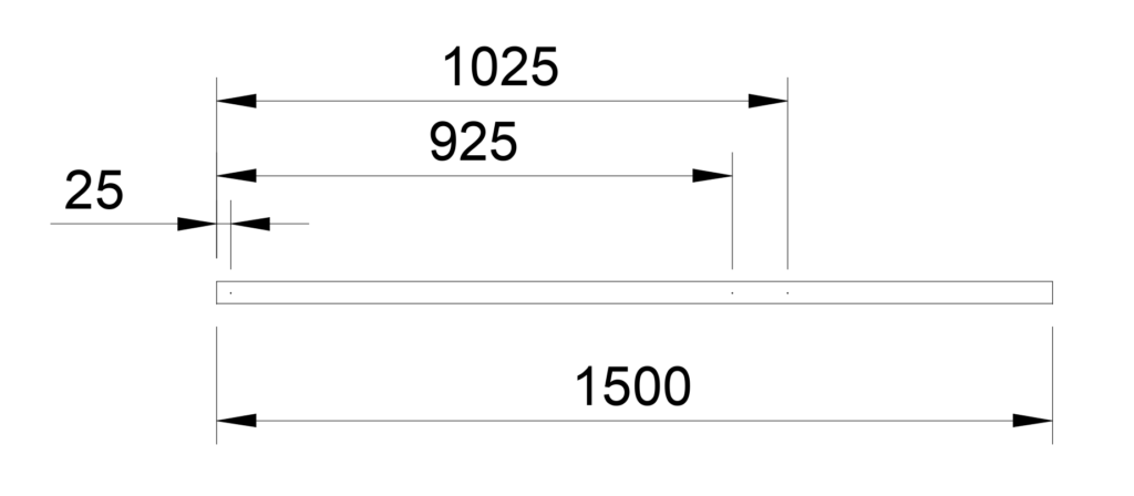
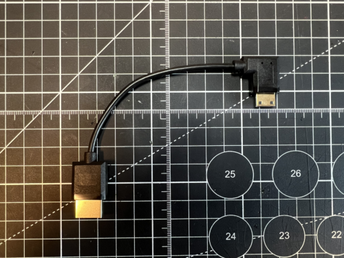
Make your own USB fans
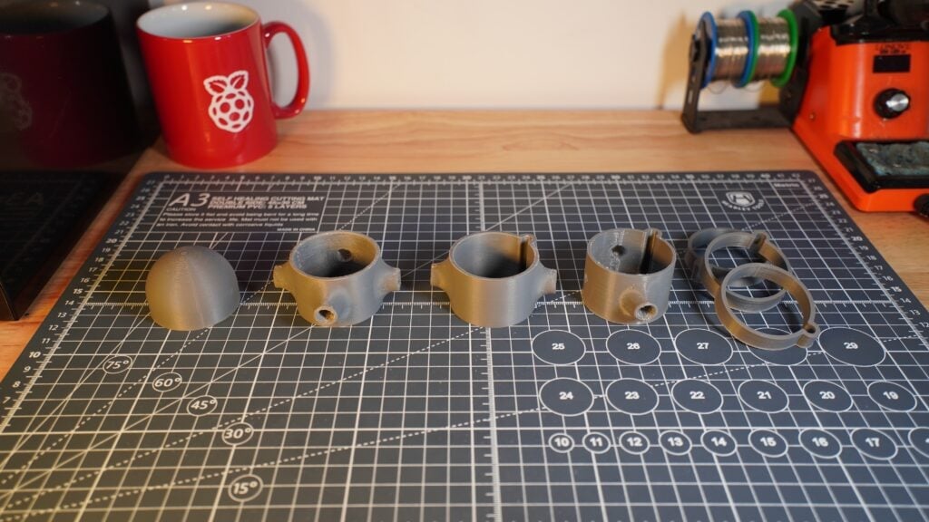
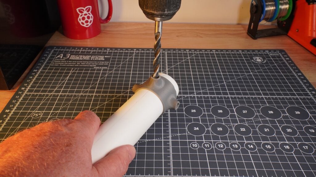
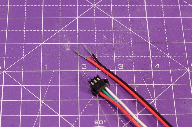
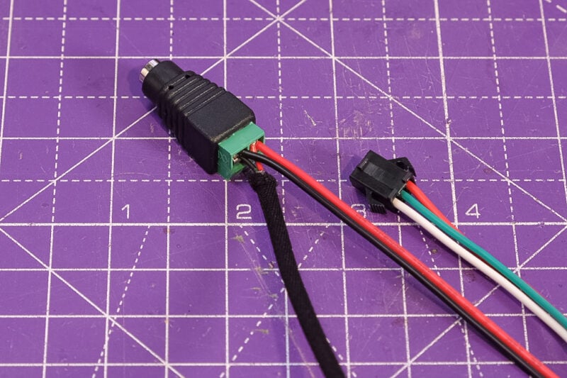
If you decide to power your cluster using PoE, you’ll find you may have to make up some franken-cables. For instance, the fans at the back of the case I’m using were intended to connect to the GPIO header block on the Raspberry Pi, but since we’re using the Raspberry Pi PoE+ HAT to power our nodes, we don’t have access to the GPIO headers.
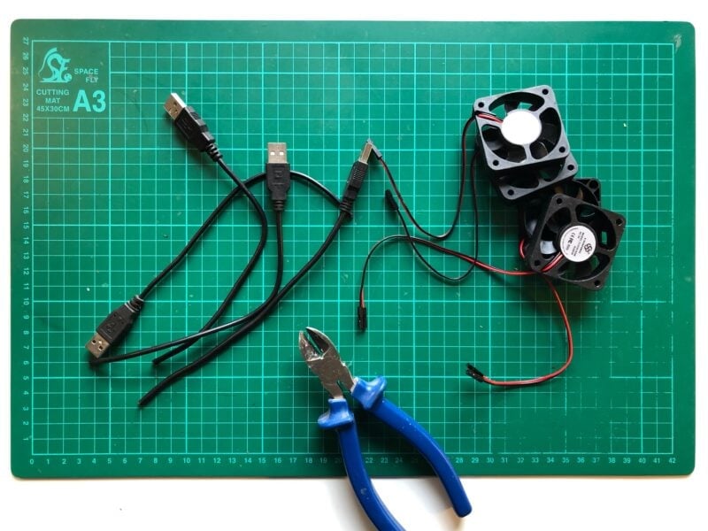
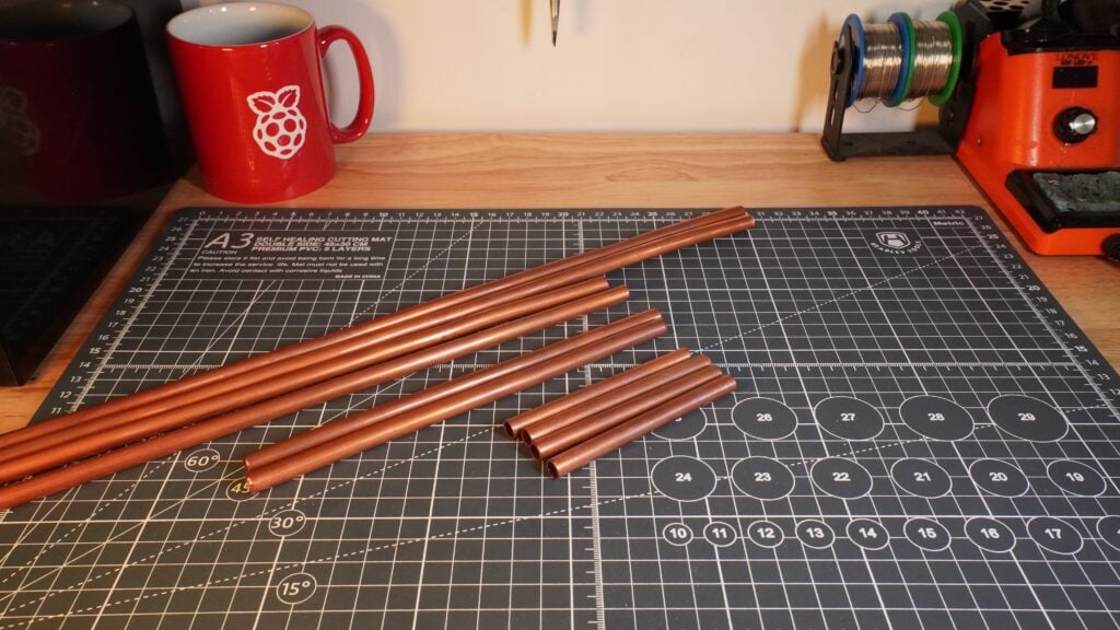
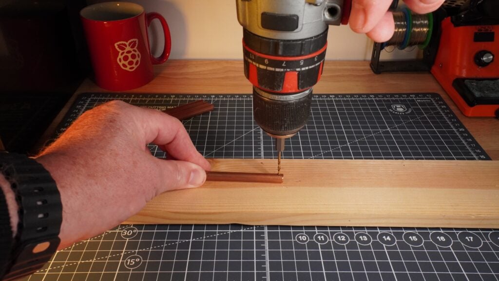
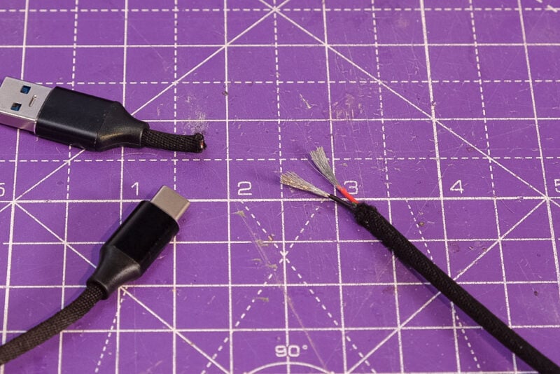
Therefore, for me at least, it’s time to grab some donor USB cables and make up some cables. If you snip the end from a USB cable and peel back the plastic you’ll find four wires; these will often be inside an insulating metal sheath. The wires inside the cable are small and delicate, so carefully strip back the cover if present. You’re looking for the red (+5V) and black (GND) wires. The other two, normally coloured white and green, carry data. You can just cut these data wires off; you won’t need them.

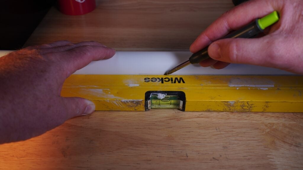
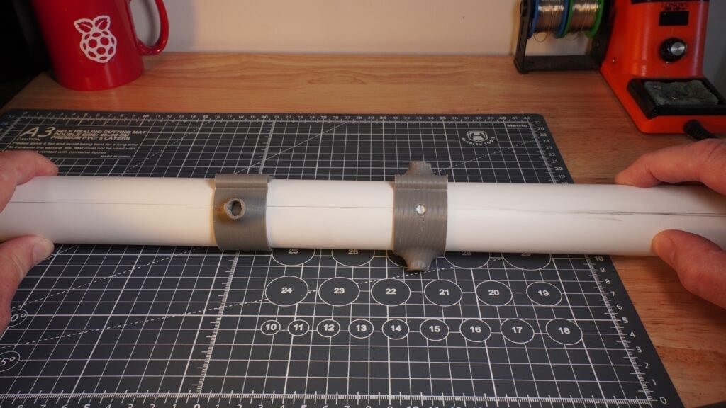
Solder the red and black wires from the fan to the red and black wires in the USB cable. The best thing to do here is to use a bit of heat-shrink tubing over each of the individual solder connections, and then use a bigger bit of heat-shrink over both of the soldered connectors. This will give an electrically insulated, and mechanically secure, connection between the fan and the USB plug end of the new cable.
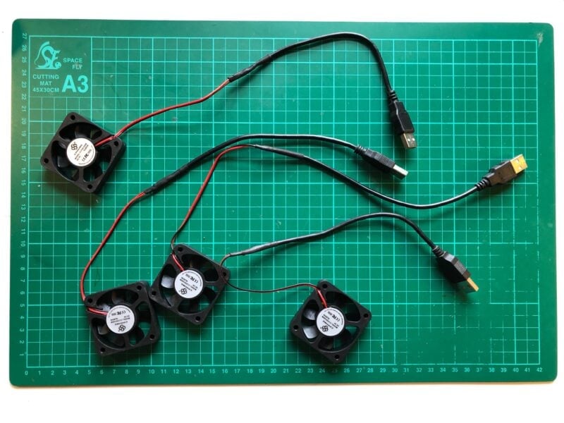
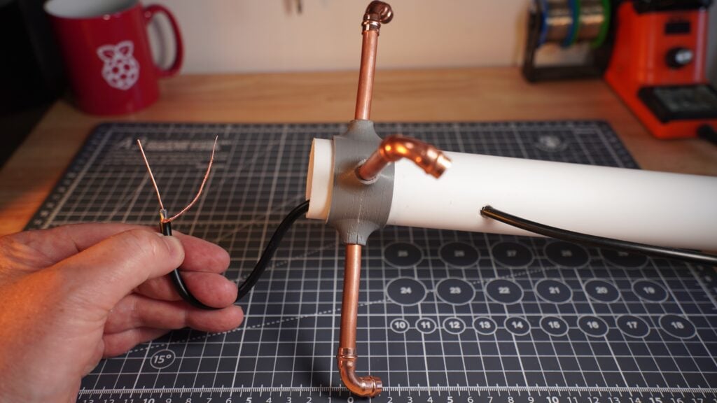
The cluster case I’m using has four fans, mounted at the rear. I’m going to be powering the left-hand two from the head node, or potentially from the first compute node on the left if I need more USB sockets on the head node, and the right-hand two from the right-most compute node.

The most common case where you’ll need Franken-cables is probably this one — powering a fan over USB due to lack of access to the GPIO header. But there are other reasons you might need them. For instance, for a cluster I built a few years back, I needed to put together a cable to power an Ethernet switch from a USB hub, rather than from +5V power supply unit.
Configure your Raspberry Pi
To begin, follow the Getting Started documentation to set up your Raspberry Pi. For your operating system, choose Raspberry Pi OS (other) > Raspberry Pi OS Lite to run headless (without a mouse and keyboard).
During the OS customisation stage, edit settings as follows:
-
Enter a hostname of your choice (we suggest
pi-clusterfor this tutorial) -
Enter a username (we suggest pi for this tutorial) and password; you’ll need these later to authenticate
-
Check the box next to Configure wireless LAN so your Pi can automatically connect to Wi-Fi
-
Enter your network SSID (name) and password; you can find these in your Wi-Fi settings or on a sticker on your router
-
Check the box next to Enable SSH so we can connect to the Pi without a mouse and keyboard
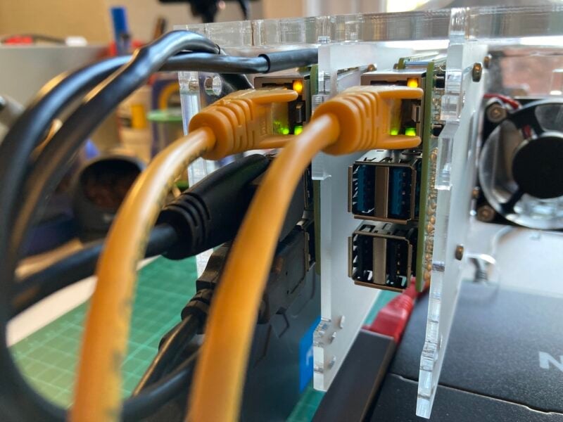
Building your head node

The exact way you plug things together is going to depend on your cluster components and whether you picked up a case, or more likely what sort of case you have. I’m going to slot my head node into the far left-hand side of my case. This lets me mount the SSD drive against one wall of the case using a mounting screw to secure it in place.

Connect over wireless
We configured the head node to know about our local wireless network during setup, so we should just be able to ssh directly into the head node using the name we gave it during setup:
If we take a look at the network configuration by typing nmcli,
$ nmcli
wlan0: connected to preconfigured
        "Broadcom BCM43438 combo and Bluetooth Low Energy"
        wifi (brcmfmac), DC:A6:32:6A:16:91, hw, mtu 1500
        inet4 10.3.194.40/22
        route4 10.3.192.0/22 metric 600
        route4 default via 10.3.194.1 metric 600
        inet6 2001:4d4e:300:c2:1fd1:9c44:f362:3805/64
        inet6 fe80::a725:b6cc:ce19:3caf/64
        route6 fe80::/64 metric 1024
        route6 2001:4d4e:300:c2::/64 metric 600
        route6 default via fe80::dccc:45ff:fe78:a3cc metric 600

lo: connected (externally) to lo
        "lo"
        loopback (unknown), 00:00:00:00:00:00, sw, mtu 65536
        inet4 127.0.0.1/8
        inet6 ::1/128

eth0: disconnected
        "eth0"
        1 connection available
        ethernet (bcmgenet), DC:A6:32:6A:16:90, hw, mtu 1500

DNS configuration:
        servers: 10.3.31.1
        domains: pitowers.org
        interface: eth1

        servers: fe80::8498:d3ff:fe31:8eac
        interface: eth1

        servers: 10.3.194.1
        domains: pitowers.org
        interface: wlan0

        servers: fe80::dccc:45ff:fe78:a3cc
        interface: wlan0

$
you can see that wlan0 is connected to our local network with a 10.3.\* address, while eth0 which we’ve plugged into our switch is disconnected. We’ll resolve this later in the project by turning our head node into a DHCP server that will assign an IP address to each of the compute nodes, as well as to our smart switch.
Add a second Ethernet connection
We’ve been able to reach our head node over the network because we configured our wireless interface wlan0 when we set up our SD card. However, it would be good to hardwire our cluster to the network rather than rely on wireless, because we might want to transfer large files back and forth, and wired interfaces are a lot more stable.
To do that we’re going to need an additional Ethernet connection, so I’m going to add a USB 3-to-Gigabit Ethernet adaptor to the head node. We’ll leave the onboard Ethernet socket (eth0) connected to our PoE switch to serve as the internal connection to the cluster, while we use the second Ethernet connection (eth1) to talk to the outside world.
In most cases eth1 will be activated automatically by Network Manager, and pick up an IP address from our LAN’s DHCP server. After plugging in our adaptor we should see something like this,
eth1: connected to Wired connection 2
        "Realtek RTL8153"
        ethernet (r8152), 00:E0:4C:68:1D:DA, hw, mtu 1500
        ip4 default, ip6 default
        inet4 10.3.31.194/24
        route4 10.3.31.0/24 metric 100
        route4 default via 10.3.31.1 metric 100
        inet6 2001:4d4e:300:1f:6f2a:f4b1:65a8:b420/64
        inet6 fe80::7a88:6d47:4554:bd80/64
        route6 fe80::/64 metric 1024
        route6 2001:4d4e:300:1f::/64 metric 100
        route6 default via fe80::8498:d3ff:fe31:8eac metric 100
added to the results of typing nmcli on the command line.
We’ll leave eth0, the onboard Ethernet socket, connected to the Ethernet switch to serve as the internal connection to the cluster. Internally we’ll allocate 192.168.50.*/24 addresses to the cluster, with our head node having the IP address 192.168.50.1.
$ sudo nmcli con mod "Wired connection 1" ipv4.addresses 192.168.50.1/24 ipv4.method manual
$ sudo nmcli con down "Wired connection 1"
$ sudo nmcli con up "Wired connection 1"
Then, if everything has gone to plan, you should see something like this:
$ nmcli
eth1: connected to Wired connection 2
        "Realtek RTL8153"
        ethernet (r8152), 00:E0:4C:68:1D:DA, hw, mtu 1500
        ip4 default, ip6 default
        inet4 10.3.31.194/24
        route4 10.3.31.0/24 metric 100
        route4 default via 10.3.31.1 metric 100
        inet6 2001:4d4e:300:1f:6f2a:f4b1:65a8:b420/64
        inet6 fe80::7a88:6d47:4554:bd80/64
        route6 fe80::/64 metric 1024
        route6 2001:4d4e:300:1f::/64 metric 100
        route6 default via fe80::8498:d3ff:fe31:8eac metric 100

wlan0: connected to preconfigured
        "Broadcom BCM43438 combo and Bluetooth Low Energy"
        wifi (brcmfmac), DC:A6:32:6A:16:91, hw, mtu 1500
        inet4 10.3.194.40/22
        route4 10.3.192.0/22 metric 600
        route4 default via 10.3.194.1 metric 600
        inet6 2001:4d4e:300:c2:1fd1:9c44:f362:3805/64
        inet6 fe80::a725:b6cc:ce19:3caf/64
        route6 fe80::/64 metric 1024
        route6 2001:4d4e:300:c2::/64 metric 600
        route6 default via fe80::dccc:45ff:fe78:a3cc metric 600

eth0: connected to Wired connection 1
        "eth0"
        ethernet (bcmgenet), DC:A6:32:6A:16:90, hw, mtu 1500
        inet4 192.168.50.1/24
        route4 192.168.50.0/24 metric 101
        inet6 fe80::a5a8:6819:ddc6:6b2f/64
        route6 fe80::/64 metric 1024

lo: connected (externally) to lo
        "lo"
        loopback (unknown), 00:00:00:00:00:00, sw, mtu 65536
        inet4 127.0.0.1/8
        inet6 ::1/128

DNS configuration:
        servers: 10.3.31.1
        domains: pitowers.org
        interface: eth1

        servers: fe80::8498:d3ff:fe31:8eac
        interface: eth1

        servers: 10.3.194.1
        domains: pitowers.org
        interface: wlan0

        servers: fe80::dccc:45ff:fe78:a3cc
        interface: wlan0

$
Configure the DHCP server
Now we have a "second" Gigabit Ethernet connection out to the world via eth1, and our onboard Ethernet is configured with a static IP address, it’s time to make our Raspberry Pi into a DHCP server for our cluster on eth0.
Start by installing the DHCP server itself:
$ sudo apt install isc-dhcp-serverand then edit the /etc/dhcp/dhcpd.conf file as follows:
ddns-update-style none;
authoritative;
log-facility local7;

# No service will be given on this subnet
subnet 10.3.31.0 netmask 255.255.255.0 {
}

# The internal cluster network
group {
   option broadcast-address 192.168.50.255;
   option routers 192.168.50.1;
   default-lease-time 600;
   max-lease-time 7200;
   option domain-name "cluster";
   option domain-name-servers 8.8.8.8, 8.8.4.4;
   subnet 192.168.50.0 netmask 255.255.255.0 {
      range 192.168.50.20 192.168.50.250;

      # Head Node
      host cluster {
         hardware ethernet dc:a6:32:6a:16:90;
         fixed-address 192.168.50.1;
      }

   }
}
Then edit the /etc/default/isc-dhcp-server file to reflect our new server setup:
DHCPDv4_CONF=/etc/dhcp/dhcpd.conf
DHCPDv4_PID=/var/run/dhcpd.pid
INTERFACESv4="eth0"
as well as the /etc/hosts file:
127.0.0.1	localhost
::1		localhost ip6-localhost ip6-loopback
ff02::1		ip6-allnodes
ff02::2		ip6-allrouters

127.0.1.1	cluster

192.168.50.1	cluster
and then you can reboot the head node to start the DHCP service.
We’ve set things up so that known hosts that aren’t known are allocated an IP address starting from 192.168.50.20. Once we know the MAC addresses of our compute nodes we can add them to the /etc/dhcp/dhcpd.conf file so they grab static IP addresses going forward rather than getting a random one as they come up.
Logging back into your head node after the reboot if you have a managed switch for your cluster, like the NETGEAR switch I’m using which will grab an IP address of its own, you can check your DHCP service is working:
$ dhcp-lease-list
Reading leases from /var/lib/dhcp/dhcpd.leases
MAC                IP              hostname       valid until         manufacturer
==================================================================================
80:cc:9c:94:53:35  192.168.50.20   GS308EPP       2021-12-06 14:19:52 NETGEAR
$
Otherwise, you’ll have to wait until you add your first node as unmanaged switches won’t request their own address.
However, if you do have a managed switch, you might well want to give it a static IP address inside the cluster by adding one to the /etc/dhcp/dhcpd.conf and /etc/hosts files in a similar fashion to the head node. I went with switch as the hostname:
192.168.50.1	cluster
192.168.50.254	switch
and 192.168.50.254 as the allocated IP address:
subnet 192.168.50.0 netmask 255.255.255.0 {
range 192.168.50.20 192.168.50.250;
# Head Node
host cluster {
hardware ethernet dc:a6:32:6a:16:90;
fixed-address 192.168.50.1;
}
# NETGEAR Switch
host switch {
hardware ethernet 80:cc:9c:94:53:35;
fixed-address 192.168.50.254;
}
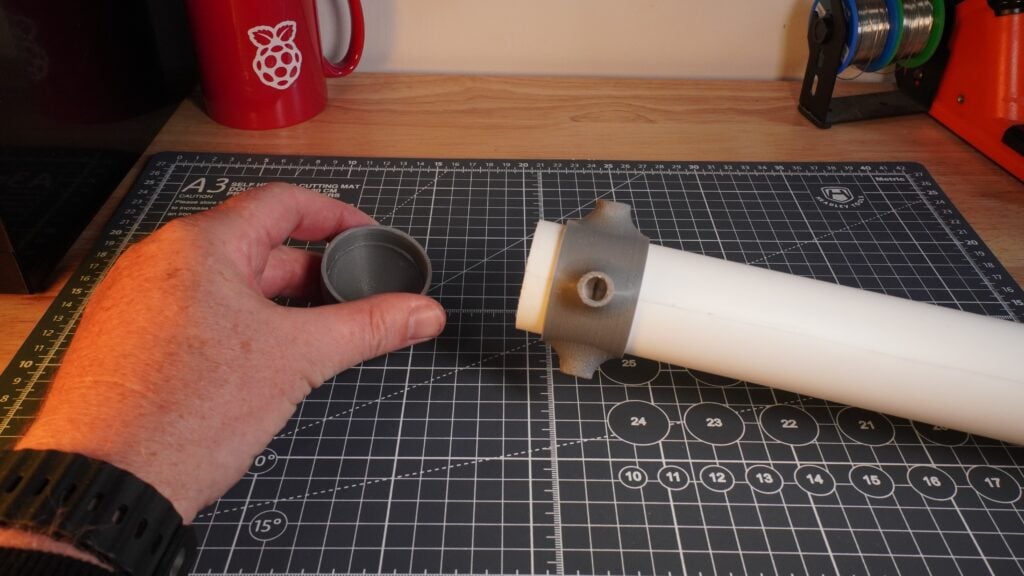
}Add an external disk
To network boot our compute nodes, we’re going to need a bit more space. You could do this by plugging a flash stick into one of the USB ports on the head node, but I’m going to use a USB 3 to SATA Adaptor Cable to attach a 1TB SSD that I had on the shelf in the lab to give the cluster plenty of space for data.
Plugging the disk into one of the USB 3 sockets on the head node I’m going to format it with a GUID partition table, and a creat single ext4 partition on the disk.
$ sudo parted -s /dev/sda mklabel gpt
$ sudo parted --a optimal /dev/sda mkpart primary ext4 0% 100%
$ sudo mkfs -t ext4 /dev/sda1
mke2fs 1.46.2 (28-Feb-2021)
Creating filesystem with 244175218 4k blocks and 61046784 inodes
Filesystem UUID: 1a312035-ffdb-4c2b-9149-c975461de8f2
Superblock backups stored on blocks:
	32768, 98304, 163840, 229376, 294912, 819200, 884736, 1605632, 2654208,
	4096000, 7962624, 11239424, 20480000, 23887872, 71663616, 78675968,
	102400000, 214990848

Allocating group tables: done
Writing inode tables: done
Creating journal (262144 blocks): done
Writing superblocks and filesystem accounting information: done
$
We can then mount the disk manually to check everything is okay:
$ sudo mkdir /mnt/usb
$ sudo mount /dev/sda1 /mnt/usb
$ sudo systemctl daemon-reload
and then make sure it will automatically mount on boot by adding the following to the /etc/fstab file:
/dev/sda1 /mnt/usb auto defaults,user 0 1You should ensure that you can mount the disk manually before rebooting, as adding it as an entry in the /etc/fstab file might cause the Raspberry Pi to hang during boot if the disk isn’t available.
Make the disk available to the cluster
We’re going to want to make the disk available across the cluster. You’ll need to install the NFS server software:
$ sudo apt install nfs-kernel-serverCreate a mount point which we can share:
$ sudo mkdir /mnt/usb/scratch
$ sudo chown pi:pi /mnt/usb/scratch
$ sudo ln -s /mnt/usb/scratch /scratch
Then, edit the /etc/exports file to add a list of IP addresses from which you want to be able to mount your disk:
/mnt/usb/scratch 192.168.50.0/24(rw,sync)Here we’re exporting it to 192.168.50.0/24 which is shorthand for "all the IP addresses between 192.168.50.0 and `192.168.50.254`".
After doing this you should enable, and then start, both the rpcbind and nfs-server services:
$ sudo systemctl enable rpcbind.service
$ sudo systemctl start rpcbind.service
$ sudo systemctl enable nfs-server.service
$ sudo systemctl start nfs-server.service
Finally, reboot:
$ sudo rebootAdd the first node
We’re going to set up our compute node to network boot from our head node. To do that we’re first going to have to configure our nodes for network boot. How to do this differs between Raspberry Pi models. However, for Raspberry Pi 4 the board must boot a single time from an SD card and the boot order configured using the raspi-config command-line tool.
Enable network boot
The easiest way to proceed is to use the Raspberry Pi Imager software to burn a second SD card with Raspberry Pi OS Lite (64-bit). There isn’t any need to specially configure this installation before booting the board as we did for the head node, except to enable SSH.
note
You should not configure or enable the wireless LAN.
Next, boot the board attached to the cluster switch:
The board should come up and be visible on the cluster subnet after it gets given an IP address by the head node’s DHCP server, and we can look at the cluster network from the head node using dhcp-lease-list:
$ dhcp-lease-list
Reading leases from /var/lib/dhcp/dhcpd.leases
MAC                IP              hostname       valid until         manufacturer
===============================================================================================
dc:a6:32:6a:16:87  192.168.50.21   raspberrypi    2021-12-07 11:54:29 Raspberry Pi Ltd
$
We can now go ahead and SSH into the new board and enable network booting using raspi-config from the command line:
$ ssh pi@192.168.50.21
$ sudo raspi-config
Choose Advanced Options > Boot Order > Network Boot. You’ll then need to reboot the device for the change to the boot order to be programmed into the bootloader EEPROM.
If you get an error when trying to enable network boot complaining that "No EEPROM bin file found" then you need to update the firmware on your Raspberry Pi before proceeding. Run the following commands:
$ sudo apt install rpi-eeprom
$ sudo rpi-eeprom-update -d -a
$ sudo reboot
Then, after the node comes back up from its reboot, try to set up network boot once again.
Once the Raspberry Pi has rebooted, check that the boot order using vcgencmd:
$ vcgencmd bootloader_config
BOOT_UART=0
WAKE_ON_GPIO=1
POWER_OFF_ON_HALT=0


[all]
BOOT_ORDER=0xf21
$
You should now see that BOOT_ORDER is 0xf21 which indicates that the Raspberry Pi will try to boot from an SD card first followed by the network. Before proceeding any further, we need to take a note of both the Ethernet MAC address and serial number of the Raspberry Pi.
$ ethtool -P eth0
Permanent address: dc:a6:32:6a:16:87
$ grep Serial /proc/cpuinfo | cut -d ' ' -f 2 | cut -c 9-16
6a5ef8b0
$
Afterwards, you can shut down the board, at least for now, and remove the SD card.
Set up the head node as a boot server
We now need to configure our head node to act as a boot server. There are several options here, but we’re going to use our existing DHCP server, along with a standalone TFTP server. You should create a mount point for the server, and install it:
$ sudo apt install tftpd-hpa
$ sudo apt install kpartx
$ sudo mkdir /mnt/usb/tftpboot
$ sudo chown tftp:tftp /mnt/usb/tftpboot
Edit the /etc/default/tftpd-hpa file:
TFTP_USERNAME="tftp"
TFTP_DIRECTORY="/mnt/usb/tftpboot"
TFTP_ADDRESS=":69"
TFTP_OPTIONS="--secure --create"
Then, restart the service:
$ sudo systemctl restart tftpd-hpaWe then need to set up our boot image, and we’re going to need to create one image per client. The first step is to grab the latest image from the web and mount it so we can make some changes, and then mount the partitions inside the image so we can copy the contents to our external disk:
$ sudo su
# mkdir /tmp/image
# cd /tmp/image
# wget -O raspios_lite_latest.img.xz https://downloads.raspberrypi.com/raspios_lite_arm64_latest
# xz -d raspios_lite_latest.img.xz
# kpartx -a -v *.img
# mkdir bootmnt
# mkdir rootmnt
# mount /dev/mapper/loop0p1 bootmnt/
# mount /dev/mapper/loop0p2 rootmnt/
# mkdir -p /mnt/usb/rpi1
# mkdir -p /mnt/usb/tftpboot/6a5ef8b0
# cp -a rootmnt/* /mnt/usb/rpi1
# cp -a bootmnt/* /mnt/usb/rpi1/boot/firmware
Where "6a5ef8b0" is the serial number of your first node which we retrieved earlier.
Afterwards, we can customise the root file system:
# touch /mnt/usb/rpi1/boot/firmware/ssh
# echo pi:$(echo 'raspberry' | openssl passwd -6 -stdin) > /mnt/usb/rpi1/boot/firmware/userconf.txt
# sed -i /UUID/d /mnt/usb/rpi1/etc/fstab
# echo "192.168.50.1:/mnt/usb/tftpboot/6a5ef8b0 /boot/firmware nfs defaults,vers=3 0 0" >> /mnt/usb/rpi1/etc/fstab
# echo "console=serial0,115200 console=tty root=/dev/nfs nfsroot=192.168.50.1:/mnt/usb/rpi1,vers=3 rw ip=dhcp rootwait" > /mnt/usb/rpi1/boot/firmware/cmdline.txt
and then add it to the /etc/exports files on the head node:
# echo "/mnt/usb/rpi1 192.168.50.0/24(rw,sync,no_subtree_check,no_root_squash)" >> /etc/exportsAnd then clean up after ourselves:
# systemctl restart rpcbind
# systemctl restart nfs-server
# umount bootmnt/
# umount rootmnt/
# cd /tmp; rm -rf image
# exit
$
Finally, we need to edit the /etc/dhcp/dhcpd.conf file as follows:
ddns-update-style none;
authoritative;
log-facility local7;
option option-43 code 43 = text;
option option-66 code 66 = text;

# No service will be given on this subnet
subnet 10.3.31.0 netmask 255.255.255.0 {
}

# The internal cluster network
group {
   option broadcast-address 192.168.50.255;
   option routers 192.168.50.1;
   default-lease-time 600;
   max-lease-time 7200;
   option domain-name "cluster";
   option domain-name-servers 8.8.8.8, 8.8.4.4;
   subnet 192.168.50.0 netmask 255.255.255.0 {
      range 192.168.50.20 192.168.50.250;

      # Head Node
      host cluster {
         hardware ethernet dc:a6:32:6a:16:90;
         fixed-address 192.168.50.1;
      }

      # NETGEAR Switch
      host switch {
         hardware ethernet 80:cc:9c:94:53:35;
         fixed-address 192.168.50.254;
      }

      host rpi1 {
         option root-path "/mnt/usb/tftpboot/";
         hardware ethernet dc:a6:32:6a:16:87;
         option option-43 "Raspberry Pi Boot";
         option option-66 "192.168.50.1";
         next-server 192.168.50.1;
         fixed-address 192.168.50.11;
         option host-name "rpi1";
      }

   }
}
and reboot our Raspberry Pi:
$ sudo rebootNetwork boot our node
Make sure you’ve removed the SD card from the compute node, and plug the Raspberry Pi back into your switch. If you’ve got a spare monitor handy it might be a good idea to plug it into the HDMI port so you can watch the diagnostics screen as the node boots.

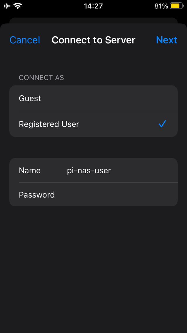
If all goes to plan the board should boot up without incident. Although there are a few things we will need to tidy up, you should now be able to SSH directly into the compute node.
$ ssh pi@192.168.50.11

pi@192.168.50.11's password:
$
If you were watching the boot messages on a monitor, or if you check in the logs, you can see that our image didn’t come up entirely cleanly. If you log back into the compute node you can make sure that doesn’t happen in future by turning off the feature where the Raspberry Pi tries to resize its filesystem on the first boot, and also by uninstalling the swap daemon.
$ sudo systemctl disable resize2fs_once.service
$ sudo systemctl disable sshswitch.service
$ sudo apt remove dphys-swapfile
Next, we should change the hostname from the default raspberrypi to rpi1 using the raspi-config command-line tool:
$ sudo raspi-configSelect System Options > Hostname to change the hostname of the compute node, and select "Yes" to reboot.
Finally, we can make things slightly easier on ourselves, so that we don’t have to use the IP address of our compute and head nodes every time, by adding our current and future compute nodes to the /etc/hosts file on both our head and compute nodes:
127.0.0.1	localhost
::1		localhost ip6-localhost ip6-loopback
ff02::1		ip6-allnodes
ff02::2		ip6-allrouters

127.0.1.1	cluster

192.168.50.1	cluster
192.168.50.254	switch

192.168.50.11	rpi1
192.168.50.12	rpi2
192.168.50.13	rpi3
192.168.50.14	rpi4
192.168.50.15	rpi5
192.168.50.16	rpi6
192.168.50.17	rpi7
Mount the scratch disk
Normally if we were mounting a network disk we’d make use autofs rather than adding it as an entry directly into the /etc/fstab file. However here, with our entire root filesystem mounted via the network, that seems like unnecessary effort.
After it reboots log back into your compute node, add a mount point:
$ sudo mkdir /scratch
$ sudo chown pi:pi scratch
Edit the /etc/fstab file there to add the scratch disk:
192.168.50.1:/mnt/usb/scratch /scratch nfs defaults 0 0Then, reboot the compute node:
$ sudo rebootSecure shell without a password
It’s going to get pretty tiresome secure-shelling between the cluster head node and the compute nodes and having to type your password each time. So let’s enable secure shell without a password by generating a public/private key pair.
On the compute node you should edit the /etc/ssh/sshd_config file to enable public key login:
PubkeyAuthentication yes
PasswordAuthentication yes
PermitEmptyPasswords no
and then restart the sshd server:
$ sudo systemctl restart sshThen going back to the head node we need to generate our public/private key pair and distribute the public key to the compute node. Use a blank passphrase when asked.
$ ssh-keygen -t rsa -b 4096 -C "pi@cluster"
Generating public/private rsa key pair.
Enter file in which to save the key (/home/pi/.ssh/id_rsa):
Enter passphrase (empty for no passphrase):
Enter same passphrase again:
Your identification has been saved in /home/pi/.ssh/id_rsa
Your public key has been saved in /home/pi/.ssh/id_rsa.pub
The key fingerprint is:
SHA256:XdaHog/sAf1QbFiZj7sS9kkFhCJU9tLN0yt8OvZ52gA pi@cluster
The key's randomart image is:
+---
[RSA 4096]----+
|     ...o  *+o   |
|      ...+o+*o . |
|       .o.=.B++ .|
|         = B.ooo |
|        S * Eoo  |
|         .o+o=   |
|         ..+=o.  |
|          ..+o +.|
|           .  +o.|
+----
[SHA256]-----+
$ ssh-copy-id -i /home/pi/.ssh/id_rsa.pub pi@rpi1
/usr/bin/ssh-copy-id: INFO: Source of key(s) to be installed: "/home/pi/.ssh/id_rsa.pub"
/usr/bin/ssh-copy-id: INFO: attempting to log in with the new key(s), to filter out any that are already installed
/usr/bin/ssh-copy-id: INFO: 1 key(s) remain to be installed -- if you are prompted now it is to install the new keys
pi@rpi1's password:

Number of key(s) added: 1

Now try logging into the machine, with:   "ssh 'pi@rpi1'"
and check to make sure that only the key(s) you wanted were added.
$
Afterwards, you should be able to login to the compute node without having to type your password.
Access to the outside world
One thing our compute node doesn’t have right now is access to the LAN. Right now the compute node can only see the head node and eventually, once we add them, the rest of the compute nodes. But we can fix that! On the head node go and edit the /etc/sysctl.conf file by uncommenting the following line:
net.ipv4.ip_forward=1After activating forwarding we’ll need to configure iptables:
$ sudo apt install iptables
$ sudo iptables -t nat -A POSTROUTING -o eth1 -j MASQUERADE
$ sudo iptables -A FORWARD -i eth1 -o eth0 -m state --state RELATED,ESTABLISHED -j ACCEPT
$ sudo iptables -A FORWARD -i eth0 -o eth1 -j ACCEPT
$ sudo sh -c "iptables-save > /etc/iptables.ipv4.nat"
and then add a line — just above the exit 0 line — in the /etc/rc.local file a line to load the tables on boot:
_IP=$(hostname -I) || true
if
[ "$_IP" ]; then
  printf "My IP address is %s\n" "$_IP"
fi

iptables-restore < /etc/iptables.ipv4.nat

exit 0
and reboot:
$ sudo rebootnote
If you still have the compute node running, you should log on to that first and shut it down, as the root filesystem for that lives on a disk attached to our head node.
Add the next compute node
Adding the rest of the compute nodes is going to be much more straightforward than adding our first node as we can now use our customised image and avoid some of the heavy lifting we did for the first compute node.
Go ahead and grab your SD card again and boot your next Raspberry Pi attached to the cluster switch.

The board should come up and be visible on the cluster subnet after it gets given an IP address by the head node’s DHCP server, and we can look at the cluster network from the head node using dhcp-lease-list.
$ dhcp-lease-list
Reading leases from /var/lib/dhcp/dhcpd.leases
MAC                IP              hostname       valid until         manufacturer
===============================================================================================
dc:a6:32:6a:15:e2  192.168.50.21   raspberrypi    2021-12-08 21:15:00 Raspberry Pi Ltd
$
We can now go ahead and SSH into the new board and again enable network booting for this board using raspi-config from the command line:
$ rm /home/pi/.ssh/known_hosts
$ ssh <username>@129.168.50.21
$ sudo raspi-config
Choose Advanced Options > Boot Order > Network Boot. You’ll then need to reboot the device for the change to the boot order to be programmed into the bootloader EEPROM.
Once the Raspberry Pi has rebooted, check the boot order using vcgencmd:
$ vcgencmd bootloader_config
BOOT_UART=0
WAKE_ON_GPIO=1
POWER_OFF_ON_HALT=0


[all]
BOOT_ORDER=0xf21
$
which should now show that the BOOT_ORDER is 0xf21 which indicates that the Raspberry Pi will try to boot from an SD card first followed by the network. Before proceeding any further, we need to take a note of both the Ethernet MAC address and serial number of the Raspberry Pi.
$ ethtool -P eth0
Permanent address: dc:a6:32:6a:15:e2
$ grep Serial /proc/cpuinfo | cut -d ' ' -f 2 | cut -c 9-16
54e91338
$
Afterwards, you can shut down the board, at least for now, and remove the SD card.
Moving back to our head node we can use our already configured image as the basis of the operating system for the next compute node.
$ sudo su
$ mkdir -p /mnt/usb/rpi2
$ cp -a /mnt/usb/rpi1/* /mnt/usb/rpi2
$ mkdir -p /mnt/usb/tftpboot/54e91338
$ echo "/mnt/usb/rpi2/boot/firmware /mnt/usb/tftpboot/54e91338 none defaults,bind 0 0" >> /etc/fstab
$ echo "/mnt/usb/rpi2 192.168.50.0/24(rw,sync,no_subtree_check,no_root_squash)" >> /etc/exports
$ exit
$
Then we need to edit the /mnt/usb/rpi2/boot/firmware/cmdline.txt, replacing rpi1 with rpi2:
console=serial0,115200 console=tty root=/dev/nfs nfsroot=192.168.50.1:/mnt/usb/rpi2,vers=3 rw ip=dhcp rootwaitand similarly for /mnt/usb/rpi2/etc/hostname:
rpi2Finally, edit the /etc/dhcp/dhcpd.conf file on the head node:
host rpi2 {
   option root-path "/mnt/usb/tftpboot/";
   hardware ethernet dc:a6:32:6a:15:e2;
   option option-43 "Raspberry Pi Boot";
   option option-66 "192.168.50.1";
   next-server 192.168.50.1;
   fixed-address 192.168.50.12;
   option host-name "rpi2";
}
and reboot our head node:
$ sudo rebootAfterwards, you should see both rpi1 and rpi2 are up and running. If you’re interested, we can get a better look at our cluster network by installing nmap on the head node:
$ sudo apt install nmap
$ nmap 192.168.50.0/24
Starting Nmap 7.80 ( https://nmap.org ) at 2021-12-09 11:40 GMT
Nmap scan report for cluster (192.168.50.1)
Host is up (0.0018s latency).
Not shown: 997 closed ports
PORT     STATE SERVICE
22/tcp   open  ssh
111/tcp  open  rpcbind
2049/tcp open  nfs

Nmap scan report for rpi1 (192.168.50.11)
Host is up (0.0017s latency).
Not shown: 999 closed ports
PORT   STATE SERVICE
22/tcp open  ssh

Nmap scan report for rpi2 (192.168.50.12)
Host is up (0.00047s latency).
Not shown: 999 closed ports
PORT   STATE SERVICE
22/tcp open  ssh

Nmap scan report for switch (192.168.50.254)
Host is up (0.014s latency).
Not shown: 999 filtered ports
PORT   STATE SERVICE
80/tcp open  http

Nmap done: 256 IP addresses (4 hosts up) scanned in 6.91 seconds
$
Add the rest of the nodes

Adding the remaining five compute nodes is now more or less a mechanical process. You’ll need to follow the process we went through for rpi2 for rpi3, rpi4, rpi5, rpi6, and rpi7. Substituting the appropriate MAC address, serial number, and hostname for each of the new compute nodes:
| Hostname | MAC Address | Serial Number |
|---|---|---|
rpi1 |
dc:a6:32:6a:16:87 |
6a5ef8b0 |
rpi2 |
dc:a6:32:6a:15:e2 |
54e91338 |
rpi3 |
dc:a6:32:6a:15:16 |
6124b5e4 |
rpi4 |
dc:a6:32:6a:15:55 |
52cddb85 |
rpi5 |
dc:a6:32:6a:16:1b |
a0f55410 |
rpi6 |
dc:a6:32:6a:15:bb |
c5fb02d3 |
rpi7 |
dc:a6:32:6a:15:4f |
f57fbb98 |
When bringing the last compute node up I also went ahead and plugged the two remaining franken-cables into the final node to power the right-most fans in my case.
Control your Raspberry Pi cluster
Now we have all our nodes up and running, we need some cluster control tools. One of my favourites is the parallel-ssh toolkit. You can install this on the head node from the command line:
$ apt install psshand, along with the excellent ParallelSSH Python library allowing you to build your own cluster automation, this will install a number of command-line tools; parallel-ssh, parallel-scp, parallel-rsync, parallel-slurp, and parallel-nuke. These tools can help you run and control jobs, and move and copy files, between the head node and the compute nodes.
To use the command line tools you’ll need to create a hosts file listing all the compute nodes, I saved mine as .pssh_hosts in my home directory:
$ cat .pssh_hosts
rpi1
rpi2
rpi3
rpi4
rpi5
rpi6
rpi7
$
After creating the file we can use the command line tools to, amongst other things, execute a command on all seven of our compute nodes.
$ parallel-ssh -i -h .pssh_hosts free -h
[1] 12:10:15 [SUCCESS] rpi4
              total        used        free      shared  buff/cache   available
Mem:          3.8Gi        56Mi       3.7Gi       8.0Mi        64Mi       3.7Gi
Swap:            0B          0B          0B
[2] 12:10:15 [SUCCESS] rpi1
              total        used        free      shared  buff/cache   available
Mem:          3.8Gi        55Mi       3.7Gi       8.0Mi        64Mi       3.7Gi
Swap:            0B          0B          0B
[3] 12:10:15 [SUCCESS] rpi2
              total        used        free      shared  buff/cache   available
Mem:          3.8Gi        55Mi       3.7Gi       8.0Mi        64Mi       3.7Gi
Swap:            0B          0B          0B
[4] 12:10:15 [SUCCESS] rpi7
              total        used        free      shared  buff/cache   available
Mem:          3.8Gi        56Mi       3.7Gi       8.0Mi        97Mi       3.6Gi
Swap:            0B          0B          0B
[5] 12:10:15 [SUCCESS] rpi3
              total        used        free      shared  buff/cache   available
Mem:          3.8Gi        55Mi       3.7Gi        16Mi       104Mi       3.6Gi
Swap:            0B          0B          0B
[6] 12:10:15 [SUCCESS] rpi5
              total        used        free      shared  buff/cache   available
Mem:          3.8Gi        55Mi       3.7Gi        16Mi        72Mi       3.6Gi
Swap:            0B          0B          0B
[7] 12:10:15 [SUCCESS] rpi6
              total        used        free      shared  buff/cache   available
Mem:          3.8Gi        55Mi       3.7Gi       8.0Mi        64Mi       3.7Gi
Swap:            0B          0B          0B
$
Although you should take note that the results will come back in a random order depending on how quickly the command was executed on each of the compute nodes.
Add a remote shutdown service
While parallel-ssh is a great tool to allow you to deploy software and do other tasks across your cluster, sometimes you just want to shut the cluster down cleanly with a single command. There are a bunch of ways you can approach this, the simplest is just to write a shell script to login to each of the compute nodes and shut them down before shutting down the head node itself. Alternatively, you could deploy something like the rshutdown service, editing the command appropriately.
Take your Raspberry Pi cluster further
Up until this point, the cluster we’ve built is pretty flexible, and now we have a firm base we can start installing software depending on exactly what we’re looking to do with our cluster. For instance, if we’re building a compute cluster for modelling, we’d probably look to install MPI and OpenMP to do parallel processing across our cluster. Alternatively, you might be looking to build out a cluster to host Kubernetes.